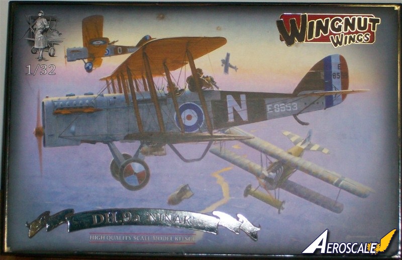
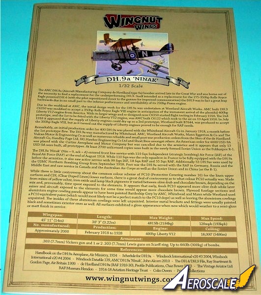
The De Havilland DH 9A, known as the 'Ninak', was developed as a medium bomber. It was produced in 1918 and saw limited service in World War One before going on to form the backbone of the Royal Air Force's post-war colonial bombing force. In marked contrast with its predecessor, the DH9, the DH9A gained an enviable reputation for reliability. Although nominally a conversion of the earlier aircraft, to take a more reliable American engine, the new DH9A was in fact a complete re-design. By the end of 1918 nearly nine-hundred had been built. Construction not only continued in Great Britain but the type went into unlicensed production in Russia for the Red Air Force. In America, where nearly 4000 had been ordered during the war, only small numbers were in fact produced before outstanding contracts were cancelled following the November 1918 Armistice. The DH 9A saw extensive service after the war, in Iraq and on the North West Frontier of India, in an aerial policing role effectively reducing the need for large numbers of ground troops. Due to the nature of these operations, it was extremely dangerous to make forced landings in hostile territory and, to assist the crews; DH 9A types carried spare wheels, bedding, emergency rations and a water supply.
The AMC DH.9a (Aircraft Manufacturing Company de Havilland design 9a) bomber arrived late in the Great War and was borne out of the necessity to find a replacement for the underperforming DH.9. Intended as a replacement for the 275-350hp Rolls Royce Eagle powered DH.4, with the pilot and gunner repositioned closer together for improved communications, the DH.9 was in fact a great leap backwards due in no small part to the inferior performance and unreliability of its 230hp Puma engine.
Due to the workload at AMC, the initial design work for the improved DH.9a was undertaken at Westland Aircraft Works. AMC built DH.9 C6350 was modified to accept a 350hp Rolls Royce Eagle VIII engine in anticipation of the immanent arrival of the plentiful 400hp Liberty V12 engine from America. With its larger wings and re-designed nose C6350 started flight testing in February 1918. The 2nd prototype, and the 1st to be fitted with a Liberty engine, was AMC built C6122 which took to the air on 19 April 1918. In July 1918 it appeared that the supply of Liberty engines could dry up so a 3rd prototype, Westland built B7644, was produced to accept the 350hp Eagle VIII, but as it turned out the supply of Liberty engines proved to be enough for RAF needs.
Remarkably, an initial production order for 400 DH.9a was placed with the Whitehead Aircraft Co in January 1918, a month before the 1st prototype flew. The DH.9a was manufactured by Whitehead, AMC, Mann Eggerton & Co and The Vulcan Motor & Engineering Co as well as numerous rebuilds and small post war production orders from the likes of the de Havilland Aircraft Co, Handley Page Ltd, HG.Hawker Engineering Co Ltd and Short Bros amongst others. An American order for 4000 USD-9A was placed with the Curtiss Aeroplane and Motor Company but was cancelled due to the armistice and it appears that only 13 USD-9A were built, all prototypes. At least 2700 unlicensed copies were built in the newly formed Soviet Union as the Polikarpov R-1.
The DH.9a Ninak (Nin = 9, ack = A) entered front line service with 110 Sqn Independent (strategic bombing) Air Force (IAF) of the Royal Air Force (RAF) at the end of August 1918. While 110 Sqn was the only squadron in France to be fully equipped with the DH.9a before the armistice, it also saw active service with 99 Sqn IAF, 18 Sqn RAF and 55 Sqn RAF. Additionally 53 DH.9as were used by United States Marine Corps (USMC) Northern Bombing Group from September 1918. Post war the DH.9a served with the RAF in Germany, Russia and the Middle East and saw service in Canada, the Australian Air Corps and the Soviet Union and China (as the R-1).
The Kit
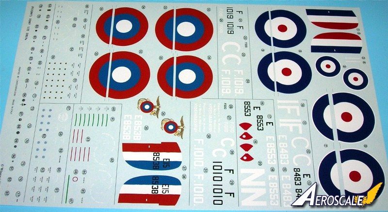
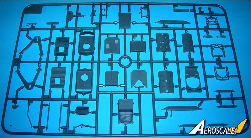
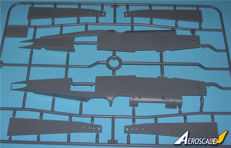
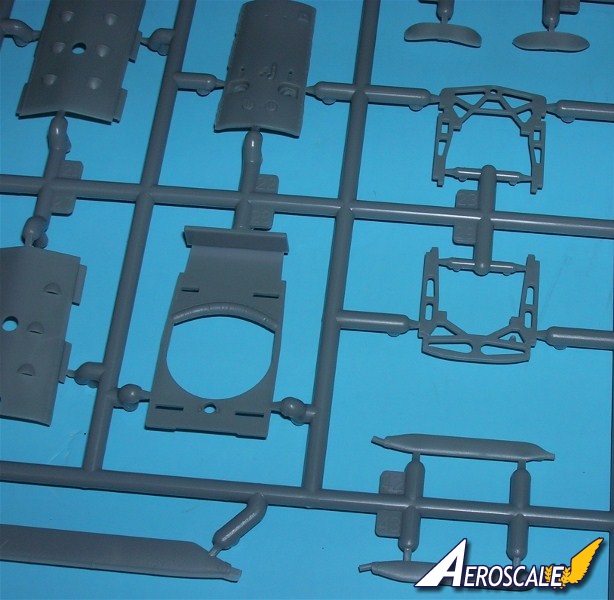
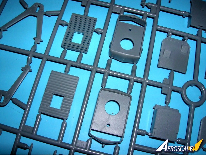
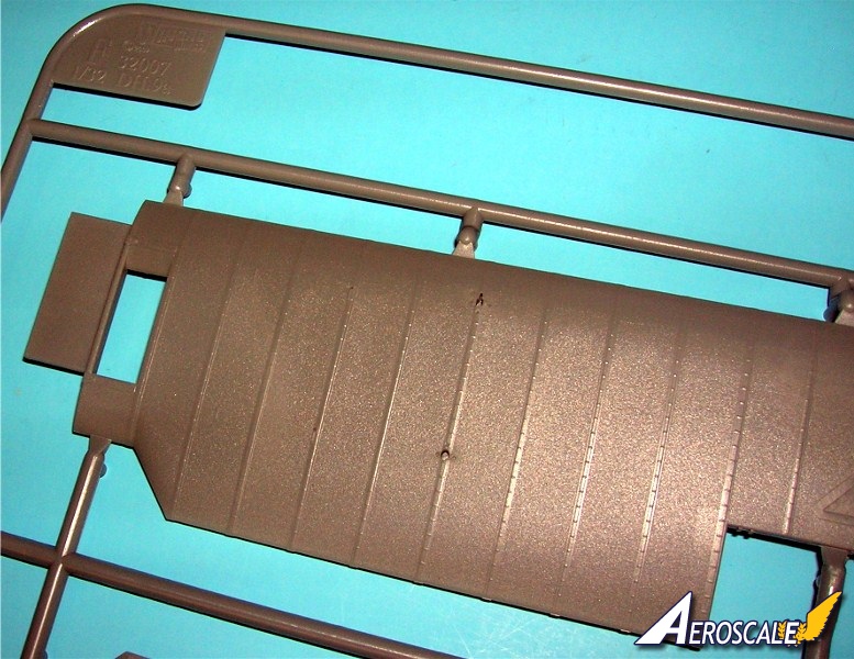
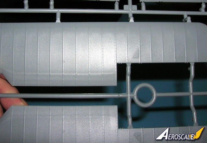
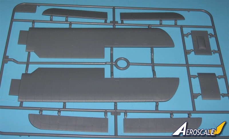
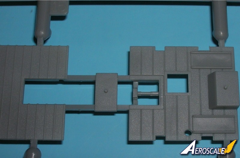
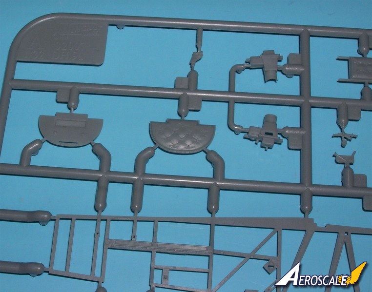
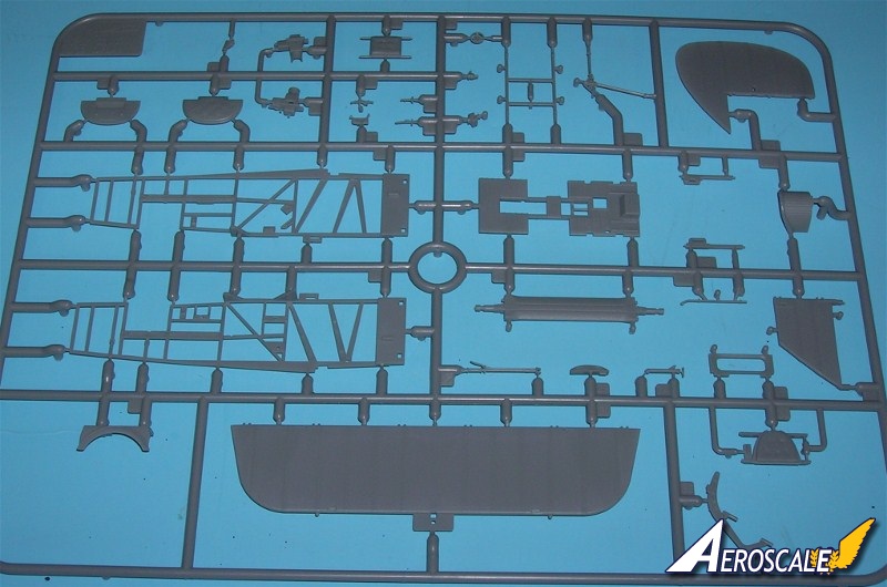
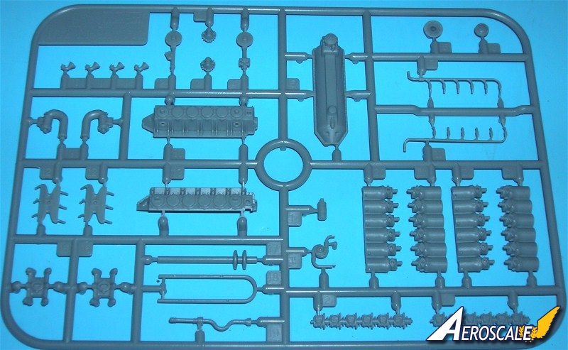
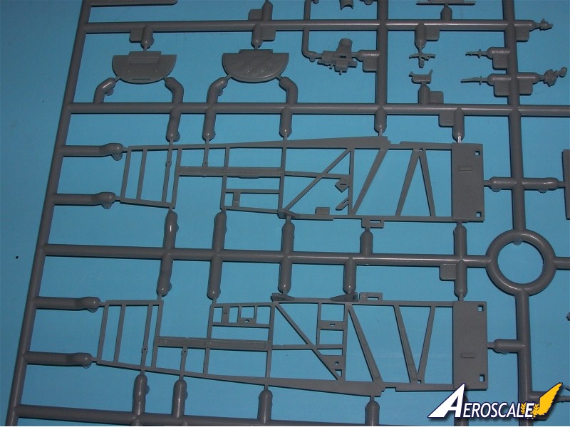
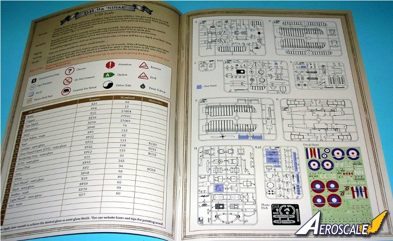
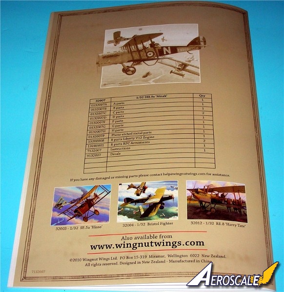
There are 295 parts, in true Wingnut Wings (WNW) fashion, crisply and cleanly molded parts in the now familiar WNW gray plastic on 11 sprues; 2 sprues each of D and R. Sprue D contains frame, exhausts wheels, flap actuators, wheels etc. and sprue R is the weapons and the scarf ring mount. The decals are spot on by Cartograf of Italy and include markings for five different aircraft to include one from 99 Squadron, a USMC aircraft, one from 155 squadron, a mostly PC-10 version, an aircraft from 205 Squadron and the Hyderabad No. 12A of 155 Squadron, which is featured in the link provided.
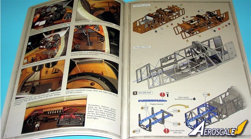
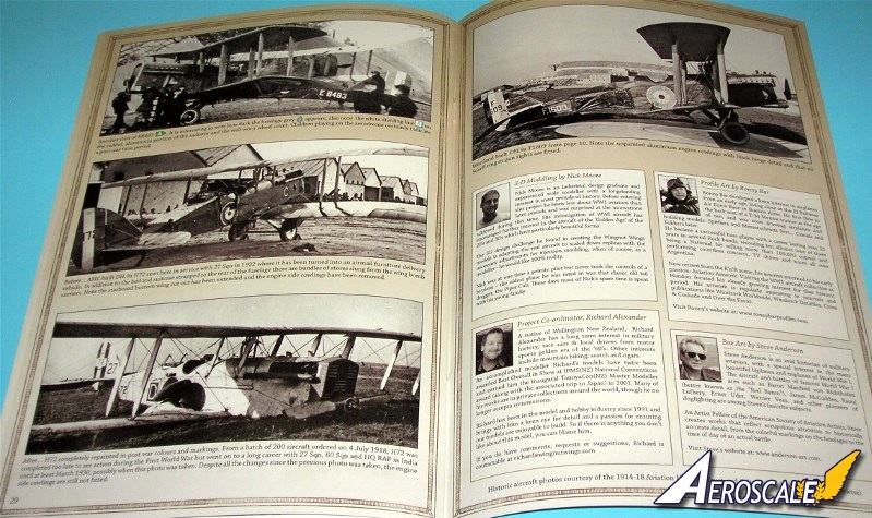
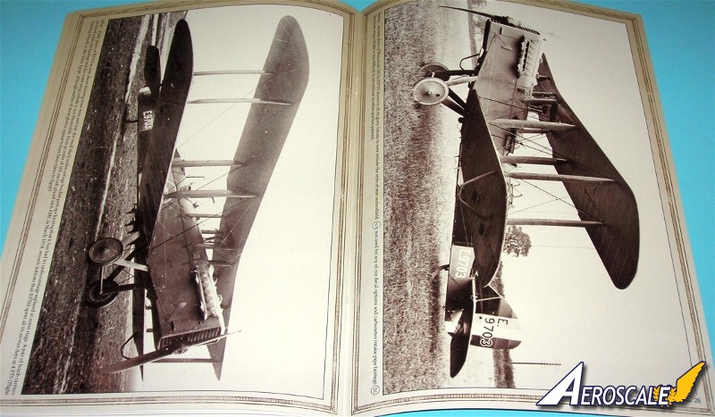
The instructions have many photos of actual DH9.as in service and restored for the modeler to reference. One of the many qualities and nice things of the WNW kitsets is the instructions which is a source document in itself and provides the modeler with many photos for reference.
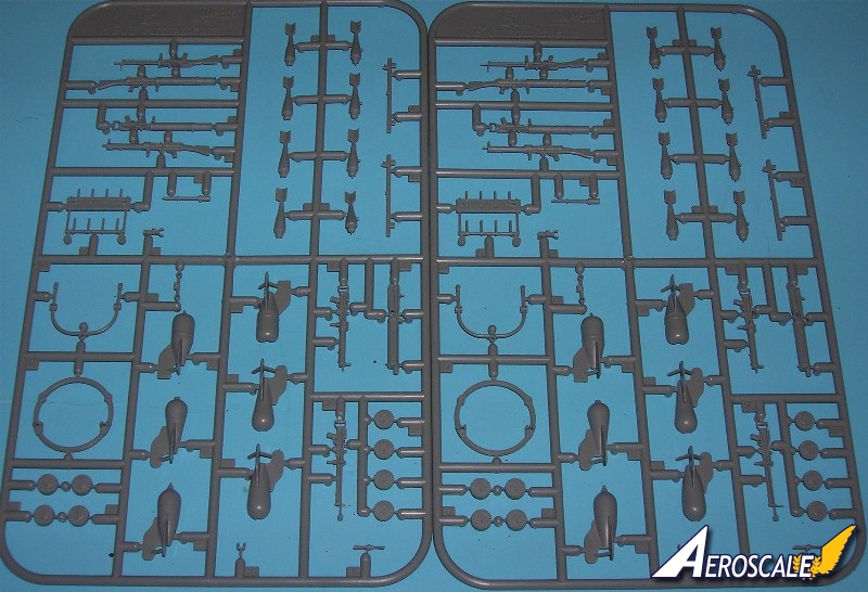
Several types of machine guns are offered which would indicate the possibility of future variants of the kit or other RFC aircraft. Pure speculation. Bombs with ordinance markings provided on the decal sheet are well detailed, as is the Liberty V-12 Engine, with a variety of exhausts and cowlings depending on the variant the modeler chooses to do
There is an erratum / corrections sheet but it is only on the website. It refers the modeler to page 3, where it shows a photo etch attachment on the pilots rudder bar. There is no PE for that part, probably due to space restraints, and then it refers the modeler to page 7 and to use part D5 carburetor stack vice part D5, on page 11 the modeler is instructed to use part H7 vice H22, which is the fuel line conduit; corrections on page 18 include the landing gear struts to use H19 and H24 vice A19 and A24, and to use the wheel retaining rings D32 vice D84.
The instructions are the typical WNW booklet with color photographs of the museum piece and many period photographs throughout the instructions to aid and assist the modeler.
Having started this model and most of the way through as of this writing plrese note! It is advised the modeler thoroughly review the instructions and make notes.
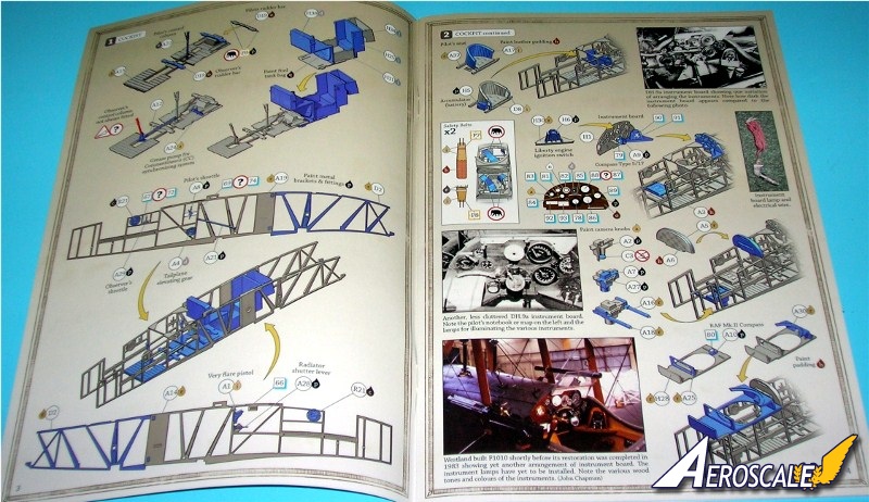
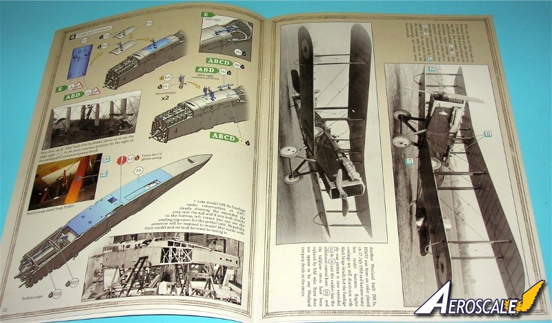
STEP 1 Cockpit. Step one involves the assembly of the cockpit. This is a critical step as fitment at this stage will affect the fit of the fuselage halves when the modeler arrives at that stage of assembly. If the modeler is going to rig the rudder bar with a turnbuckle, care must be taken to ensure the turnbuckle wont interfere with the fit of the fuselage half. The modeler is given the option of leaving or removing the observers control stick part A12. It is at this step that the fuel tank assembly and the ammo drums are attached to the port and starboard framework. There are tiny decals to be placed on part A19. Dont forget to put the grease pump part A24 during this step. If the modeler is going to rig the rudder pedals and the control levers, now is the time to do it, refer to illustrations on page 6 ensure that all rigging is within the framework as the framework sits flush against the cockpit walls and any rigging material on the outside would offset the fit.
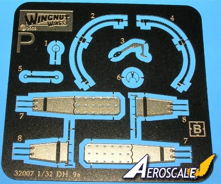
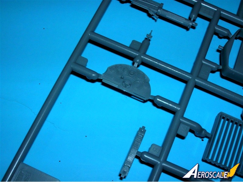
STEP 2 Cockpit Cont. Step two continues on with the cockpit, the pilot and observers seat, the instrument panel, camera, seat belts and observer decking. The WNW instructions are vague as to the placement of the seat belts. Study references and the model for attachment points. I made a SWAG and they look fine. I also annealed the PE Seat belts, not sure if I needed to as they are quite thin. Critical is the fitment of the observers seat and the camera. There are tiny mounting pins on the observers seat that fit into corresponding holes in the framework; the camera mounts have notches in the framework. Dry fitting and more dry fitting is required to ensure a proper fit. WNW has included color photographs of the restored NINAK for reference as to location and color. Very nice indeed!
STEP 3 Engine Bay. Step three involves the engine mounts and the attachment to the framework. It is critical that the modeler ensure that the engine bearers are properly justified as shown in the diagram. If not, much wailing and gnashing of teeth will ensue. Check twice before cementing. The interior rigging diagram is also on this page, but it would be prudent to pre-rig the framework before this stage.
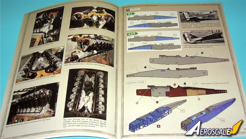
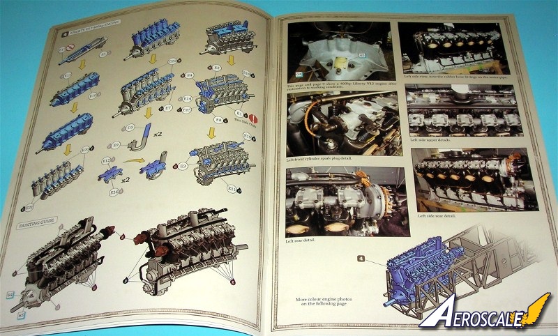
STEP 4 Liberty V12 400hp engine. Step four is the assembly of the engine. At this point the modeler can either do a perfunctory assembly or to super detail it with the engine exposed. If the modeler opts for the enclosed engine, it is hardly visible save from underneath. Assembly is pretty straightforward per the instructions however; yes there is a however, critical to the cowl fit is the fitment of the carburetor stacks and their length. The carburetor intake stack is D4 which fits onto the carburetor E9. Ensure proper fitment as the intake is angled and the slope of the angle must face outboard toward the front. The assembly attaches to part E16 which is attached to E12. This is a tricky fit and then it has to be fixed to the inside of the cylinder banks which requires some wedging, check for fitment and alignment with the cowling for the specific a/c the modeler has selected. Page 8 has detailed color photos of the engine for the modeler to reference, albeit it is a single carburetor variant. WNW has really captured the detail to include the coils on the valve springs. At the bottom of the page is a detail of the finished engine in its location within the framework.
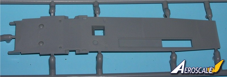
STEP 5 Fuselage. Step five requires the modeler to choose which fuselage he/she wants use as there are two variants; parts G6 & G5 represent the late variants, and G1 & G2 represent the early variant. The modeler should ensure the proper panel for the variant he/she is doing: accompanying photos highlight the differences. It is at this stage the modeler fixes parts R21, more spare magazines to the fuselage sides, and paints the interior of the fuselage. Once dry the interior framework is fixed inside the fuselage and the fuselage halves are cemented together. It is a tight fit, but all fits well without significant alignment problems.
STEP 6 Fuselage Cont. Step six includes the drilling of holes in the forward fuselage piece (H22) for the Aldis sight. Ensure variant specific holes are drilled. It is at this step that the Petrol Pumps, Aldis sight, H9 and PE part P1 (open sights) are fixed to the decking H22. Part F5, the fuselage underside is attached at this point. There are no paint instructions but the profile shows it to be fabric so paint it your favorite shade of CDL. The modeler may want to leave off part A22 until the seams are filled and sanded. Parts H37 and H31 are attached to the engine at this point as well. Again Photos accompany the assembly instructions. It is on this page (11) that the modeler is directed to the photo of the restored a/c for logo placement on the cabane struts and the upper wing under surface.
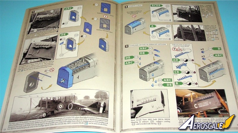
STEP 7 Radiator. Step seven involves the radiator assembly. There are two types of variant specific radiators and shutters that the modeler can choose from. Once selected the modeler can proceed to paint the radiator screens D15 (two pieces one for the front side and one for the back side; the modeler can also opt for open or closed radiator shutters. These are wood so paint accordingly. It is prudent to check the fitment of the radiator with the underside panel H16, if not attached correctly there will be alignment problems further ahead. Once proper fitment has been determined fix in place with the braces parts D34.
STEP 8 Engine Cowls. Step eight continues on with the engine cowling placement. Again at this step it is the modelers choice to fix the variant specific parts to the cowling. Care must be taken to ensure proper fit.
STEP 9 Fuselage Details and Exhaust options. Step nine is the Fuselage options and exhaust details. The modeler should ensure proper vent pieces are applied for variant specific a/c; H17 or H18, D13 or D14 are all variant specific. Parts D10 and D3 are supports for the carburetor stacks. I had to cut my stacks to ensure proper height. I thought they were way too long. This is why back in Step 4 it is critical to ensure the proper length before cementing every thing in place. Photos would indicate that the tops of the carburetor stacks (D4) should be at the same height as the supports.
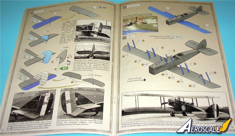
STEP 10 Tailplane. Step ten is the tail plane. This is pretty straightforward, attaching the horizontal tail plane part A31 to the fuselage, part A26, the fin to the tail plane, attaching parts D1 and D20 to the rudder part A13 and then attaching that assembly to the fin, fix control horns D20 to the elevators parts D30, finally attaching the elevators to the tail plane.
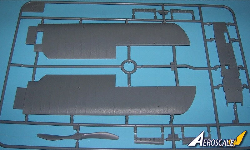
STEP 11 Lower Wings. Step 11 is the attachment of the lower wings F3 and F4 to the fuselage. The modeler will probably want to drill out the holes that are molded in the proper locations on the wings if attaching devices are to be used. In the rigging diagram on page 22 there is some internal rigging on wing part F3 that the prudent modeler will want to emplace now before painting and attaching.
STEP 12 Struts. Step 12 is the fixing of the struts to the lower wing and the cabane struts to the fuselage. WNW has taken care to Marine Proof the placement of the struts on the wings. Part H39 has the pitot tubes on it and is forward inboard on the starboard wing, part D25 is behind it; D29 is forward outboard starboard wing with D28 behind it. The holes in the wings match the stud on the struts. The modeler will want to put the variant specific strut logos on at this time prior to placement in the wing. H12 is the forward inboard port strut, with D25 behind it; D29 is the port outboard forward strut with D28 behind it. H41 and 42 are the rear cabane struts and H42 and H43 are the forward cabane struts. The modeler would really want to put these in the wrong positions. WNW has really made the placement of the cabane struts a no brainer. Again, strut logo decals should be placed before the struts are fixed to the fuselage.
STEP 13 Upper Wings. Step 13 is the fixing of the upper wings to the lower wings. The modeler must assemble the upper wing mid section parts B6 and B4. The instructions dont label the upper port wing but it is part B5 Fix upper wing B3 and B5 to the mid section and fix to the struts. If the modeler is going to use rigging attaching devices ensure holes are drilled and devices attached.
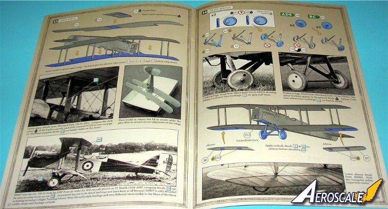
STEP 14 Undercarriage. WNW gives the modeler the choice of weighted or non weighted tires and the type of wheel cover for the variant modeled. Parts H19 and H24 are fixed to the axle wing part A20. The parts are molded to provide the proper angle. There are holes on the inboard of the struts that the modeler may want to drill further for turnbuckles. Bungee chords D7 are then attached to the axle wing with tires part D17 or D27 depending on what the modeler has chosen are then placed on the axle secured with retaining ring D32 followed by wheel covers D26 or D16; attach assembly to the fuselage. The front undershield part H16 is fixed to the lower front of the engine bay. Control horns D23 are fixed to the ailerons B8 and B7. At this point the instructions admonish the modeler to apply the lower cockade decal. Attach to the appropriate side of the lower wing.
STEP 15 Details. Attach the rear undershield part H26 to its spot on the underside of the engine compartment; attach wing skids part D31 to the outer edges of the underside of the lower wings, the camera cover, H4, can be fixed in an open or closed position. The tailskid part A33 and struts H36 can be attached at this time.
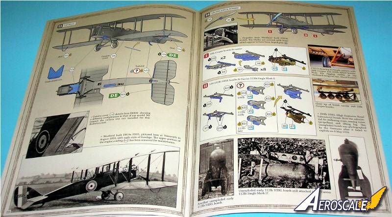
STEP 16 Propeller and Bombs. Step 16 comprises the Propeller part F6 and E6. Depending on the variant chosen, the propeller is painted gray except for a portion of the hub which is wood, be sure to check references for proper propeller. The gray represents the fabric coated part. Sub section i and ii cover the assembly of the bombs. Subsection i refers to the 20 lb Cooper bombs and carrier; fix R6 to parts D35; fix bomb parts R8 and R9, attach to carrier part R6. The modeler may want to apply the decals before attaching the bombs to the carrier. Subsection ii refers to the 100-112 lb HERL bombs and carrier 112 lb Mark II Bomb. Fix part H2 to A11, fix forward bomb latch R7 to H2 and cross members D18 to All. Cement 110 lb bomb parts R19 & F18 together apply decal 44, cement the early 112lb bombs R22 and 23 together, apply decal 45 and 112lb late style bomb R14 and 13 and decal 45 where located. WNW includes the ordinance markings on the decal sheet. A variety of armament options are available for the modeler to choose from; attach where indicated on the underside of the wings and fuselage.
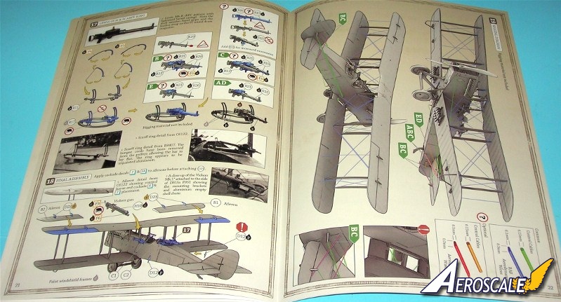
STEP 17 Lewis Gun and Scarf Ring. Get out your fine PE folding and bending skills. Carefully cut out PE parts P4 and P2 and bend accordingly. There is a recess in the scarf ring part R17 for the base of the PE parts. They go around part R11 which snaps into place in R17. Carefully cement the PE parts in the recess provided. Subassemblies show the assembly of the guns per whatever variant selected to model. Basically cementing the drum magazine R21 to the weapon R20 or R15 depending on the variant. For the twin mount fix the guns in part R12 and PE part P5 between the forward barrels. For the single mount fix the weapon in part R25. Fix in the scarf ring part R11 where indicated.
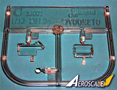
STEP 18 Final Assembly. Apply cockade decals 7 and 38 to ailerons B2 and B1 before attaching the control horns D23, fix to upper wing. Fix PE part P3 cocking handle and P6 forward part of the Vickers gun to Vickers gun part H10 and fix to fuselage where indicated. Attach forward windscreen C1 and observer windscreen C2 where indicated on the fuselage. Attach completed Scarf ring from step 17; attach control horns D12 where indicated.
Page 22. Page 22 shows the rigging diagram with insets of the various diameter rigging wire to use.
KIT DECALS.
A. E8483 IF, AMC built, 99 Sqn, October 1918.
B. E8538 E15 AMC built, C Sqn USMC, September 1918.
C. E8553 N AMC built, 155 Sqn, October 1918.
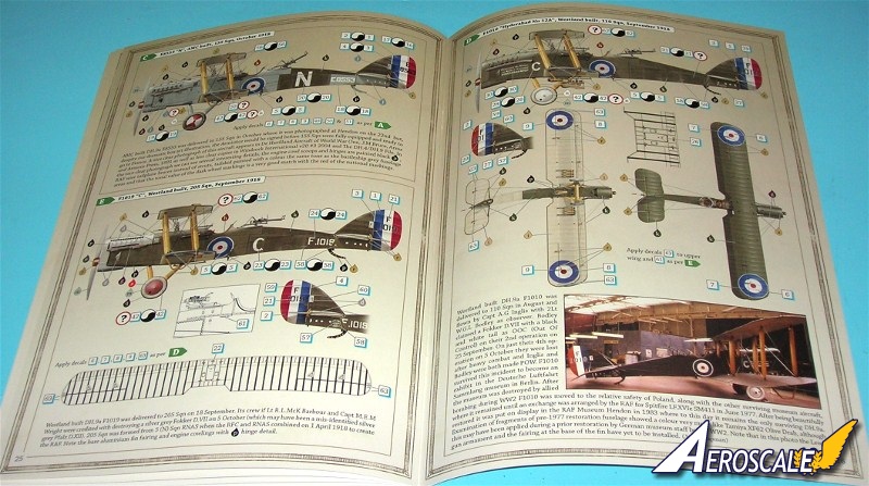
D. F1019 C Westland built, 205 Sqn, September 1918.
E. F1010 Hyderabad No.12A. Westland built.*
*This is modeled on the restoration as shown throughout the WNW instruction booklet.
REFERENCES:
Handbook on the DH.9a Aeroplane, Air Ministry, 1924 - Schedule for DH.9a .
Windsock International v20 #3 2004, Windsock International v20 #4 2004.
Windsock Datafile 139, AMC DH.9a Ninak, John Alcorn 2010.
The DH.4/DH.9 File, Ray Sturtivant & Gordon Page, Air Britain 1999.
De Havilland DH.9a (RAF 1918-30), Profile Publications, Chaz Bower 1973.
The Vintage Aviator Ltd - RAF Museum Hendon - 1914-18 Aviation Heritage Trust - Colin Owers.
When contacting manufacturers and publishers please mention you saw this review at AEROSCALE
Highs: Excellent details, a great addition to the growing 1/32nd WWI aviation line up. Fit is almost perfect. Weighted tires here is a real plusLows: Separate Instrument Bezels would have been nice; instructions not clear as to placement of seat belts, Observers seat, and camera.Verdict: A long awaited kit, deserves a place on the display shelf.
About Mark Krumrey (Mgunns) FROM: ARIZONA, UNITED STATES
Served 30 years active and reserve in the USMC. I am retired from City Government, work part time at a Harley Dealership and enjoy riding Harley Davidson Motorcycles. I started building models in about 1955 at the age of 6. My dad and I built all of the Aurora WWI subjects during those days;...


Comments