_GOTOBOTTOM
Early Aviation
Discuss World War I and the early years of aviation thru 1934.
Lozenge Camouflage 101
JackFlash
_VISITCOMMUNITY
Colorado, United States
Joined: January 25, 2004
KitMaker: 11,669 posts
AeroScale: 11,011 posts
Posted: Monday, November 13, 2006 - 06:10 AM UTC


Greetings all;
I have been up burning the midnight oil on several projects. The following treatise will do for a bit of help in the application of German WWI Lozenge camouflage. There were several types but I will be discussing their applications to model kit airframes. First a bit of history.

Halberstädter Flugzeug Werke textile mills was the company that developed and printed the Flugzeugstoff (lozenge camouflage ) with the four colour layout.

The official name for the printed fabric was Flugzeugstoff, originally developed under the name "Ballonstoff", because it was originally concieved to replace the highly visible yellow of the observation balloons.

The Vierfarbiger (four colour) Flugzeugstoff with the terrain camouflage, was the opposite to the more sophisticated Fünffarbiger (five colour) Flugzeugstoff of the NAK. The darker and cheaper dyes were used for the Fünffarbiger (5 colour) Flugzeugstoff.

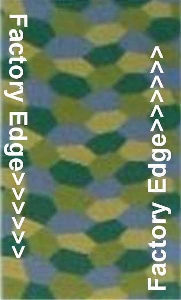
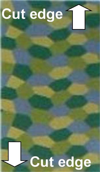
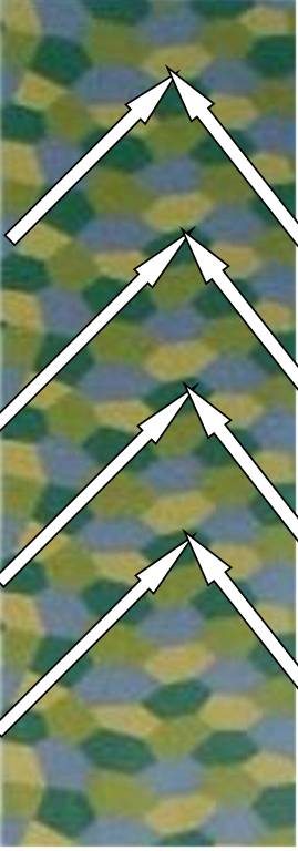
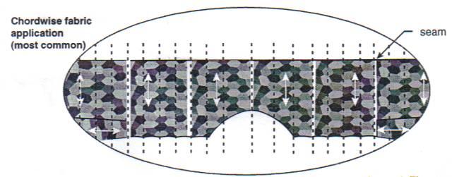
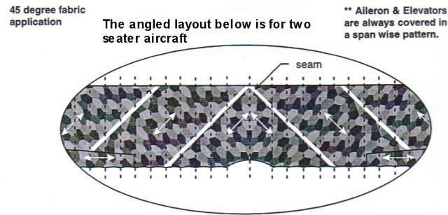
The four color fabric was 1320mm plus or minus 10mm wide and the five color fabric was 1350mm plus or minus 10mm wide. There was some movement inboard with the seams on the four color fabric. Still this amounted to six panels in most cases for a top wing.

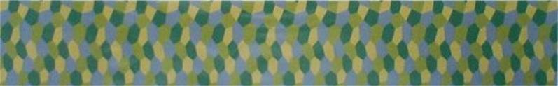
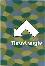
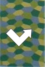
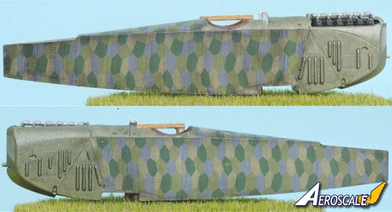
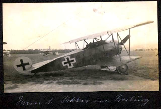
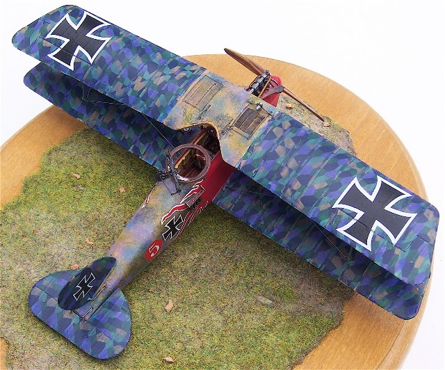
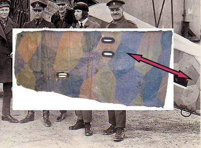
Here is a section of 4 colour lozenge fabric as applied to a Fokker D.VII fuselage. As you can see it came from the opposite side of the fuselage and further back under the tail plane. This fabric was not take from the aircraft seen as a back drop. But it is used here to denote the typical shades asociated with the orthochromatic film of the day. Note the red arrow point to a common lozenge.


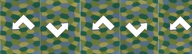
Note the definitions and descriptive labels noted here are mine in origin and are meant to be used as guidelines for modelers.
JackFlash
_VISITCOMMUNITY
Colorado, United States
Joined: January 25, 2004
KitMaker: 11,669 posts
AeroScale: 11,011 posts
Posted: Monday, November 13, 2006 - 06:41 AM UTC
Though the four colour came into use in spring 1918 , the five colour was in use as early as late summer 1917.

First we will focus on the layout of the fabric sections on the original airframes. Since almost all original wings were finished with rib tapes I should explain that I will not discuss these until later and that for now they are not shown so you will see clearly the patter layout. The fabric came from the mills on spools. These were cut in sections depending on the required layout of the fabric on the wings. The most common was chordwise.

The fore to aft orientation is called "chordwise." This runs the factory edges parallel to the lay of the ribs of most wings.

Ailerons and elevators were often covered from left edge to right edge. This is called "spanwise" where the factory edge runs parallel to the leading and trailing edges. In the field some repaired wings were covered "spanwise" as well.

The "angled" layout was usually employed on two seater aircraft with broader wing surfaces fore to aft. But later Siemens Schuckert Works used it on their production D.III (a single seater) top wing. Please note these are general observations. Stand by for some images.
JackFlash
_VISITCOMMUNITY
Colorado, United States
Joined: January 25, 2004
KitMaker: 11,669 posts
AeroScale: 11,011 posts
Posted: Monday, November 13, 2006 - 06:47 AM UTC
Next some definitions:

The long sides here are "factory" edges.


The short sides are "cut" edges

JackFlash
_VISITCOMMUNITY
Colorado, United States
Joined: January 25, 2004
KitMaker: 11,669 posts
AeroScale: 11,011 posts
Posted: Monday, November 13, 2006 - 06:54 AM UTC
Typically the lozenge fabric came off the spools at the tables for cutting and before they were cut into sections for specific wing applications it looked like this.
JackFlash
_VISITCOMMUNITY
Colorado, United States
Joined: January 25, 2004
KitMaker: 11,669 posts
AeroScale: 11,011 posts
Posted: Monday, November 13, 2006 - 06:56 AM UTC
Looking at the pattern one will notice an angled thrust line in the pattern.
JackFlash
_VISITCOMMUNITY
Colorado, United States
Joined: January 25, 2004
KitMaker: 11,669 posts
AeroScale: 11,011 posts
Posted: Monday, November 13, 2006 - 06:57 AM UTC
When the fabric section is flipped a half turn to break up the pattern you get this.
JackFlash
_VISITCOMMUNITY
Colorado, United States
Joined: January 25, 2004
KitMaker: 11,669 posts
AeroScale: 11,011 posts
Posted: Monday, November 13, 2006 - 07:01 AM UTC
When you sew these sections together at the factory edges you get.


This is the "chordwise" application of four colour lozenge fabric for the upper surfaces of a wing. Note the "cut" edges of the fabric lay against the leading and trailing edges of the wing. Like most decals you would need a smooth surface. With lozenge it wont matter whether its gloss or flat but a good coverage is needed. Spray one surface let dry and flip over and do that side.

Yes, apply the lozenge and rib tape first and then add the details. in the case of the radiator you simply allow a cut out in the lozenge. Note also the direction the lozenge goes. Alternating panel directions in usual. See the Lozenge 101 thread here.
JackFlash
_VISITCOMMUNITY
Colorado, United States
Joined: January 25, 2004
KitMaker: 11,669 posts
AeroScale: 11,011 posts
Posted: Monday, November 13, 2006 - 07:07 AM UTC
Before I proceed are there any questions?
HunterCottage
#116
_VISITCOMMUNITY
Stockholm, Sweden
Joined: December 19, 2001
KitMaker: 1,717 posts
AeroScale: 139 posts
Posted: Monday, November 13, 2006 - 12:28 PM UTC
At least for me the first pic didn't show up, but then again maybe that was made up for by the other pics that did show up.

Facinating topic! I've always been intrigued by these patterns, this article is starting out to answer all and more of the questions I have! Thanks again!

Edit: Sorry, after not getting the first pic I forced a refresh of my browser and it showed up. So it seems everything is in working order now.
JackFlash
_VISITCOMMUNITY
Colorado, United States
Joined: January 25, 2004
KitMaker: 11,669 posts
AeroScale: 11,011 posts
Posted: Monday, November 13, 2006 - 09:30 PM UTC
Thank you HunterCottage for your kind words.

Just to refresh your memory and with the information presented here, now you may be able to understand a little better the directional layout oif the fuselage applied lozenge. (As seen in the thread texturing lozenge decals) See here.


Note the key lozenge pointed out in the first posting with the red arrow. Find it and then you will notice the thrust angle. Note also that the key lozenge is in almost the exact position as the first image.

On the other side the key lozenge dissappears near the bottom longeron.

For the fuselage; The application of lozenge panels was done differently between the three licence builders of the Fokker D.VII. That is The factory edges were not applied to the same longerons. Because of their factory assembly lines layout patterns of lozenge were not the same between Fokker Schwerin, Albatros Johannistahl and East Albatros Works Schneidemuhl.

Note Longerons are the long corner edges of the fuselage two upper, two lower.

For good references on the subject;
Fokker D.VII Covering Practices by Dan-San Abbott, WWI Aero #102, Pp.22-33. 1984.
Fokker D.VII Detail Marking and Finish of Fokker-built D.VII Aircraft by Dan San Abbott, WWI Aero #107, 1985.
Kitboy
_VISITCOMMUNITY
Gelderland, Netherlands
Joined: July 20, 2006
KitMaker: 258 posts
AeroScale: 256 posts
Posted: Tuesday, November 14, 2006 - 02:29 AM UTC
Maybe it's my lack of mathematics, my not perfect English or my eyesight, but I do not see a "thrust angle" on the pictures of the DVII fuselage. For me the whole stoyr is a bit hard to understand, but that really has to do with the fact I cannot completely follow the meaning of some words. But,... my English friend is comming back to Arnhem next week, and I'll ask him. He knows a lot more about applying lozenge then I do anyway, so he probably can give me a lesson along with this explanation.

I want to do a Fokker DVII 1/48 OAW built in the nearby future, and I am certainly not going to use Eduard's decals which are included this time.

Greetings, Nico

P.s. Stephen still a very nice explanation

P.p.s. Brisfit is nearly finished
JackFlash
_VISITCOMMUNITY
Colorado, United States
Joined: January 25, 2004
KitMaker: 11,669 posts
AeroScale: 11,011 posts
Posted: Tuesday, November 14, 2006 - 02:51 AM UTC
No worries Nico;
If you can't quite understand it then I need to explain it better. Note if you will the "thrust angle" is a reference to the line up of the lozenges. First just look at the tan ones., Note the white angle I have placed on the field and then note where the dark green lozenges are. They all come from one factory side at a staggered angle like a wedge. Then they cut back to the other factory side. like an off angled and inverted "V" Also remember that I noted in the texturing thread that Eduard has the positions for the light green and purple lozenges reversed. As an educated observer you will be able to note this in the future.

grandadjohn
_VISITCOMMUNITY
Arizona, United States
Joined: October 24, 2006
KitMaker: 33 posts
AeroScale: 27 posts
Posted: Tuesday, November 14, 2006 - 04:52 AM UTC
At last, an article that I can understand on how to apply the patterns
BadBoyFLSTC
_VISITCOMMUNITY
California, United States
Joined: November 20, 2005
KitMaker: 96 posts
AeroScale: 53 posts
Posted: Tuesday, November 14, 2006 - 06:38 AM UTC
I don't understand what the key lozenge is

Nils
JackFlash
_VISITCOMMUNITY
Colorado, United States
Joined: January 25, 2004
KitMaker: 11,669 posts
AeroScale: 11,011 posts
Posted: Tuesday, November 14, 2006 - 09:15 AM UTC

Note the dark green key lozenge pointed out from the first posting with the red arrow. Find it on the model and then you will notice the thrust angle. Note also that the key lozenge on the model is in almost the exact position as this colour image. Also remember that I noted in the texturing thread that Eduard has the positions for the light green and purple lozenges reversed.


On this side the key lozenge dissappears near the bottom longeron.
JackFlash
_VISITCOMMUNITY
Colorado, United States
Joined: January 25, 2004
KitMaker: 11,669 posts
AeroScale: 11,011 posts
Posted: Wednesday, November 15, 2006 - 10:22 PM UTC
Greetings all;
To continue with the chordwise layout here is the Eagle Strike instuctional drawing concerning the chordwise layout. But note the pattern is not alternated as is done on my wing example posted previosly above.

The thrust angle of the lozenges points toward the leading edge of the wing consistantly. Also this instuctional drawing depicts a union seam of the fabric lays directly on the midway / center division of the upper wing.

In some cases the wing pattern was begining on the wing's left wing tip and the same union seam is not on the center line division. Both cases of these applications did exist. Also ailerons were covered spanwise.


JackFlash
_VISITCOMMUNITY
Colorado, United States
Joined: January 25, 2004
KitMaker: 11,669 posts
AeroScale: 11,011 posts
Posted: Wednesday, November 15, 2006 - 10:36 PM UTC
More on the lozenge camouflage from a noted research fiend;

As described by Lt. Col. Roy Houchin USAF in a recent interview he comments on the 4 & 5 colur lozenge applications that were found on Fokker D.VI airframes in the spring / summer 1918.

‘In classic fashion...it depends. The mainplanes were completed and covered at a period in time where the change from five-color to four-colour was occurring.(Note the parent company Fokker at Schwerin /Gorries had used five-colour on the wings of the early production Fokker D.VII types.) Subsequently, both patterns appear on airframes (of the D.VI) in no particular order or serial number. However, four-color seems to be the dominant lozenge fabric at least for the fuselages. Rather than placing the fabric seam on the centerline of the wing, Fokker's fabric shop worked from the port wing tip in the case of the D.VI. The resulting seam was just outboard of the first rib to starboard of the center (as viewed by the pilot.) The fabric strips rib and border tapes were made of the same (lozenge) material. They were applied everywhere except the ribs of the control surfaces. The leading edge plywood caps were reinforced with, chordwise strips of plain fabric over the ribs and are visible as outlines under the doped lozenge fabric in some pictures as they are wider than the rib tapes. On elevators and ailerons, the pattern ran spanwise with the cover for one surface cut from one edge; its opposite number was cut from the middle of the roll and inverted. The horizontal Tailplane fabric pattern was run spanwise as well. It's best to look long and hard at the specific photograph to glean any particulars.’

HunterCottage
#116
_VISITCOMMUNITY
Stockholm, Sweden
Joined: December 19, 2001
KitMaker: 1,717 posts
AeroScale: 139 posts
Posted: Thursday, November 16, 2006 - 01:31 AM UTC
The idea of a key lozenge is also new to me, but if I am understanding things the thrust angle in you two model halves you have showed, will be toward the bow of the plane. Is this correct?
JackFlash
_VISITCOMMUNITY
Colorado, United States
Joined: January 25, 2004
KitMaker: 11,669 posts
AeroScale: 11,011 posts
Posted: Thursday, November 16, 2006 - 02:54 AM UTC

Quoted Text

The idea of a key lozenge is also new to me, but if I am understanding things the thrust angle in you two model halves you have showed, will be toward the bow of the plane. Is this correct?


Greetings HunterCottage;

The key lozenge is just a term I use here to get the reader to focus on one specific area of the lozenge pattern. You will probably never see the term outside this thread.

Yes you are right in saying the thrust angle points toward the nose of the fuselage as the pattern has been layed down.
HunterCottage
#116
_VISITCOMMUNITY
Stockholm, Sweden
Joined: December 19, 2001
KitMaker: 1,717 posts
AeroScale: 139 posts
Posted: Thursday, November 16, 2006 - 03:00 AM UTC

Quoted Text

Yes you are right in saying the thrust angle points toward the nose of the fuselage as the pattern has been layed down.


Whoohoo! I can actually learn!!!

Actually this is very interesting, which is why Aeroscale (Armorama/Kitmaker) rocks! Still upset with Jim that made several sites so I have to flip back and forth... :-)
JackFlash
_VISITCOMMUNITY
Colorado, United States
Joined: January 25, 2004
KitMaker: 11,669 posts
AeroScale: 11,011 posts
Posted: Friday, November 17, 2006 - 04:07 AM UTC
Greetings all;

Since there appears to be a general understanding of what I am describing, I will proceed with the 45 degree angled pattern layout. Since the 4 colour pattern did not exist before the Fokker applications of spring 1918 it is safe to say that most of the angled applications were in 5 colour. Remember also that this is a printed pattern not painted.


Yet the lozenges we often see on the big Zeppelin Stakken R types (4 engine high altitude bomber) were in fact painted. (One known exception was R.30) Zepplein must have learned valuable lesson in that they did not use printed fabric again on the big airframes.

Now on to the the 45 degree angled layout. The following is typical.


The image is from Aeroscale member Dwayne Williams and shows the Techmod 5 colour pattern on a Blue Max 1/48 scale Halberstadt CL.II. (Note the texturing he employed here.

See his build featured on the Homepage or under "Features".
Click Here.
JackFlash
_VISITCOMMUNITY
Colorado, United States
Joined: January 25, 2004
KitMaker: 11,669 posts
AeroScale: 11,011 posts
Posted: Friday, November 17, 2006 - 04:13 AM UTC
Since Pegasus images have disappeared from the www it gives me great pleasure to present Dwayne's build again.
JackFlash
_VISITCOMMUNITY
Colorado, United States
Joined: January 25, 2004
KitMaker: 11,669 posts
AeroScale: 11,011 posts
Posted: Friday, November 17, 2006 - 04:34 AM UTC
Note the application of the Eagle Strike 5 colour lozenge here on my build of the early Eduard SSW D.III 8356/17 . The top wing is at 45 degree in one direction across the whole upper surfaces. The lozenge on the lower wing and elevator are spanwise, more on that later.
Lucky13
_VISITCOMMUNITY
Scotland, United Kingdom
Joined: June 01, 2006
KitMaker: 1,707 posts
AeroScale: 1,119 posts
Posted: Friday, November 17, 2006 - 04:53 AM UTC
This is absolutely awesome Stephen!! The best that I've seen a anywhere about the Lozenge camouflage...here's to you matey.

JackFlash
_VISITCOMMUNITY
Colorado, United States
Joined: January 25, 2004
KitMaker: 11,669 posts
AeroScale: 11,011 posts
Posted: Friday, November 17, 2006 - 02:42 PM UTC
Thanks for the kind words Jan;

Now to continue on the topic of Angled layouts for lozenge. As has been mentioned the predominate type will be five colour but there are exceptions to the rule (after about May 1918.) Below you have the the Eagle Strike instructionals for the "Angled" layout. The center area where these opposing angles come together is usually done on wing panels rather than one piece solid wings.

In otherwords the center line area is
1. where two wing panels butt up against each other as with an Albatros C.V or a Rumpler C.IV

2. or butt up against a centersection like on the Halberstadt CL. II, CL. IV or the Hannover CL.II , CL.III, or CL. IIIa.


These opposing 45 degree angle layouts were supposed to have every other panel flipped so the thrust angle would be different as well. But as with any assembly line operation this was not always the case...there were exceptions.

The lower wing panels of course did butt up against the fuselage. According to photo evidence I have seen there was not any angle of the fabric that was applied to the fuselage. Though as has been discussed previously the factory edge lined up with either the top or bottom longerons.
 _GOTOTOP