The Fokker D.VII became the Germanys largest production fighter in 1918. Usually matched with the Mercedes D.IIIaü 180hp engine. It was the variant with the BMW IIIa 185hp that pilots prized. With few idiosyncracies it was not temper-mental and a novice with a little nerve could do well.
Contemporary construction used welded metal tubing for the fuselage and wooden wing structures was typical. The secret appeared to be in the Cantilever boxed wing spars and the simple design that eliminated the need for multiple rigging wires. For several reasons the Fokker D.VII is a must have item in the serious collector/modelers stable. The lack of rigging is a big plus. The various lozenge patterns, unit and pilot markings that are available in decal form is another. Also books on the subject are also at an all time high. In 2001 at a European Toy Show far, far away, a cottage industry manufacturer displayed his 1/48 scale rendition of the Fokker D.VII (OAW) mid production variant batch that includes serial 4100/18 to 4599/18 with the louvre profiles presented.
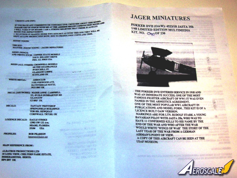
The Kit
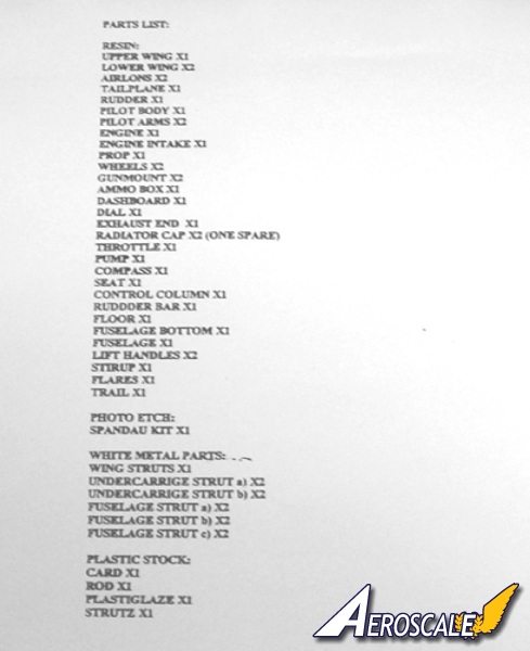
This is Jagers first attempt at a single seat fighter. Typically for this company there are only 230 of these resin kits were manufactured. I purchased units #40 & 41. There are 4 plastic pcs, 37 resin pcs & 12 metal pcs. Fuselage is one piece. Instructions are 7 pages (1/2 Euro sized) w/ 2 plan views. Decals are for Ltn. R. Stark cmdr of Jasta 35b. While the price is a little more than twice that of the high volume contemporaries, Jager had beaten the big boys to the draw with this beautiful kit. Jager gave credits to well known contributing manufacturers. The old Copper State models provides resin wings & photo-etch, Cromwell provides the rest of the resin, Aeroclub provided beautiful white metal struts and Eagle Strike 4 colour Lozenge upper & lower sheets. The national and personal markings were done by a local talent. All in all a good piece. For those of us lucky enough to have the Jager Fokker D.VII, you can be reasonably assured of a good build.
The Build
Step 1. The Mercedes inline cylinders are a specific representation of the Mercedes D.IIIaü 180hp inline six. Check the references provided for some keynote differences. On the original aircraft the cylinder jackets themselves were the color of blued metal. The BMW is needed to do some Fok. D.VII profiles. I like the Roden BMW IIIa. Truthfully, most people wont know the difference. The original BMW IIIa sat higher in the compartment, so about 1.5" more of the cylinders could be seen. The air induction pipes were unified where the Mercedes was divided. The immediate visual difference in the early Mercedes D.III 160hp / D.IIIa 170hp and its progeny the D.IIIaü 180hp is the location of the rocker assembly covers/boxes compared to the rocker springs. On the early D.III and D.IIIa the rocker springs are centered on the sides of the Rocker Box covers. On the D.IIIaü the springs are located on the forward leading edge of the same covers. So it appears that the boxes themselves were moved back in that design. The springs themselves were always located on the centerline of the cylinder jacket profiles. They were also that way on the BMW IIIa 185 hp. The rest is below the cowling and not readily visible. Several good manufacturers note the difference and have two distinct castings for the Mercedes D.III 160hp and the D.IIIaü 180 hp. The Mercedes D.III 160hp was outclassed by 1917. The Mercedes D.IIIaü 180hp was the standard engine in both the Albatros D.Va starting in late 1917 and the Fokker D.VII through 1918.
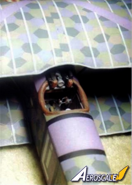
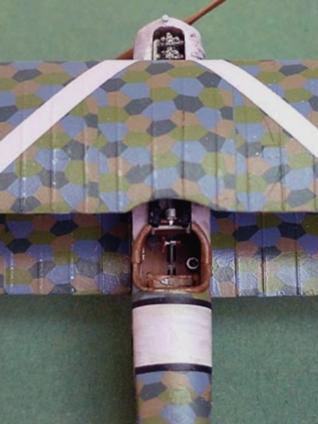
Step 2. The seat comes together on a pedestal in the cockpit floor. The harness belts that are molded to the seat and I added the Supports with painted brass rod. The seat backplate was covered in fabric that was held by attaching it to eyelets in the seats outer rim. As parachutes came into use the seat was made deeper to accommodate the chute-pack as a cushion. As mentioned the lap and shoulder harness straps are molded into the seat, so after I removed them I added spares from my parts box. I removed the molded in cockpit structure. Note that the factory printed lozenge pattern fabric used on the Fokker D.VII faintly showed through to the interior of the cockpit sides in reverse. Eagle Strike decals are done on a clear carrier so they can be reversed, but need to be attached with sol & set. then thinly over sprayed in off white. The earlier streaked type of Fokker camouflage did not penetrate the fabric in the same way the printed lozenge type did. Simply off-white will suffice here. The cockpit rear bulkhead / screen you should pre-drill holes for rudder control cables to be added later. I normally use the same lozenge covering on the seat and rear cockpit bulkhead that is on the fuselage. In the case of streaked camouflage I go with plain off white or dirty white. For the rest I would choose 4 or 5 colour lozenge camouflage decal.
Step 3. Next I add cut and painted brass rod sections to the cockpit interior. On the cockpit flooring set the rudder control assembly and control column to the desired position to compliment the attitude you have chosen for the separate ailerons, elevators and rudder. The control column is very fragile and was broken in both my kits. I scratch-built an aileron control V for cables and attach the V at the front end of control and cockpit Floor assembly.
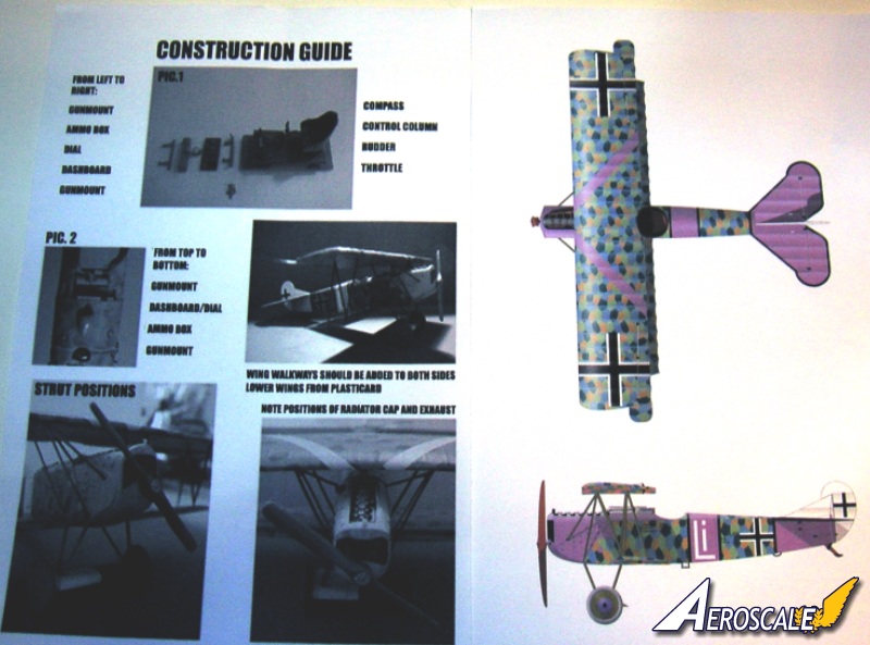
Step 4. I will usually paint Fokker Company instrument panels black and all others give a varnished wood look. I replaced the two fuel gauges (main & reserve) on the instrument panel with faces from Eduard Albatros D.V or Copper State Models aftermarket items. Add a hand crank type handle to the dash mounted starter magneto, also flip levers to fuel and air controls. I also add a tachometer dial to the MG rear brace. Next add the forward and rear machine gun braces with the ammo box and instrument panel between them. The ammo box should be similar in profile to the DML Fokker Dr.I item. The lower corners should be notched (for the pilots legs to reach the rudder bar) as well.
Step 5. Now you should add the compass to the cockpit floor and a fuel pressure hand pump to the pilots right and a throttle/ fuel-air mixture quadrant to the pilots left on the cockpit sidewall structure. Check your references. I find that Toms Modelworks or Part of Poland brass interior sets are great. They often provide just the right pieces to complete the job. Before uniting the fuselage and the cockpit floor, add rigging material to the base of the rudder control column and rudder bar. Then when dry slip the ends of the wires first into the pre-drilled holes in cockpit rear bulkhead as you fit the cockpit floor in place.. Check the sit of the kit engine making sure that it lines up well with centerline of the fuselage. There may be a need to trim some resin on the lower ends of the cylinders. Open up the tail skid aperture in the rear portion of the fuselage near the stern post. Note the instructions say that will have to add a 2 mm plastic shim as filler to the mating surface of the fuselage for the horizontal tail unit. I found that taking 1mm from each side of the balances on the horizontal tail surface leading notch allowed me to fit the piece. The resultant shelf was where the tubing for the elevators rested. Check your references.
Step 6. The old Copper State provided - fretted gun jackets are nickel coated and heating these is recommended before annealing them over your DML jacket former. I added the empty belt chutes with bent metal-rod. The ammunition belt feed chutes should connect the ammo box to the intakes on the right side of the MG breaches. The completed Spandau Maxim machine guns should be painted in semi-gloss black. All German issue Spandau and Parabellum machine guns came from the factory with the outer surfaces covered in baked on black enamel. Some highlighting over all surfaces in a gun metal colour maybe appropriate. For gun metal I like the Testors Metalizer gun metal buffing paint. The molded cowling side panels determine the parentage of your D.VII as an OAW mid production variant. I used a flex file to thin down their perimeter edges slightly.
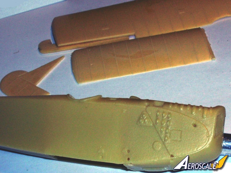
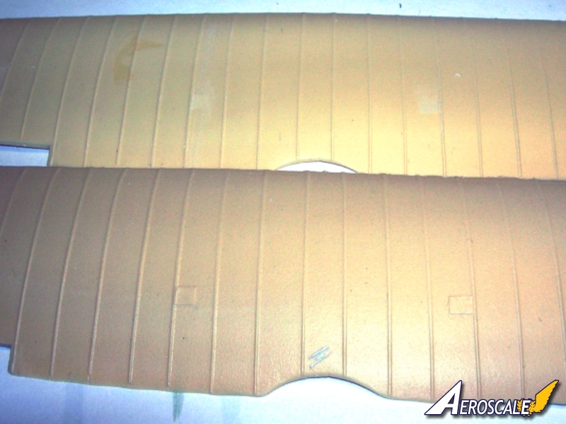
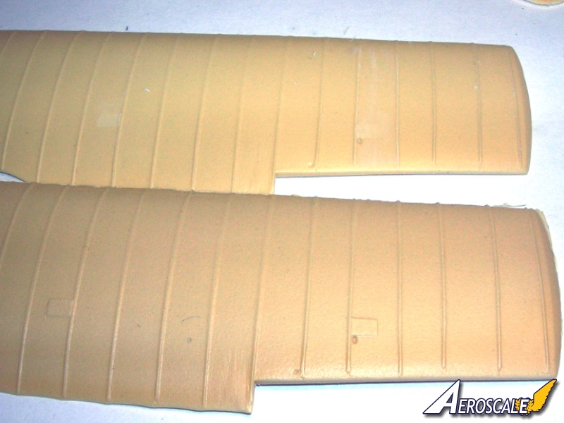
Step 7. The wings dont seem to have many of the usual molding or resin associated problems. I had a minor curve in mine that was easily rectified with immersion in warm water. Normally Ill take two pieces of picture frame glass (two narrow pieces) and clamp the wing between them with rubber bands then drop it into warm water for about 20-30 seconds. Next, you could drill out the strut sockets in the wings to add depth. Now you will note the patches on the top wing surface. These need to be only on the undersurface of the top wing. Shave them all off and replace 2 of them with .005 thou plastic sheet. They are reinforcement patches for the aileron control entry ports from the fuselage. Check your references and compare the wing gap using dividers or even a inexpensive school compass. Here check the fit of your ailerons. They come as separate pieces and I had to cut into the top wing slightly with a small file. These are then fitted with brass rod sections inserted into pre-drilled holes in both the top wing aileron notches and the aileron leading edge. To bring the assembly together I use childrens Lego blocks to form a jig to keep everything level and square. Then usually I will scratch-build the cabane struts from the appropriate diameter brass rod. Add the half-moon Strut attachment points in plastic to the underside of the top wing as well. Then top these off with Grandt Line hex nut-heads. In one kit I had (#41) two right side ailerons in the other I had (#40) the normal left & right side ailerons.
Step 8. Add the landing gear Vee legs to the airfoil sockets. Add the stabilizer struts with brass rod. Check the attitude of the Step and Grab Handles. These are a determining factor in the factory of origin. If you intend to use metal wire for rigging, use dividers or a compass to get the right lengths. For resin I tend to stick with brass wire. Steel or florists wire can be moisture contaminated and since many hobby resins use formaldehyde as a basis the white metal wire can start to rust. Brass wire doesnt seem to have this problem and can be tinted with model rail road hobby black and attached with great results. Ceramic wire is also a good choice. I didnt add the kit resin tail skid it is too flimsy. I scratch built one from brass rod. I squared the faces with a grinding tool and bent to shape. I made it long enough to sink into a pre-drilled hole and added a brace of smaller diameter brass wire.
Step 9. The aileron control horns were added from Toms Modelworks set. The kit propeller is a little under nourished for my tastes. I will replace the kit item with either one that I take from my spares box and paint to match the laminations or I will scratchbuild one by laminating layers of light and dark woods and sanding to shape. This is a rather easy process and gets easier with each attempt. There are ready made items from Micro Group. See the review here at Aeroscale.
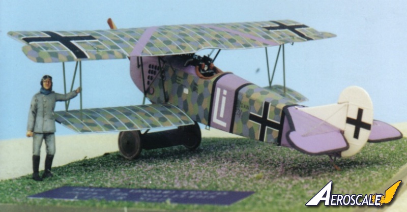
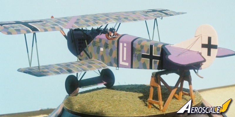
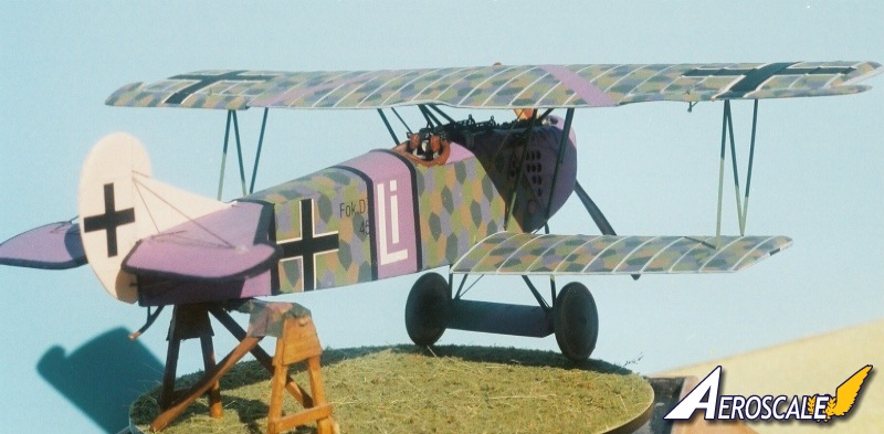
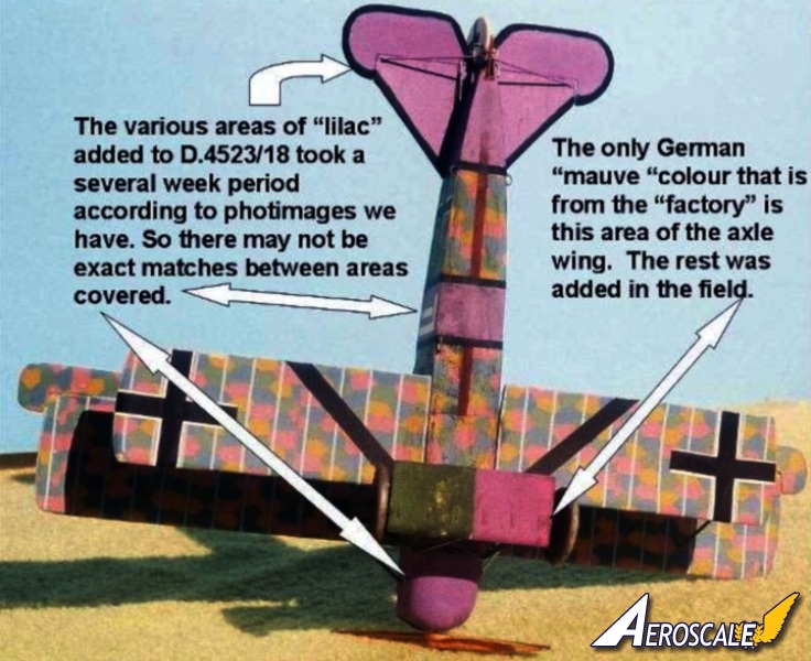
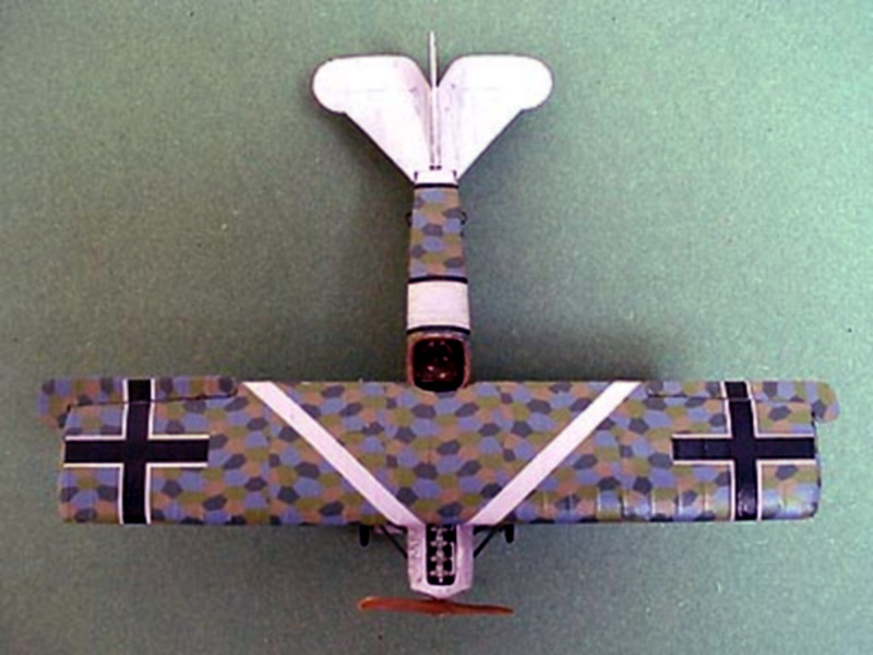
Fokker D.VII (OAW) 4523/18 of Jasta 35b after September 15, 1918 and flown by the commander Ltn. R. Stark. This is the Jager resin kit with only slight modifications to the cockpit contents. The Jager pilot has been modified by replacing is kit 'head' with a Jaguar item.
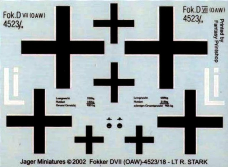
Kit Decals:
The Lozenge The kit decals are from the old Eagle Strike line and unfortunately are OOP. I highly recommend Microsculpts 4 & 5 Colour Lozenge camouflage kit items. They provide several sources with several trial prints and took notes before they settled on the final issues. The Pantone colouring is very close to the original fabric dyes. These dyes were taken from the colored inner surfaces at the electron-micro level by highly regarded authorities.
The national and personal markings are designed and printed within the UK. My sets are right on register. Jager provides a colour plan view and a colour photo of the finished model in profile. Note the light blue rib tapes, the black wing chevron/ bands and the mauve/lilac chevron/band are not included by design. This gives the builder the chance to thoroughly use one type of their paint to match the whole scheme. If Jager had given us the lilac band its a good bet the paint we used would not match his decals. The light blue rib tapes were not included as their easy to replicate and would only increase the overall cost. While showing some forethought consider that Starks D.4523/17 scheme was NOT completed in a short period of time. Having the Lilac painted locations not completely match, may be more accurate.
Let me encourage you here to use the same colour rib tapes on top and bottom of the wings. The examples we have in the Lafayette Foundation show that the rib tape was used in one piece on the whole wing rib profile. In general, from the factory Fokker used Lozenge strips, OAW used light blue and lozenge and Albatros used Salmon pink and lozenge. Check which profile you intend on doing. Note also that there are cases where wing components were mixed at the unit level as replacements.
References:
1. Combat Colours #14 The Fokker D.VII by P. Cooksley, Airfix Magazine. Date unknown.
2. Details & Colours Windsock Intl. Vol.3 #3 Summer 1987.
3. Fliegertruppen #2 by A.Ferko, Privately Published, Salem Ohio, 1987. photocopies may be obtained by contacting the University of Texas at Dallas through the special aviation collection.
4. Flight Report Cross & Cockade Great Britain, Vol. 2 # 4.
5. Fokker D. VII Aces of WWI, pt. I by Franks & Van Wyngarden. Osprey pub. 2003.
6. Fokker D. VII Aces of WWI, pt. II by Franks & Van Wyngarden. Osprey pub. 2004.
7. Fokker D.VII by Egon Kreuger, Profile Pub. Ltd. 1962.
8. Fokker D.VII by P. Grosz, Albatros Pub. Ltd, Datafile #9. 1989, 1993, & 1994.
9. Fokker D.VII Anthology 1 by R.Rimell, Albatros Pub. Ltd. 1997.
10. Fokker D.VII Anthology 2 by R.Rimell, Albatros Pub. Ltd. 2000.
11. Fokker D.VII Anthology 3 by R.Rimell, Albatros Pub. Ltd. 2002.
12. Fokker D.VII Kit Survey by R.Rimell, Albatros Ltd. Windsock Vol 13, #4 1997.
13. Fokker D.VII Covering Practices by Dan-San Abbott, WWI Aero #102, Pp.22-33. 1984.
14. Fokker D.VII Detail Marking and Finish of Fokker-built D.VII Aircraft by Dan San Abbott, WWI Aero #107, 1985.
15. Fokker Fighters of WWI by A. Imrie, Osprey, Vintage Warbirds #6 Pp.41-64 1986.
16. Fokkers Last Deadly Scourge by M. OLeary, Air Combat, Pp. 18-26. 1975.
17. Forgotten Fokker by P Cooksley, Cross & Cockade GB Vol.4, #2,Pp.84-86. 1973.
18. That Fokkers an Albatros! By Wally Tripp, WWI Aero, #102 , Pp.14-21. 1984.
19. Udets Fokker D.VII Fighters by Dan-San Abbott, Windsock Vol.4, Spring 1989.
20. German Army Air Service in WWI by R.Rimell, Osprey, Vintage Warbirds #2, Photos 42-44, 1985
21. Germanys Last Knight of the Air by C. Degelow, William Kimber Pub. London, 1979.
22. Wings of War by R. Stark, Arms & Armour Press. 1973.
When contacting manufacturers, sellers and publishers please mention you saw this review at AEROSCALE
Highs: Good quality resin and white metal parts. Very decent decals from multiple sources.Lows: Cost. Top wing being too thin in profile, wrong placement of the aileron reinforcement patches. Kit engins cylinder bank under scale. Verdict: Even with other excellent kits that came later This kit was a real contender. With work it makes an good display.
About Stephen T. Lawson (JackFlash) FROM: COLORADO, UNITED STATES
I was building Off topic jet age kits at the age of 7. I remember building my first WWI kit way back in 1964-5 at the age of 8-9. Hundreds of 1/72 scale Revell and Airfix kits later my eyes started to change and I wanted to do more detail. With the advent of DML / Dragon and Eduard I sold off my ...


Comments