The Scimitar stemmed from a number of designs from Supermarine for a naval jet aircraft, initially to a requirement for an undercarriage-less fighter aircraft to land on flexible "sprung" rubber decks, which would allow for a lighter and simpler structure. Supermarine's design to meet this requirement was the Type 505, featuring a thin, straight wing and a V-tail (or 'butterfly tail') to keep the tail surfaces away from the jet exhausts, and to be powered by two Rolls Royce Avon turbojets, mounted side-by-side in the fuselage. In 1948, the Admiralty had second thoughts about the undercarriage-less fighter, and Supermarine reworked their design by including a nose wheel, becoming the Type 508. The Vickers-Supermarine Type 508 was the first Scimitar sharing the basic layout of the Type 505. An order for three Type 508s was placed in November 1947.
The first Type 508 made its maiden flight from Boscombe down on 31 August 1951, with the aircraft carrying out carrier trials aboard HMS Eagle in May 1952. The second aircraft had significant differences, carrying a cannon armament, and different enough in detail to be re designated the Type 529, flying for the first time on 29 August 1952. One unusual modification was the larger tail cone that was to accommodate a proposed tail-warning radar. The maximum speed of the straight-winged Type 508 and 529 was relatively modest, with the Type 529 reaching 607 mph (977 km/h), and it had already been decided when the Type 508 first flew to redesign the third prototype with swept wings to improve performance. The resulting Type 525 also featured conventional swept tail surfaces as well as blown flaps to reduce the aircraft's landing speed, and first flew on 27 April 1954. It later crashed but the basic design had already proved sound enough to proceed with an outwardly fairly similar looking aircraft, the Type 544. A total of 100 were ordered although the Royal Navy had changed the specification to a low level strike aircraft with nuclear capability rather than a dedicated fighter.
The first of the Type 544s serving as prototypes for the later production series flew on 19 January 1956. The aircraft evolved more with the third Type 544 incorporating different aerodynamic changes and a stronger airframe strengthened for the new low level role. Various aerodynamic "fixes" to try and counter pitch-up effects at high speed and altitude included flared-out wingtips and wing fences. The tail plane was also changed from dihedral to anhedral. The combined modifications led to the final Type 544 being considered the "production standard". The first production Scimitar flew on 11 January 1957.
At the time of introduction the Royal Navy only had a couple of large carriers, most were still quite small and the Scimitar was a comparatively large and powerful aircraft. Landing accidents were common, and the introduction of the type was marred by an fatal accident which took the life of Cdr John Russell, commanding officer of 803 naval Air squadron, the first squadron to operate the Scimitar. After making a perfect landing on the newly-recommissioned HMS Victorious, and in full view of the press, one of the arrestor wires broke, and Russell's Scimitar fell into the sea. With no means of ejecting through the jammed canopy, and despite the best efforts of the plane guard to perform a rescue, Russell's Scimitar sank to the bottom and Cdr Russell drowned. Overall the Scimitar suffered from a high loss rate; 39 were lost in a number of accidents, amounting to 51% of the Scimitar's total production run. The aircraft was perceived by many as too innovative mechanically. It pioneered fuel flow proportioning and integral main plane tanks along with "blown" flying surfaces to reduce landing speeds. At one time, it held the notorious record of 1,000 maintenance hours per flying hour. Although the Scimitar could be equipped as a fighter the interceptor role was covered by the de Havilland Sea Vixen. In the attack role it was replaced by the Blackburn Buccaneer. The Scimitar was retained initially as a tanker to compensate for the early Buccaneer's low endurance. A Buccaneer would take off with minimum fuel then top up from a Scimitar.
Source: Wikipedia
The Kit.
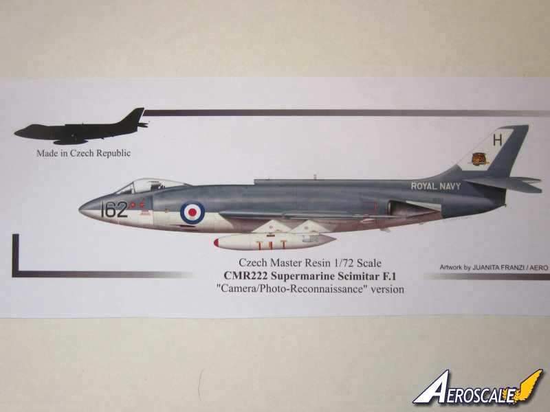
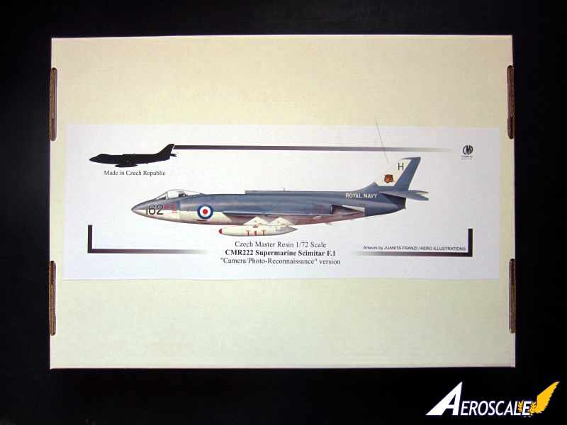
This is an entirely new moulding of the Supermarine Scimitar contained in a very sturdy box with reinforced ends. There is an excellent illustration on the box cover of XD323 by illustrator Juanita Franzi, definitely worth keeping. All resin parts are placed in multi cell plastic bags. Canopies, masks, decals and photo etched [PE] parts are sealed separately. For added safety there are lots of foam peanuts stopping things from rattling and moving around.
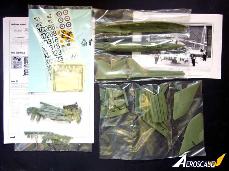
Contents
-85 x Resin parts approx.
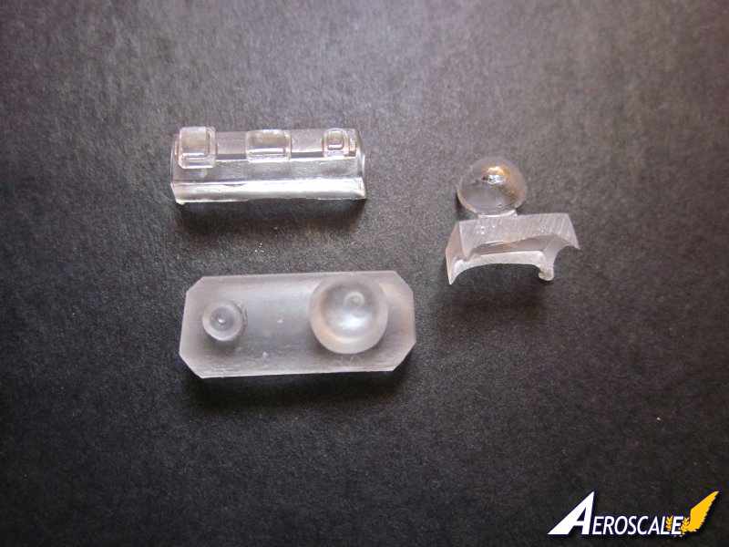
-6 x clear resin parts
-2 x vac formed canopies.
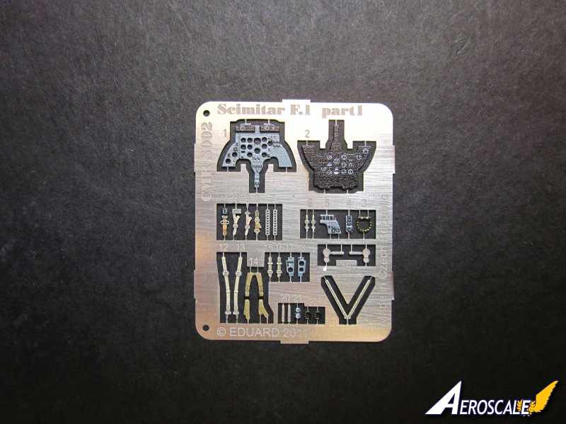
-1 x pre coloured photo etched fret.
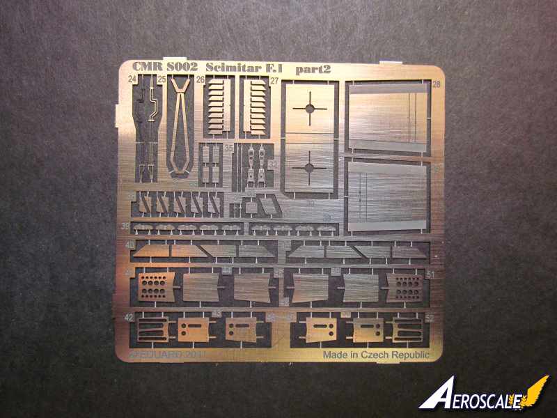
-1 x larger non coloured photo etched set.
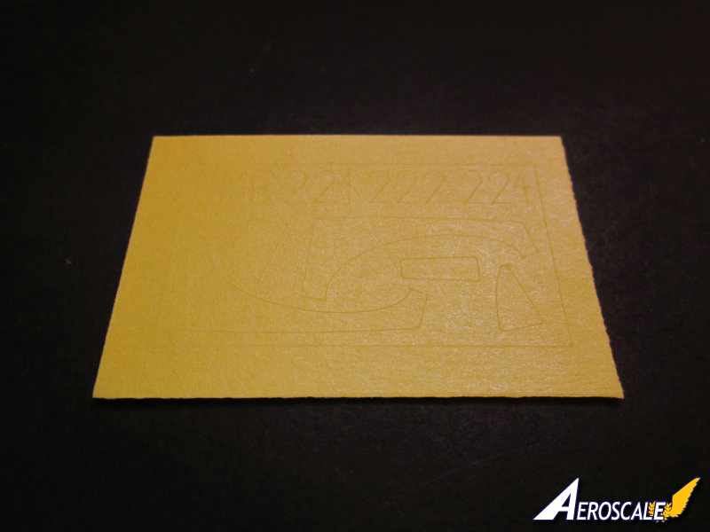
-1 x canopy masks.
-2 x decal sheets.
-6 x A4 pages: guidance and construction instructions.
-8 x A4 pages: camouflage schemes and decal application guide
-2 x A4 pages: payload assembly and marking guide.
-3 x A4 pages: payload configuration guides.
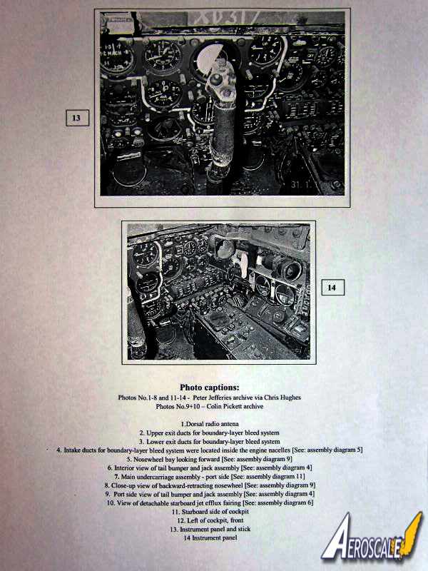
-7 x A4 black and white photographic references and captions.
First impressions are that this is a pretty big single seat aircraft, particularly for one intended to land on small British Carriers.
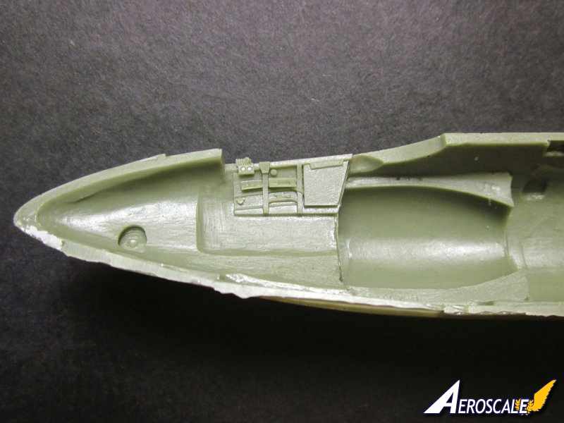
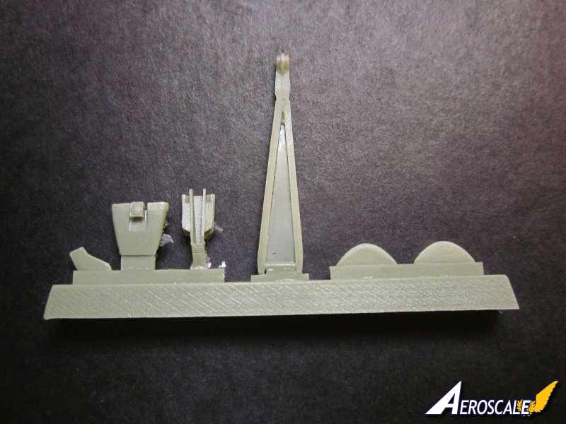
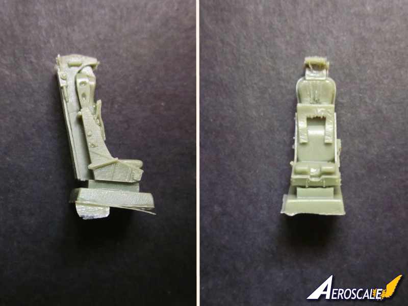
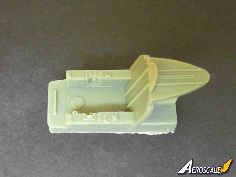
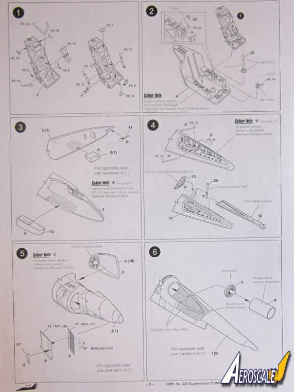
Cockpit:The superbly detailed one piece MB Mk.4C ejection seat needs the casting block removing. There are a number of pre coloured photo etched parts to add, including harnesses, straps and seat activation cords. The cockpit tub is one piece, with some excellent low relief detail representing instruments and switches on the side consoles . Some care will be needed not to reduce the casting block too much as this forms the cockpit floor. The control stick is resin and the throttle levers and rudder pedals are photo etched parts. The instrument panel in front of the pilot is built up from five pre coloured photo etched parts. The completed instrument panel is attached to the separate instrument hood. The inside of the fuselage halves where the cockpit is located again has some fine cast detail, which has additional photo etched parts to add interest.
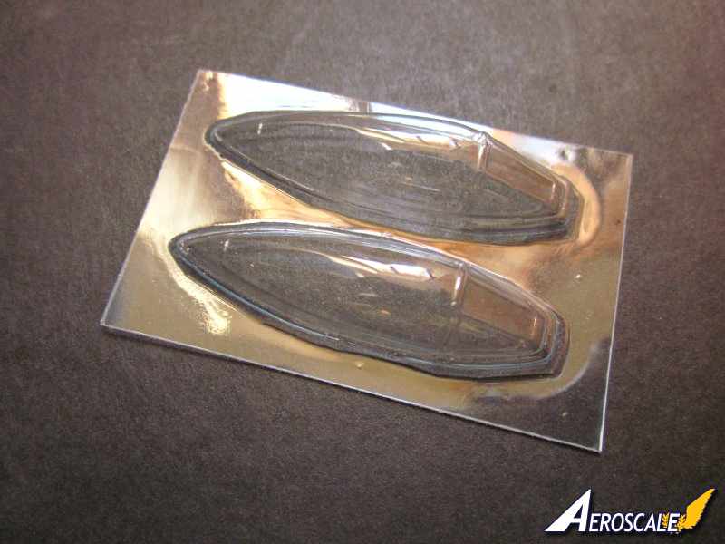
Canopy: the good folk at CMR have provided two vac formed canopies formed on the one sheet. The canopies are thin, very clear with some positive looking raised frames.
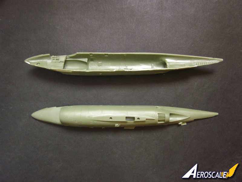
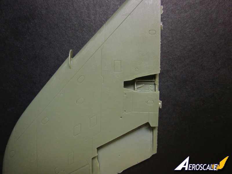
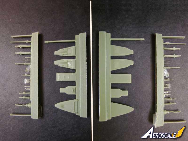
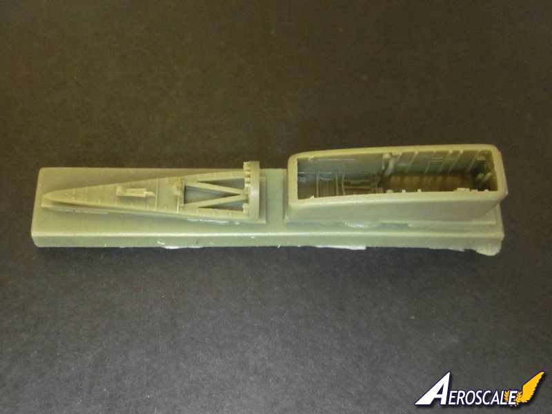
Fuselage: is split vertically. The recessed panel lines are clean and very consistent. I particularly like the gun troughs, the detail within the airbrake and the arrestor hook bays and the shape of the fuselage just aft of the jet pipes. Also worth mentioning are the seven small air intakes cast on the surface of the fuselage. There is a little resin flash over the engine air intakes, engine exhausts, and the front undercarriage bay, which should be simple enough to remove. The edges of the two halves of the lower fuselage will need some attention to ensure a good fit. The roughness is where the casting block has been removed. Lining the two fuselage halves together shows that all the panel lines meet each other perfectly and there is no warpage at all.
A little surgery is require to the fuselage, including:
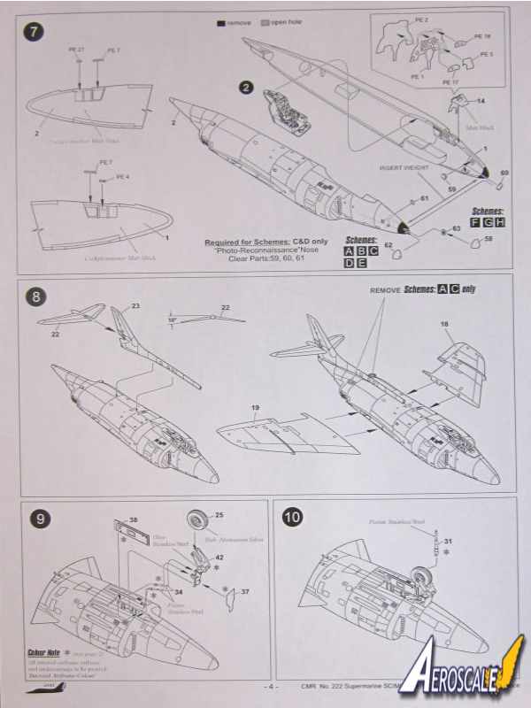
-Removing the very tip of the nose and replacing it with the clear resin nose tip representing the 'Harley light' or the opaque resin nose tip of the gun camera. The camera window is represented by a clear spot on the opaque resin.
-The three camera ports in the nose need to be drilled out and shaped. To make things easier for the modeler CMR have reduced the thickness of the resin inside the fuselage around the camera ports and also marked the margins of the camera ports on the outer surface. The holes are filled with resin clear parts.
-The two small air inlets on the rear upper fuselage need removing to depict two of the aircraft accurately.
-Depending which version you are building one or two of the cannon troughs need filling.
-If the refueling probe is not being fitted, the hole where it attaches to the fuselage needs filling.
I cannot stress enough that you study the instructions thoroughly and you also need to decide which version you are building before you commence. CMR have gone to a lot of trouble producing a model that is as accurate as possible it would be a shame to be halfway through the build and discover that you had missed something because you built the kit on instincts. The work described above should be within most modelers abilities.
Before the fuselage halves can be joined the cockpit, arrestor hook bay, engine air inlets and jet pipes, front undercarriage bay, and camera windows in the nose need to be fitted.
The main gear bay in the fuselage needs fitting as well. Although the doors are closed and only open during the cycling of the undercarriage, the fuselage wheel bays prevent seeing into the fuselage. There is a little flash that needs removing in the gap where the wheel bay is located in the wing root.
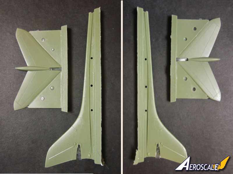
The tail is cast separately and is in one piece. The truncated spine is cast onto the tail and features a air inlet at the front. The inlet is nicely done with enough depth in the inlet to give the impression that it is a duct. Rudder is cast into the tail and the detail similar to the rest of the kit is well done, particularly the low relief grilled vents. The trailing edges are superbly thin.
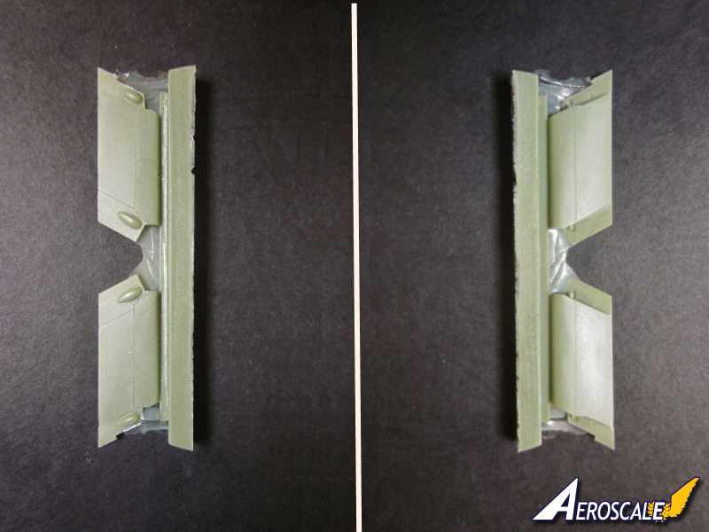
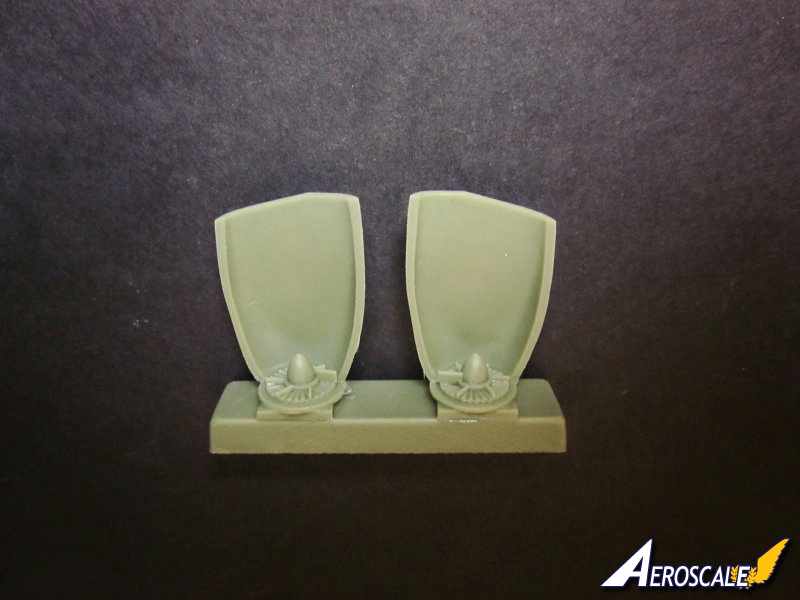
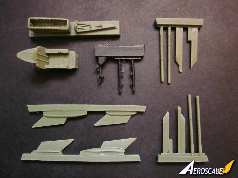
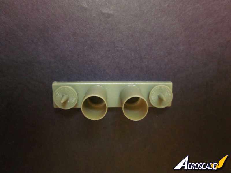
One half of the air ducts for the engines are cast with the fuselage. The other half is cast separately and includes the primary compressor blades of the engines. The casting of the detail of the blades looks very effective. The separate inner half of the ducts has a liner made up from three photo etched part, placed on top of each other to imitate the complex nature of this area. Some folding of the photo etched parts is required, the excellent instructions and photo image of the port air intake will help you through this part of the build. The photo etched parts also have the advantage of covering over the join between the separate halves of the air ducts and the fuselage.
The jet pipes are one piece meaning seamless pipes, always a real bonus. The low pressure turbines at the rear of the engines are cast separately.
To the rear of the Scimitar, the bay where the tail hook is located has nicely cast detail on the walls of the bay. The separate roof of the bay includes a bulkhead that prevents seeing through into the fuselage. Again the roof and bulkhead are nicely detailed. There is a separate tail skid, which can be modeled in the lowered position. The tail hook has a thin film of resin between the arm that will need to be carefully removed. The hook can be displayed in the lowered position as well.
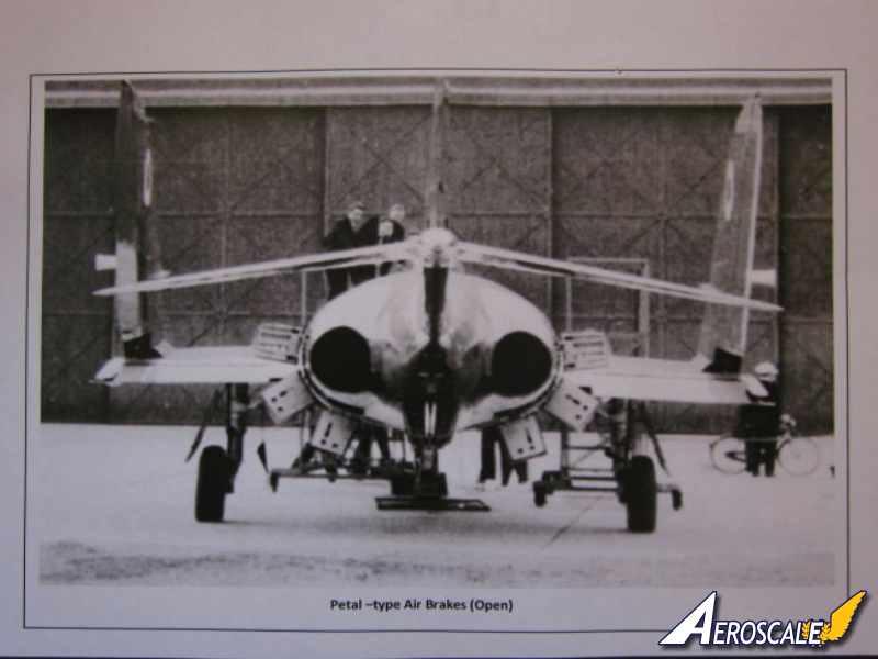
The air brakes [dive brakes] on the Scimitar are particularly interesting. There are six of them that form a skirt just forward of the jet pipes when open. The air brake bays are beautifully detailed. Each airbrake is made up from two photo etched parts. Modeling the air brakes open will certainly add interest and a talking point amongst your fellow modelers. CMR provide an excellent image of the rear of a Scimitar with its air brakes fully open.
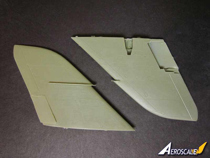
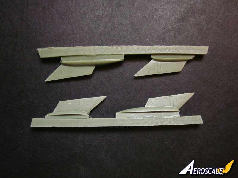
Wings: the two one piece wings are beautifully cast with excellent recessed detail. The wing fence is commendably thin, so some care is required when handling the wing to avoid damaging the fence. The flaps are separate, there is a thin film of resin covering the area where the flaps locate. Obviously as the flaps are separate they can be displayed in the lowered position. There are resin actuators for the flaps if you do decide to lower the flaps. The shaped part of the inner wing where the flaps fit should ensure a positive fit, no matter what position you place the flaps. I really like the thinness of the wings skin where it can be seen around the undercarriage bay. The detail in the main gear bay is superb. The trailing edges on the wings and the separate flaps are superb, nice and sharp. The very short pegs on the wing that fit into the holes in the fuselage fits snuggly. The remnants of the casting block on the wing/fuselage joint needs cleaning up. Once done the fit of the wing to the fuselage is very good indeed.
There is no facility to show the wings folded with this release. But CMR do supply a separate wing fold set [CMR-DS06] for the Scimitar.
The stabilisers are one piece with beautifully thin trailing edges and have the 10° anhedral set. There is a cut out just forward of the bullet fairing enabling the unit to slide into the slot in the tail.
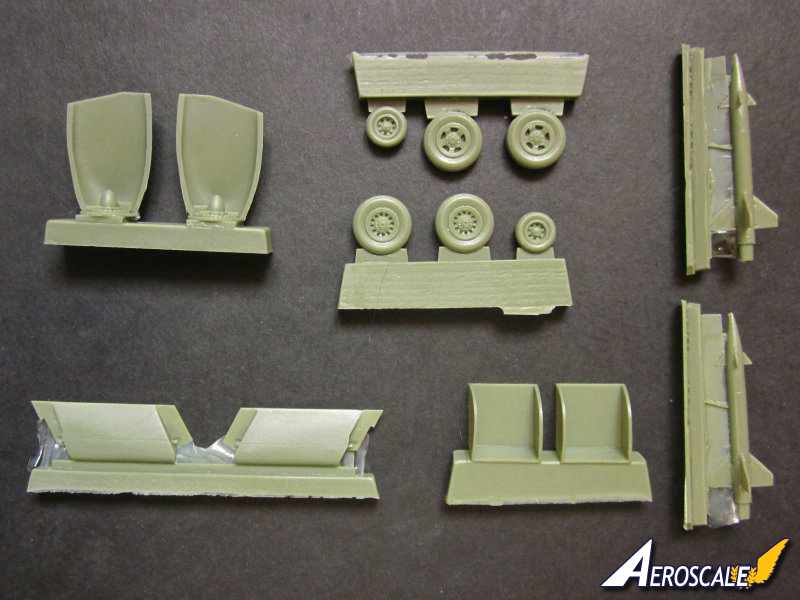
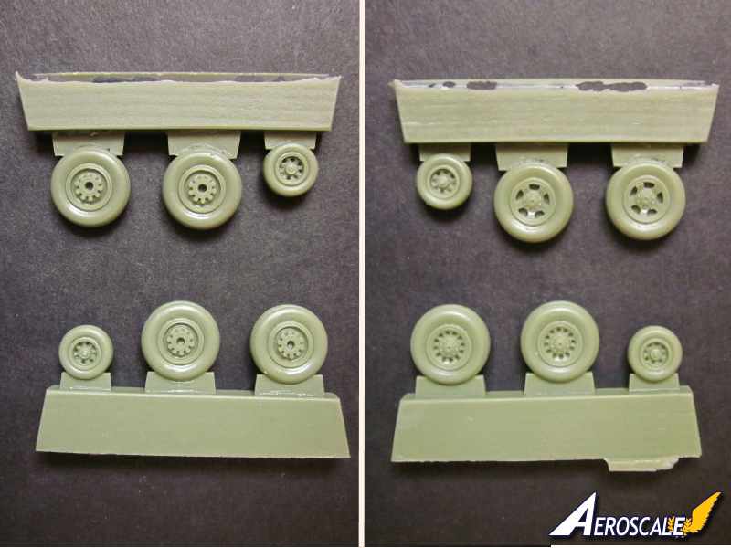
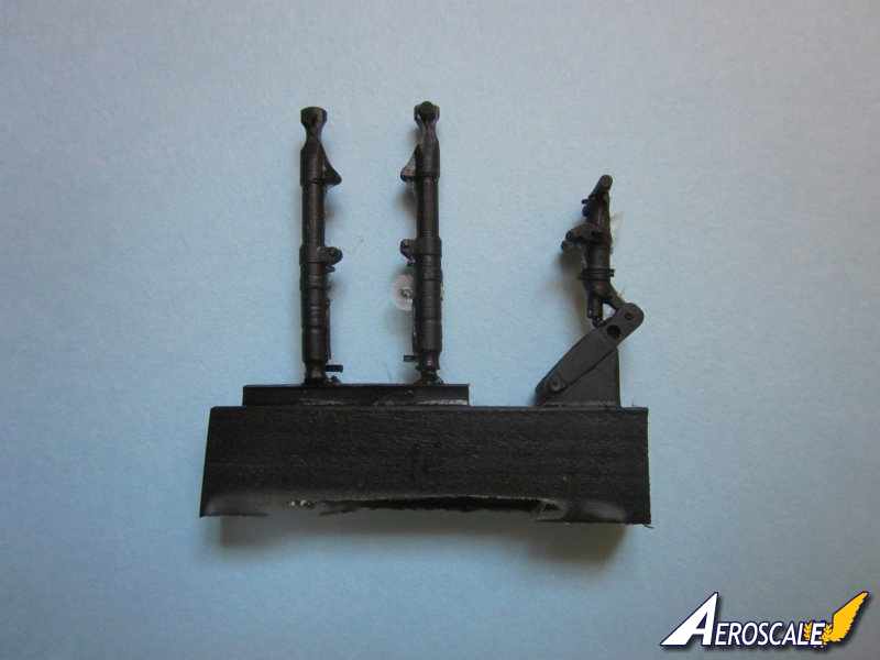
Undercarriage: the legs of the undercarriage are cast in black resin, which feels harder than the green coloured resin on the rest of the kits components. The detail is excellent on the nose gear. There are some detailed photo etched torque links to add to the legs of the main gear. There are two sets of one piece wheels supplied, with a choice of different spoke patterns. The detail on the wheels is superb including brake drums and tyre treads. The undercarriage doors are detailed on the inside. To finish off there are actuator rods to add to the doors and undercarriage legs.
It's worth noting that CMR have provided colour references for all the internal parts that are visible.
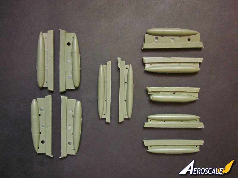
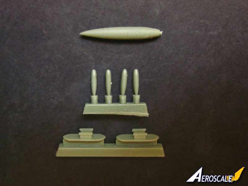
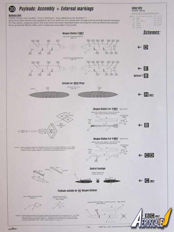
Payload: in other words thing to hang from the Scimitar F-1. There is a good variety of payload included by CMR:
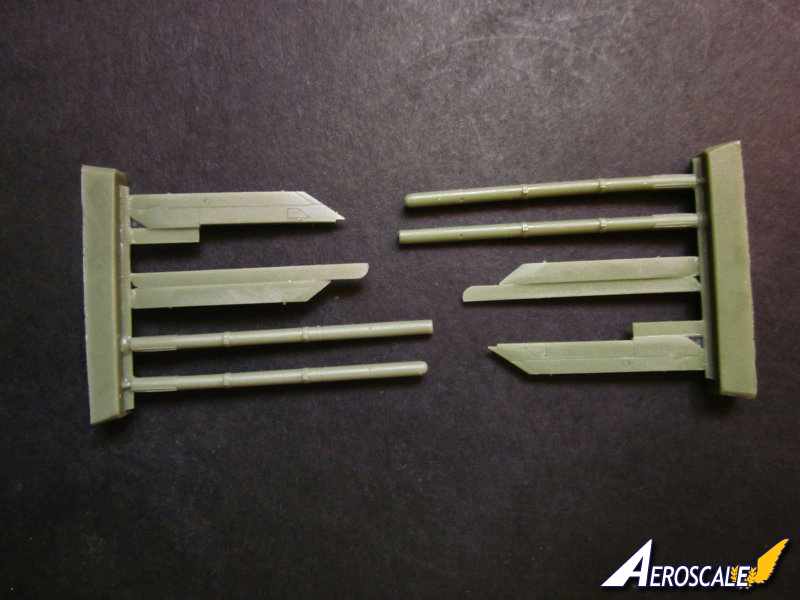
-'Drop Tank' Mod.5072 Weapons Pylons.
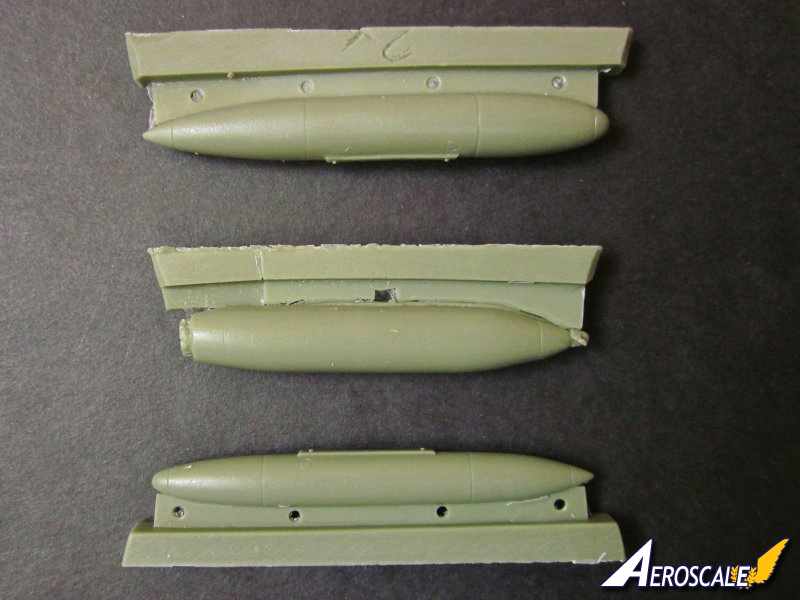
-4 x 100 Gallon drop tanks.
-2 x 150 Gallon drop tanks.
-4 x 200 Gallon drop tanks.
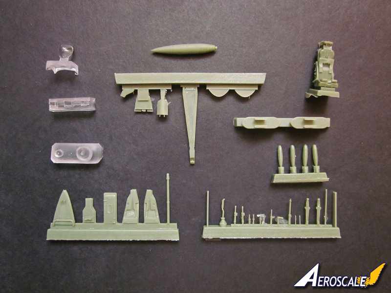
-1 x Mk.20 HDU flight refelling pod.
-2 x AIM- 9B 'Sidewinder' training round, fins are photo etched.
-2 x AIM-1A/9B 'Sidewinder', fins are photo etched.
-2 x Sidewinder (Aero 3B) Launcher Adaptor Rail.
-1 x Ventral camera pod.
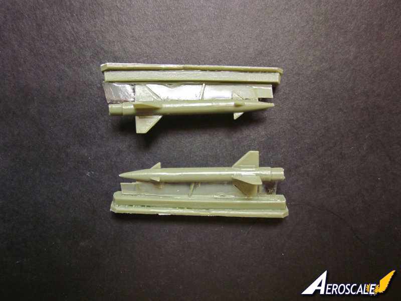
-2 x 'Bullpup' ASM-N-7A missiles and aero launcher.
-2 x 25lb Twin Bomb Carriers.
-4 x 25lb No.2, Mk.1, Practice Bombs.
The refueling pod is a great inclusion and it has some fine detail such as the turbine blades at the front and the folded basket tucked into the rear of the pod. The 'Bullpup' air to ground missiles are one piece with very thin fins. The separate ventral camera pod has a photo etched carrier to construct. All the items of payload have their own decals.
The quality of the resin castings generally is superb. After looking over every inch of the parts I counted three small pin prick holes in the resin surface. These can be easily dealt with using filler or correcting fluid. CMR certainly know their stuff when it comes to using resin to create models.
Photo Etched Parts: the two sheets are produced by Eduard. The coloured fret has some incredible detail on it. Included with the photo etched parts is a jig for setting the photo etched fins for the sidewinder missiles. The blade aerials are all photo etched parts.
Masks: the Kabuki masks are just for the canopy, and are produced by Eduard. Some additional masking is required for the top of the canopy, use liquid masks or the off cuts from the Kabuki tape.
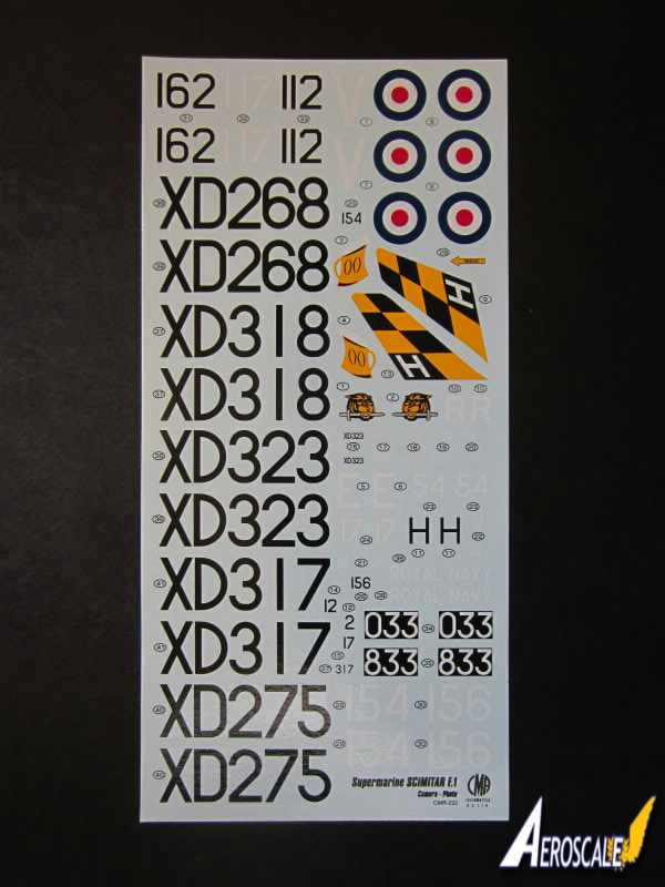
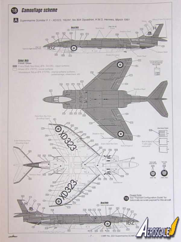
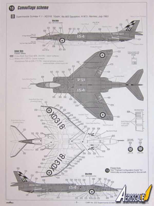
Markings: all aircraft are painted extra dark sea grey [FS 36118] on the upper surfaces and white [FS 17875] under surfaces. A - XD323, 162/H, No 804 Sq., HMS Hermes, March 1961. B - XD318, 154/H, No 803 Sq., HMS Hermes, July 1961. C - XD268, 156/V, ex No 803 Sq, A&AEE, Weapons Flight, West Freugh, 1961. D - XD275, 117/E, No 800B Flight, HMS Eagle, April 1966. E - XD317, 112/R, No 800 Sq, HMS Ark Royal, May 1963. F - XD317, Airwork Fleet Requirement Unit, Hurn, November 1966. G - XD317, 033, Airwork Fleet Requirement Unit, Hurn, November 1967. H - XD317, 833, Airwork Fleet Requirement Unit, Hurn, May 1969.
No there is no printing error, 'XD317' is depicted with four different markings
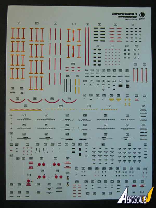
Decals: the silk screen printed decals look very good. Colour density and registration is excellent with minimal amount of carrier film. The black and yellow fin checks of 'XD 318' are supplied as decals. The large serial numbers applied to the lower wing surfaces need to be applied before installing the wing weapon pylons. There are quite a few stencils to apply.
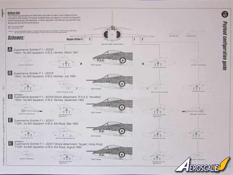
Instruction: The graphics by Zdenek and Ben Dyer are excellent. The diagrams are exploded black line with very helpful written details. The eight schemes provided are according to CMR historically accurate and are sequenced from A to H. Also included are payload configuration guides which suggest a particular payload for each individual aircraft carried on a particular date. For each scheme CMR provide port and starboard profile views of the aircraft and also a upper and lower plan views. Also on the camouflage guidance sheets are individual drawings of the airbrakes doors a wheels.
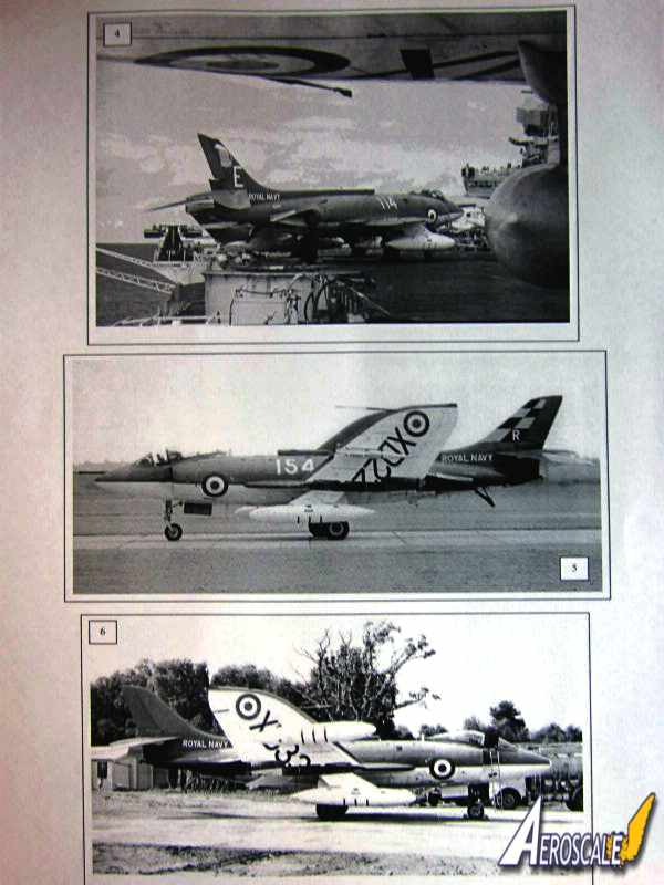
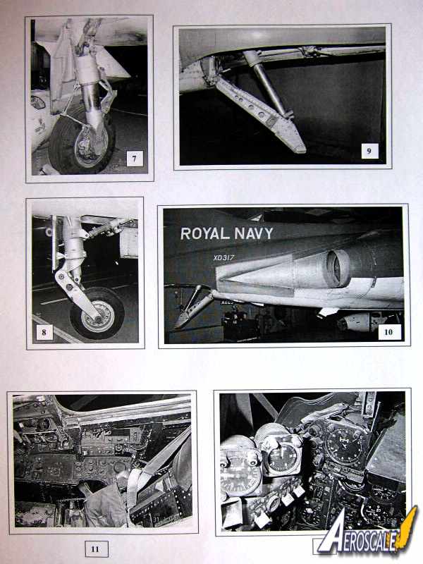
As already mentioned the black and white images included with this release are a real bonus. There are six 'in action' images mostly of the aircraft taxiing or parked. There are also fifteen 'close up' images of the Scimitar. The close up images help enormously when used in conjunction with the building instructions. The payload guides are also very useful and provide dates that are historically accurate for each of the camouflage schemes. Where ever possible they are based on photographic evidence of the individual aircraft or other Squadron aircraft serving operationally at the same time.
CMR instructions and information have to be some of the best in the business.
Conclusions
This is another excellent release from CMR and one that will appeal to all you Fleet Air Arm aircraft modelers out there. The construction looks straight forward and there are not too many parts, thanks to some clever design work. The kit certainly looks accurate to my eyes and CMR have captured the subtle lines of this big fighter/reconnaissance aircraft very well. Some experience with resin kits will be useful with this release, but I think this would be a good kit for beginners to cut their teeth on their first resin kit. Nice one CMR
SUMMARY
Highs: Far too many to mention.Lows: Not spotted anything so far.Verdict: Very highly recommended.
Our Thanks to Czech Master Resin! This item was provided by them for the purpose of having it reviewed on this KitMaker Network site. If you would like your kit, book, or product reviewed, please contact us.


Comments