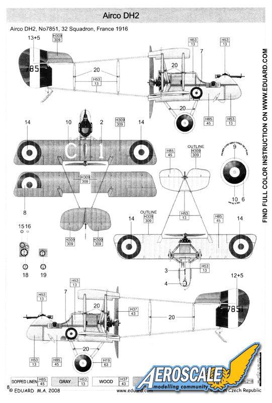
The lack of a reliable synchronized gun gear in 1915 was the main reason that the Royal Flying Corps considered pusher type aircraft were for military operations. The Germans had gained a decided advantage in the air war with the Fokker gun gear that armed that companys Eindecker type aircraft. The100 hp Gnome Monosoupape (mono-soo-pop) powered, single seat scout named the DH 2 was the brain child of the Aircraft Manufacturing Companys Mr. Geoffrey de Havilland. In truth it was simply a scaled down version of his earlier 100 - 120 hp Beardmore powered, two seat pusher, the DH1a. The completed prototype appeared at Hendon on 1 June, 1915. It was sent to France on 26 July and on 9 August 1915 armed with a forward firing Lewis gun the prototype #4732 was going through front line evaluations while assigned to 5 Sqdn RFC. It was brought down behind German lines by a crew from No. 2 Marine Flieger Abteilung based at Moorsele. Rebuilt in the Moorsele workshops and put through German evaluations she gave up her secrets. Nevertheless the DH 2 went into production and served as the mainstay of several RFC units well into early 1917. The squadron selected to be the first equipped with the DH 2 was 24 Sqdn RFC. They arrived at their assigned base at Bertangles France on 10 February 1916.
The story,
On a black and stormy night, in the Czech Republic, lightning ripped the skies near castle Eduard. Deep in the bowels of the old north tower, the dark robed, design wizards huddled over a boiling cauldron and poured liquid styrene into their newest molds. In the eerie half light of the whirring, hissing and crackling machinery, magic wands are waved, switches are thrown and an aged hand spreads techno-dust. Then a gaunt, pale, half crazed figure in a medical smock steps up to the mold box and holds his stethoscope to the outer casing. As he listens he commands, silence ! A wizard reaches for the 1923 Philco radio and turns down the blasts of Edgar Winters Frankenstein. Moments later, suddenly the doctor cries out, Its Alive!!! . . . its alive!!! Thus another scale wonder is born.
Kit history,
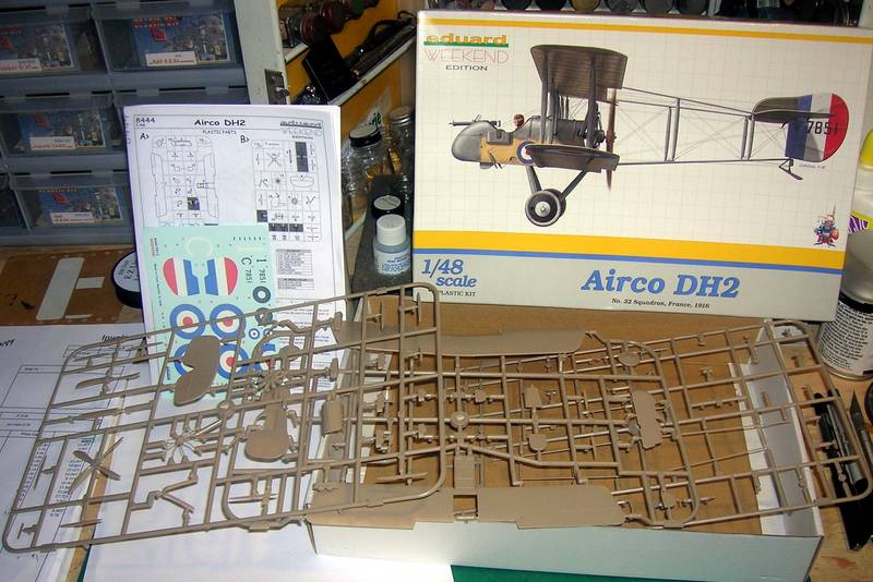
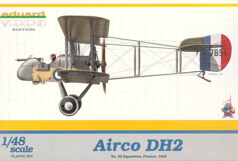
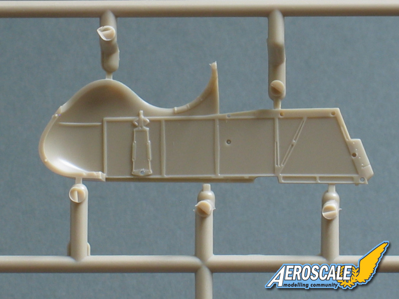
The long awaited, highly anticipated De Havilland DH 2 (basic kit #8093) arrived in hobby stores during early March of 2005. The Profi-pack kit (#8094) arrived at the end of the same month. The plastic parts are all we have come to expect from a company that has led in the manufacture of WWI aviation modeling subjects. If you plan to rig your build begin with general clean up, seam removal and pre drilling all rigging pilot holes. In this build we will discusss the current Weekend kit issue #8444.
The build,
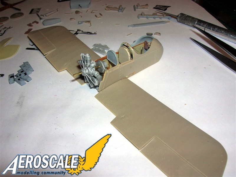
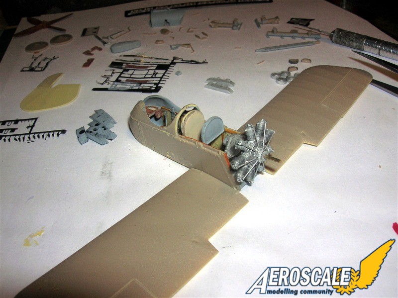
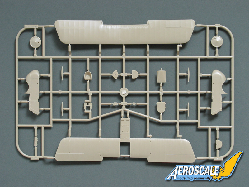
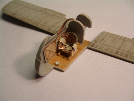
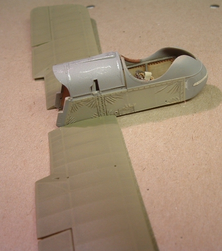
Step 1. Begins with the cockpit interior components based on the fuselage floor extension on the lower wing (PP A 2.) The compass (PP C 26 & decal) fit into the floors forward notch. The control column and its stabilizer bar (PP C 12) are to be flanked by seat supports (PP C 22 X2) and the seat (PP A 6 or PE 23) will sit on these. The lap belt should be added as shown in ther review images as attached to the internal framework. In the fuselage side(PP A 4), the rudder bar (PP C 15) and its support block (PP C 19)are to fit in the forward most floor notch. Then add the rear cockpit screen (PP A 13) and the main oil tank facade (PP A 9.) Note that the instructions advise you only dry fit (dont glue) the engine belly panel (PP A 12.) The rotary engine cradle (PP A 8) can be added here. These last items are to be trapped between the fuselage sides (PP A 4 & 14) when the sides are united and glued together.
Step 2. There are three types of instrument panel arrangements provided. Two of these provide for in cockpit stowage of Lewis ammunition drums. There is a map providing decal locations for each arrangement. The layout appears to have the decals representing the instrument faces assigned letters to direct their placements. They are clock; altimeter; air speed indicator; tachometer. Next you add this shelf assembly and the and the transverse bar (PP C 23) for the elevator actuations. Later the bar ends (PP C 3 X 2) will be added and if rigged will connect to the actuation horns on the horizontal tail surfaces (PP B 4.) Check steps 9-11 especially the rigging diagrams. Finally the upper rear cowling (PP B 16), cockpit and lower wing assemblies are united. On this part the forward most filler cap is for the main fuel tank and the rear most filler cap is for the oil tank.
Step 3. Adds the air induction tube (PP C 25) in the top of the upper rear cowling.
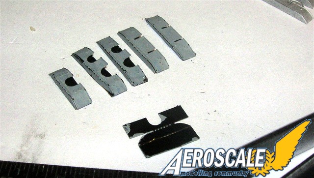
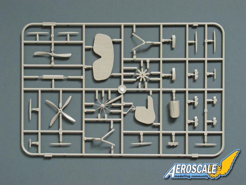
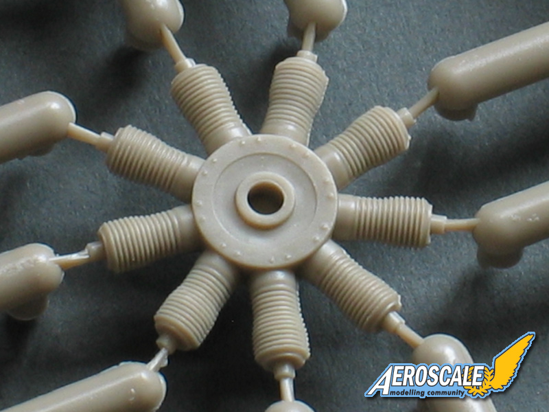
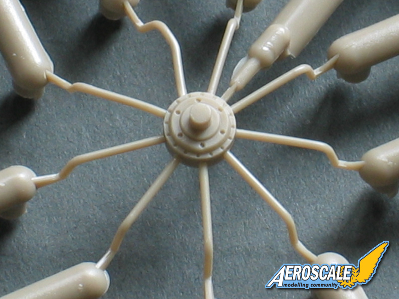
Step 4. The Gnome Monosoupape (mono-soo-pop) 100hp rotary engine (PP B 6) has the crank case cover / push rods (PP B 13) assembly and induction tube (PP C 20) added. The term monosoupape means single valve. In some cases these rotaries were replaced by LeRhône 110hp 9j and Clerget 110hp types. Usually the Eduard Profi-pack kits provide photoetch push rods of a more in-scale nature. Not with this kit. I replaced the plastic ones with cut and blackened brass rod types. Use your Xacto knife and cut a small slice through the center of the nipple at the top of the cylinder heads to wedge the push rod control arm (PE 17 X 9) in place while the glue dries. Check your references.
Step 5. Assembles the landing gear. (PP A 3 X2, B 3, 5 & 14) Note the correct layout of the landing gear legs and do not attempt to rig yet. The completed landing gear assembly should be installed on the fuselage and all joints thoroughly set before rigging.
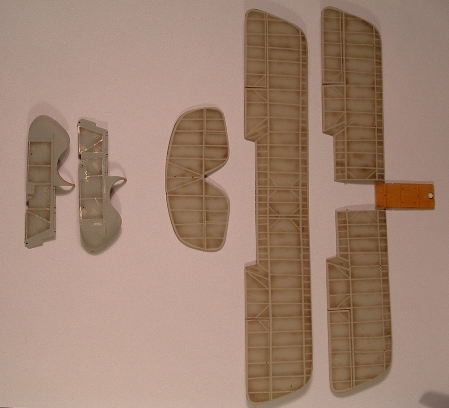
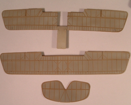
Step 6. Uniting wings and struts is not as tricky as one might think. Since the interplane struts (PP B 1 X 8) are all installed vertically without incidence (forward angles) or stagger (lateral angles.) I recommend attaching the interplane struts to the top wing and when partially dry complete the attachment to the lower wing using a temporary jig made from childrens Lego blocks. The gravity feed fuel tank (B 7 & 8) appears to be one of the 5 & 3/4 gallon versions. You will note that there are several variations on the location of the gravity feed fuel tank. Also for those of you unfamiliar with the type the outer wing panels upper and lower were both interchangeable. In several cases British cockades were seen in unusual positions because of in the field replacements. Check your references.
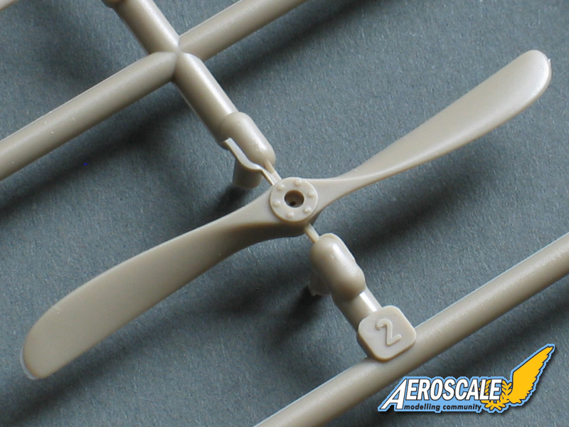
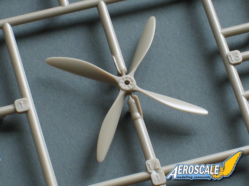
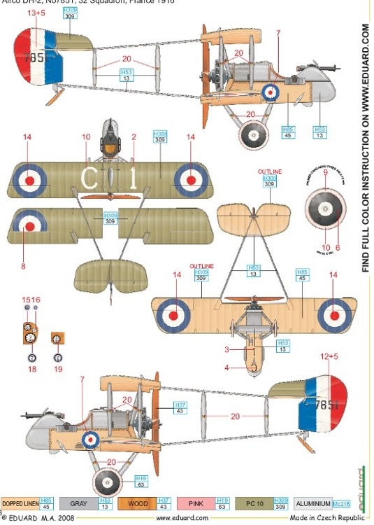
Step 7. I recommend adding the rotary engine next then add the landing gear and finally the propeller to the fuselage assembly. Do not forget the lower wing brace (PP B 11.) The two bladed propeller (PP B 2) was the early standard. After The last weeks of January 1916 it seems the four bladed propeller (PP B 12) began being installed on the DH 2 types. Other existing machines were retrofitted as they became available for maintenance. The smaller compass fairing (PP C 16) was seen on some of the 1st production types #5916 - 6015. The larger compass fairing (PP C 2) began appearing with in later part of the first and then on into the other subsequent production airframes. Components were at times swapped for what was available during maintenance.
Step 8. The seemingly delicate tail surfaces (PP B 4 & 15, C 11 X 2 , 14 X 4) and booms (PP B 10, C 17 & 18 ) gain a very reasonable amount of strength when assembled and thoroughly dry. The only failing is that Eduard doesnt give you a clue as to the method of for attaching the criss-crossed rigging wire for the tail unit. (About four photoetch double ended turnbuckles would help.) I have put a good deal of thought into this and have come up with several methods. For the sake of the average builder lets keep it simple. The thickness of the wings allows the Cats cradle method of rigging to be attained easily. Drilling holes into the wings for monofilament then anchoring the ends in place with cyanoacrylate glues. The tail booms were metal on the original aircraft but here your working with plastic. DO NOT drill into the plastic tail booms!!!
So the reasonable option is to anchor your rigging material ends to the upper and lower ends of the vertical struts on the boom sides (PP C 17 & 18) closest to the rotary engine. These will be angled to the direction that they will travel to the next locator hole. With these ends anchored securely in this area the other ends can be pulled through the locator holes in the wings and horizontal tail surfaces. Next I recommend attaching the booms to their wing slots first. Then add the tail surfaces. Then at this time complete the rigging. Anchor your loose ends by pulling them taut with the free weight of wooden clothes pins and applying a small drop of cyanoacrylate glue to these rigging pilot holes in the wings. Let thoroughly dry before you release the clothes pins and clip the excess rigging lines flush with the wing surface.
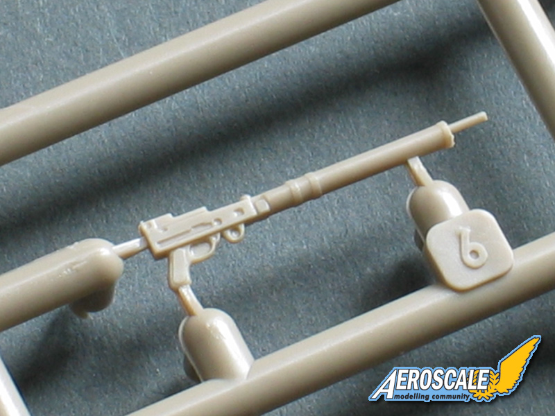
Step 9. Shows two different possible routs for the fuel tank plumbing ( C 4, 5 & 24.) Then there is the Lewis gun Mk II ( PP C 6, .) gun pivot ( PP C 13 & ) also a 47 round ammunition drum (PP C 1 ) or the 97 round ammunition drum (PP C 21 ) and external storage bins for those ammo drums (PE 28, 33 & 34.) Also add the elevator actuation pivots (PP C 3 X2.) See rigging diagram. The double drums or 97 round types were developed about November - December 1915. Records give the credit to its creation to either Major Hawker and Air Mechanic French of No. 24 Squadron RFC or members of the armoury section of No. 18 Squadron RFC.
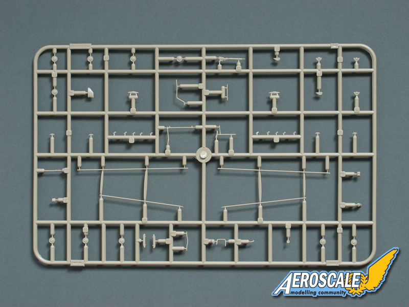
Step 10. Rigging tables for upper surface view fore to aft. In truth you should have accomplished the rigging as you progress through your build. The most difficult part of this build is getting the rigging right from the elevators to the cockpit nacelle. The rigging between the wings is easily accomplished by step 6 if you have prepped well. Always remember to leave the finishing of the upper wing top surface and the lower wing under surface until you have done all you want to with the rigging. Then finish these surfaces by filling the rigging pilot holes, sanding flush and paint. The smaller the holes the less to repair. The landing gear is the next area to rig.
Step 11. Rigging tables for under surface view fore to aft.
Step 12. Rigging between the wings. Note the doubled wires in half of the locations. This is typical for many British fighters of the time. Again careful planning in the early stages helps the modeler in drilling pilot the holes for the rigging.
references,
Cross & Cockade Intl. Vol. 20 #1 1989 Part 1.Cross & Cockade Intl. Vol. 20 #3 1989 Part 2.
Cross & Cockade Intl. Vol. 21 #3 1990 Part 3.
Cross & Cockade Intl. Vol. 22 #1 1991 Part 4.
Cross & Cockade Intl. Vol. 22 #4 1991 Part 5.
The de Havilland D.H.2" by J. M. Bruce, Profile Publications , 1966.
The Royal Flying Corps in WWI by R. Rimell, Vintage Warbirds #1, Osprey Pub. 1985
Thorpe Parks Pusher by J. Hall, Aeroplane Monthly Pp. 72-75 1980.
* The term ...worlds first true fighter aeroplane was coined by WWI aviation Guru Ray Rimell.
Comments,
I have to give it to Eduard, they do great kits. The DH 2 is a beauty right out of the box. Their marketing strategy says that only about 8% of all modelers world wide are rib and rivet counters. Then the rest are the builder / collectors and finally the casual builders. Ask yourself what kind of modeler are you? Whatever you decide remember above all to have fun. Model On!
SUMMARY
Highs: Excellent details straight out of the box.Lows: The tailbooms should never have been plastic. The decals in my example are faded as if they have been on the aircraft for a long period. On the website they are bright and clean.Verdict: This is a fine kit that with a little patience will give you a great build.
Our Thanks to Eduard! This item was provided by them for the purpose of having it reviewed on this KitMaker Network site. If you would like your kit, book, or product reviewed, please contact us.
About Stephen T. Lawson (JackFlash) FROM: COLORADO, UNITED STATES
I was building Off topic jet age kits at the age of 7. I remember building my first WWI kit way back in 1964-5 at the age of 8-9. Hundreds of 1/72 scale Revell and Airfix kits later my eyes started to change and I wanted to do more detail. With the advent of DML / Dragon and Eduard I sold off my ...
Try some of the Aviattic decals. One fellow used cellophane painted white to apply to a skeletal wing then laid down the Aviattic over the dried cellphane (already on the wing).
Cheers Stephen
I'd probably just use clear decal film painted on the reverse side. I doubt I'll ever go for a weave-effect in 1:48 - as you know, I'm still to be convinced of the authenticity in scales like this. It's a modelling vogue I'm happy to eschew, as shading and texturing more than do the trick for me.
All the best
Rowan
I painted over the Aviattic finish to match the paint on the rest of the build's upper & lower surfaces. Its the quality of the decals that lets them be manipulated.
Model Cellar figure combination set #48007. WWI British RFC Pilot and mechanic. Though this set could include RAF as well.
As you may note I have changed the poses of each befitting my story line of the DH 2.
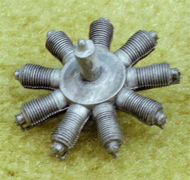
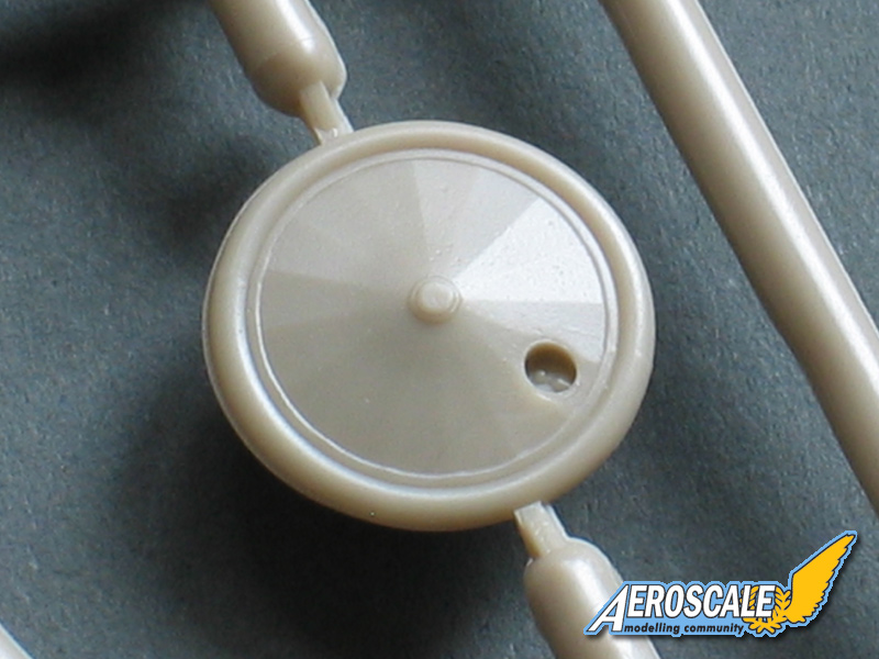
Eduard kit item representing the Gnome 100hp rotary. Front face.
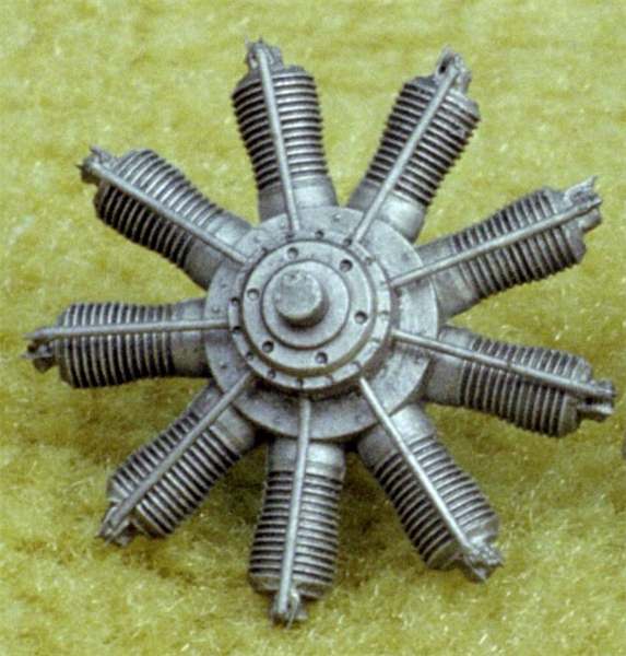
Rosemont resin Gnome 100hp rotary front face.
Eduard kit item representing the Gnome 100hp rotary.
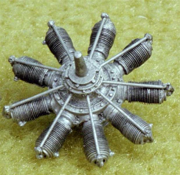
Rosemont resin Gnome rear face
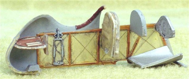
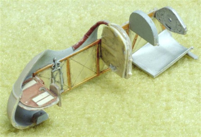
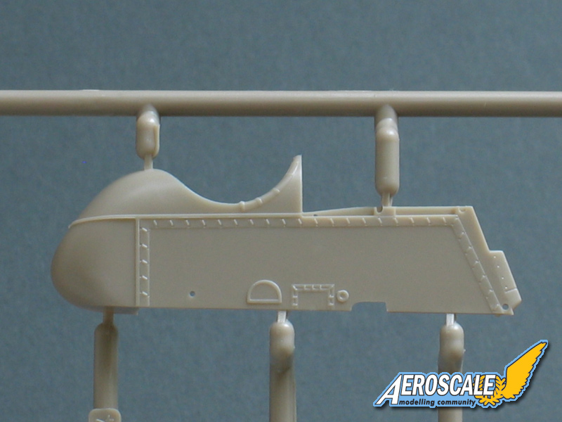
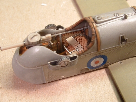
The pilot's right half of the fuselage with some paint and bulk heads in place. Note the fuel cel facade has a rippled section of resin added to represent the canvas bag that shrouded the original.
The pilot's right half of the fuselage with some paint and bulk heads in place. Note the fuel cel facade has a rippled section of resin added to represent the canvas bag that shrouded the original.
The pilot's right half of the fuselage with some paint and bulk heads in place. Note the fuel cel facade has a rippled section of resin added to represent the canvas bag that shrouded the original.
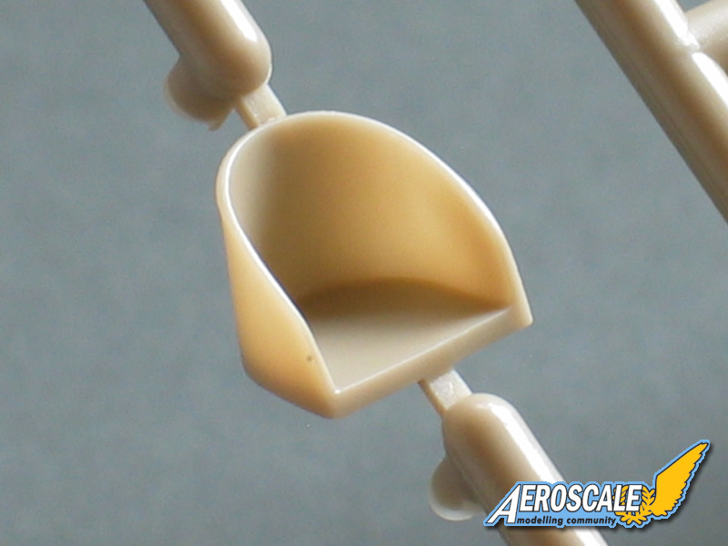
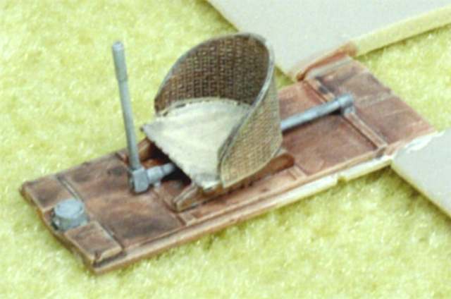
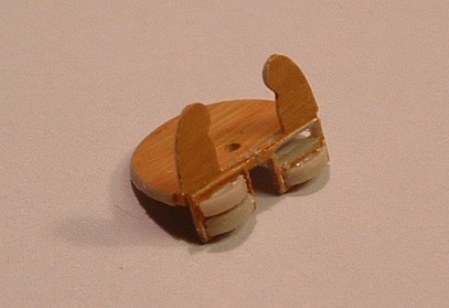
Seat in the lower portion of the image is scratchbuilt by Lars Qvarfordt. See his special Feature on this build. In the upper portion is the old PE seat from the profipack kit.
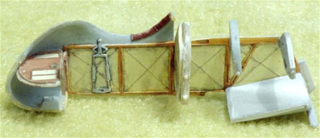
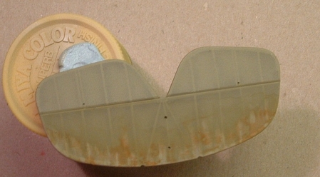
The lower wing / cockpit floor with a PE seat from the old profipack set.
The lower wing / cockpit floor with a PE seat from the old profipack set.
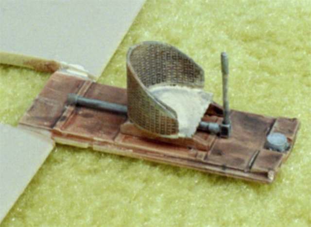
the kit instrument and ammo drum storage shelf was altered by Lars Qvarfordt
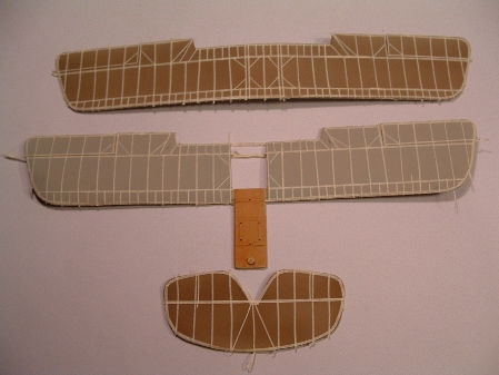
Lars Qvarfordt has a unique form of painting spreshading & rib highlights.
Lars Qvarfordt has a unique form of painting spreshading & rib highlights.
Lars Qvarfordt has a unique form of painting spreshading & rib highlights.
Lars Qvarfordt has a unique form of painting spreshading & rib highlights.
Lars Qvarfordt has a unique form of painting spreshading & rib highlights.
Lars Qvarfordt has a unique form of painting spreshading & rib highlights.
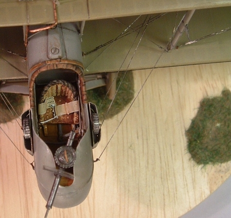
The cockpit of Larsa's DH 2. The only error you could point out was the underside of the ammo drums are too smooth. You would be able to see a portion the ammunition on the real aircraft.


Comments