Introduction
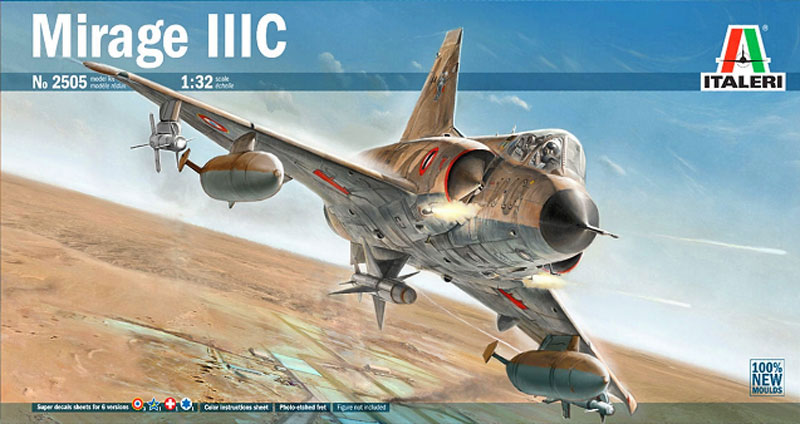
The Dassault Mirage IIIC was a Mach 2 capable fighter-interceptor developed in the late 1950s-early '60s for the French Air Force. It was the first European design to exceed Mach 2 in level flight and quickly became an export success eventually being used by Israel, South Africa, and Switzerland among others and for low-level interdiction missions as well as interceptions. Dassualt proved to be open to modifications proposed by customers and design changes eventually led to versions such as the IIIE, III0, V, 50, and 2000 as well as versions developed by other countries. Fast, relatively easy to fly and maintain, and adaptable, the Mirage family became probably the greatest post-war success for the French aviation industry. Its greatest success as well as its best advertisement was its use by the Israeli Air Force in the 1967 Six Day War, where Mirages led the attack on Egyptian air fields that devastated the Egyptian Air Force and led to almost complete Israeli air superiority throughout that conflict.
The Kit
Italeris announcement that they were releasing a new tool 1/32 Mirage IIIC was greeted with mixed feelings by the modeling community. While many were very happy to hear of a new big scale Mirage to replace the ancient and venerable Revell effort, there were questions. Would this be instead of or in addition to the announced Kinetic effort? Why the IIIC rather than the more numerous and widespread IIIE/V series? Most importantly: Italeri? Would this be a stronger effort than the F-104?
I, for one, was very happy to hear it and started bugging our illustrious publisher about reviewing it immediately. When I was a kid (lo these many years ago) the exploits of the Israeli Air Force in the Six Day War of 1967 were front page news and held me spellbound. Ive made numerous attempts at Mirages since then including the Heller and Eduard 1/48 kits. There was no way I was going to pass up a 1/32 version. Id heard mixed reviews of Italeris F-104 but what the heck; Im a modeler, right? At first the previews didnt show an IAF version in the decals, but I figured I had enough in the decal store to deal with that. Then the final production info was revealed and there was the famous 159, the highest scoring Mirage of them all. The deal was done.
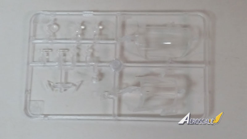
The first previews I saw of the model had me a bit worried. There were short shots of the parts, missing decal instructions, and worst of all the way Italeri chose to pack the clear parts. Since the box is larger than the sprues, Italeri put a smaller box inside to take up space, and then packed the clear parts on top of that. This put them perilously close to the top of the box and in danger of being crushed. Sure enough, some people found the windscreen and/or canopy cracked or broken on opening their new kits. Happily, that didnt happen to me and my clear parts looked great, as did the rest of the kit.
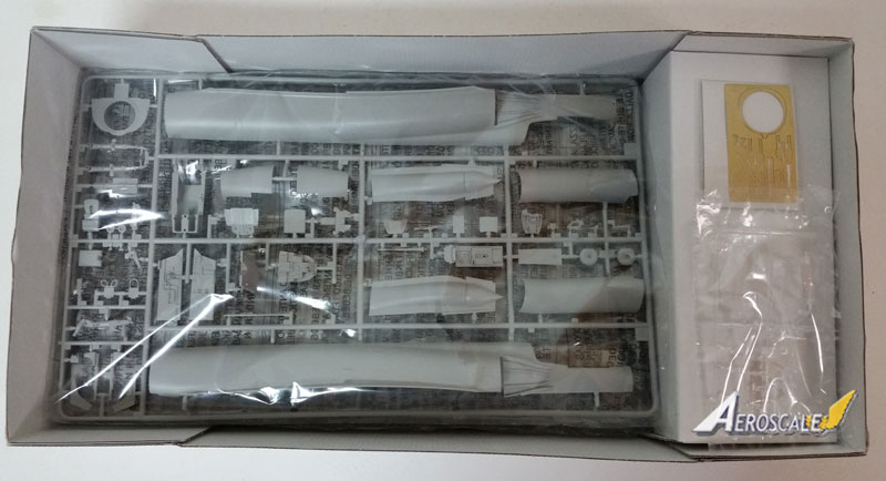
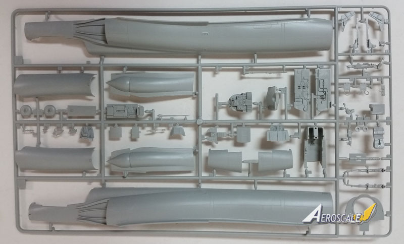
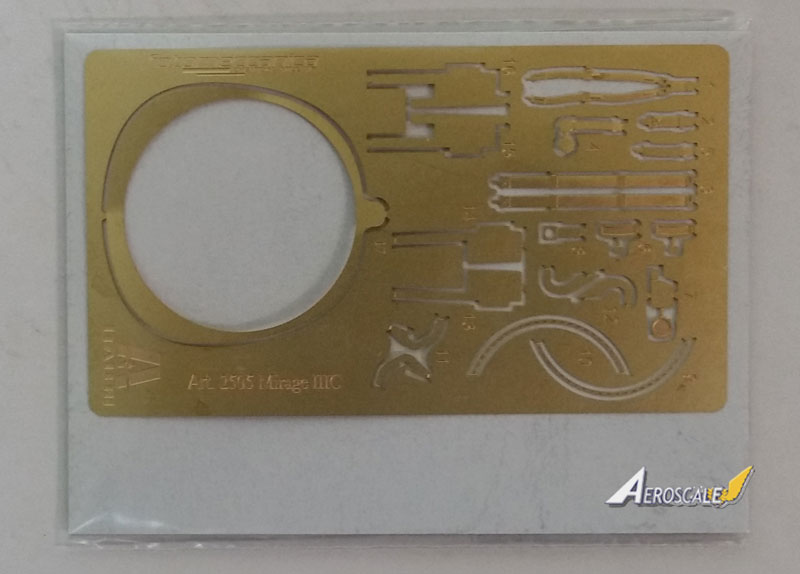
The gray parts are on five large sprues with one duplicated that holds stores, wheels, engine cart parts, etc. They have good detailing with slightly soft but acceptable panel lines and no sign of any mad riveter (though there are some, they are restrained). Theres a slight texture to the plastic but it disappears under a coat of paint or primer. If youre worried about it, the plastic is soft and easy to polish smooth. Theres also a sheet of photo-etched brass with seat harnesses, gear door hinges and other various parts; nothing major but a nice addition. Decals are spread across two large sheets and include very colorful markings for three French, one South African, one Swiss, and one Israeli aircraft. The decals are, of course, by Cartograph and look excellent on the paper. The instructions have full color renderings for each scheme, though the actual construction steps are in gray-scale. For more detail on the kit and what it contains, see
Jim Starkweather's Unboxing video.
Israeli Air Force Mirage/Shahak 59
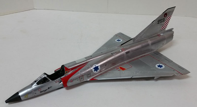
There was, of course, no question of which Mirage I was going to build, though there were some decisions to make. The markings supplied in the kit are for Mirage 59 as it appeared in the early 70s, during the War of Attrition. 10 of the aircrafts eventual 13 kills are shown applied to the nose which would put probably between March and July, 1970 (with one extra kill). This is based on a fairly well known photo of the airplane easily found online. Heres a list of the aircrafts actual kills (from Mirage and Nesher Aces by Shlomo Aloni, Osprey Aircraft of the Aces #59):
14/7/66 SAF MiG-21 Yoram Agmon cannon First Mirage/Shahak kill
5/6/67 EAF Il-14 Ukab Gonen cannon Six Day War
6/6/67 EAF MiG-19 Uri Shachar cannon
7/7/69 EAF MiG-21 Oded Marom cannon War of Attrition
20/7/69 EAF MiG-17 Giora Yoeli cannon
11/9/69 EAF Su-7 Giora Epstein cannon
11/11/69 EAF MiG-21 Yair Sela cannon
4/1/70 EAF MiG-21 Oded Marom cannon
6/3/70 EAF MiG-21 Yiftach Spector cannon
10/7/70 EAF MiG-21 Israel Baharav AIM-9B
10/7/70 EAF MiG-21 Israel Baharav cannon
13/9/73 SAF MiG-21 Avraham Salmon AIM-9D
6/10/73 EAF AS-5 Eitan Karmi cannon Yom Kippur War
After its last kill in 1973, 59 crashed on take-off and was rebuilt, at which time it was upgraded with the later Atar 9C engine. For those who want to make an Israeli aircraft but are allergic to bare-metal finishes, as of mid July, 1971 59 was camouflaged in the four color Israeli scheme. It would have had basically the same markings (though there were some changes in stenciling and it had 12 kll markings) so can mainly be made out of the box. It did not seem to have carried the large yellow/black ID triangles until after being re-engined, so you cant have everything.
A note on Israeli tail numbers: At the time the Mirage was acquired in 1962 or shortly thereafter Israel started adding spurious first digits to aircraft numbers. This was almost certainly to fool unfriendly countries into believing there were more Mirages on inventory than there actually were. While Ive seen various explanations as to what those numbers signified (such as each squadron having a specific number), looking at pictures doesnt bear them out. They seem pretty random to me. Theyre almost always referred to in the literature by their last two digits. I havent seen 59 with just 59 on the tail.
The Build
I generally go by the instructions in my build articles and will here as well. When I deviate from the order indicated in my actual build, Ill let you know. The instructions themselves are typical drawings with arrows and can be less than clear. Painting colors are called out as you go with letters that refer to a table at the front. It may be helpful to copy this to make it easier to check with as you go along. Paints colors are given by name and in FS numbers and Italeri paint numbers.
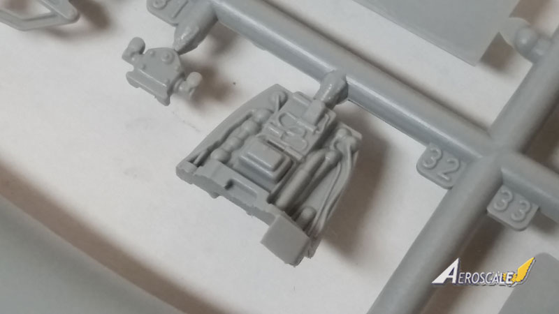
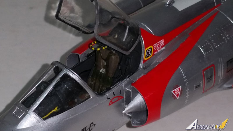
- Steps 1 and 2 cover the ejection seat. In this case Italeri has done a fairly nice job with the Martin Baker Mk.BRM4 though its a bit basic. The photo etch harnesses are actually nicer than we often seen in kits and dress it up nicely. Note that the kit includes the double pull handles used on later Mirage variants and gives the first indication that more may be coming. The IIIC used the single semi circle handle as called out in the instructions.
Right away we run into the fact that this is Italeri. Construction of the seat isnt really positive and is a little fiddly. The instructions are not terribly clear either. So, as will become a theme, test fitting before glue is a must. I deviated somewhat from the called out colors based on some online photos Ive seen, but I think seat colors generally are not uniform. See the pictures for my result.
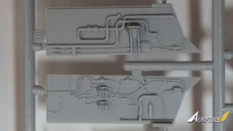
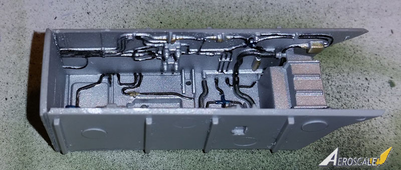
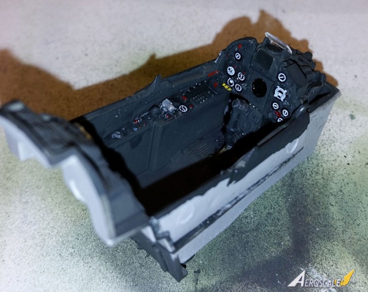
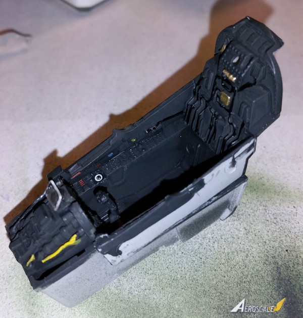
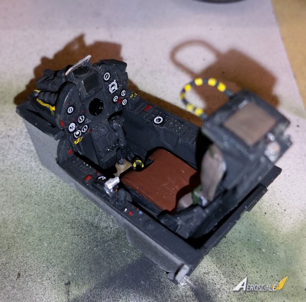
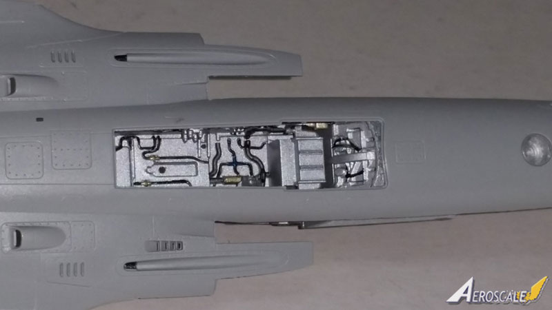
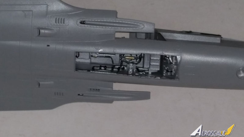
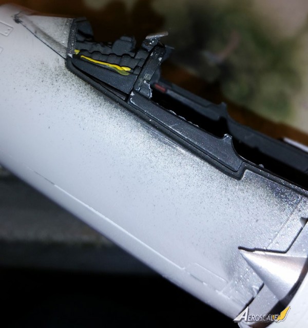
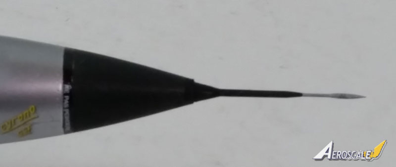
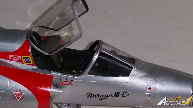
- Steps 3-5 put the cockpit together. Mirage cockpits were black and this is whats called out in the instructions, but they dont show any detail painting and I picked some things out as I saw in online photos and, frankly, with a little license. I used Tamiya NATO black for the base color and painted some of the plumbing and wiring in Semi-Gloss black for contrast and added some color here and there as well.
The instrument panel has come in for negative comments online and, indeed, its not the correct layout for Israeli Mirages. But Dassault made a lot of changes to the basic aircraft based on the customers requests and it may be the correct setup for someone else. Its also possibly for a later Mirage version. My bigger problem with it was a complete lack of instrument detail and no decals either. I used some old instrument decals I have hanging around and think it looks fairly effective.
The gunsight and throttle do actually look correct as, largely, do the side panels though the detail is a bit soft. Again, construction is not particularly positive so take care. The instrument panel slots into the side panels so make sure you do this or youll have trouble fitting the windscreen later (ask me how I know!) Otherwise thing are basically butt-joined, so again test fit and allow everything time to dry.
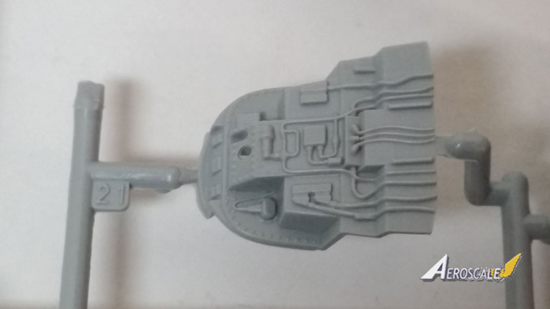
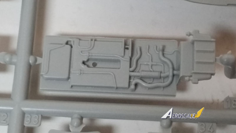
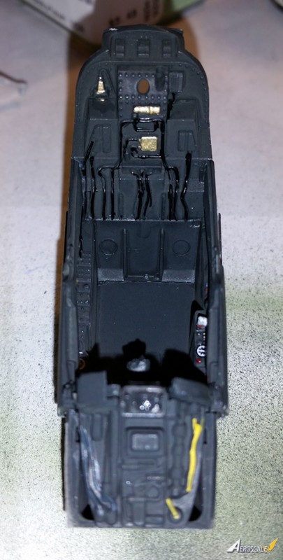
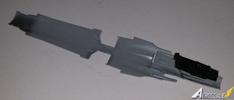
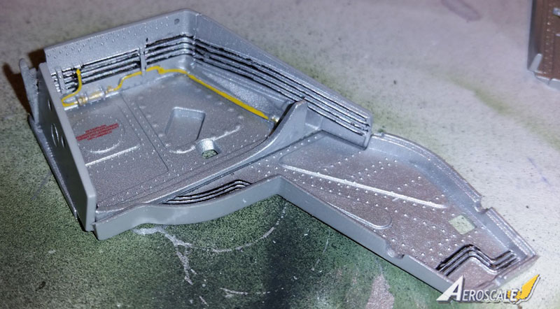
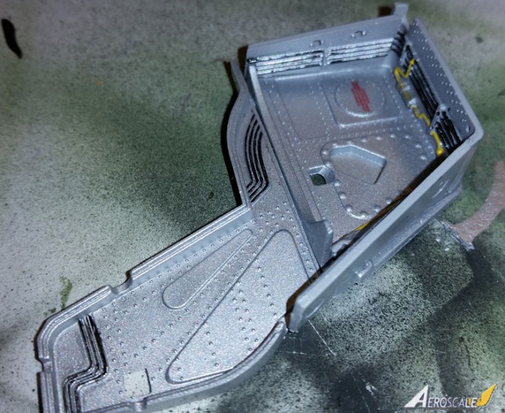
- Step 6 includes the nose gear well and inside of the lower fuselage. The gear well is, as weve come to expect, a little fiddly and I found a small gap at the back that was easily covered with a piece of plastic strip. Detail inside is nice, if it doesnt entirely line up along the joins, and makes things look suitably busy. Be sure to align everything with the rear bulkhead of the cockpit so it all fits together. Its not as hard as it looks and fits well to the lower fuselage.
Here is the one place I added to what was in the kit. The clear part (1E) that fits in the nose was the landing light. I didnt like the fact that its just a hole with nothing behind it, so I made up a simple light well using some tube and sheet plastic and a lens that will otherwise be excess to requirement. It may not be right, but its better than nothing. If you do this be sure to keep it short as the cockpit installs above it.
Parts 12B and 13B are the 30mm guns. While small they are pre-drilled, which is nice. Dont forget to install them! Also be sure to open the indicated holes for parts to be installed later. One of call outs is labeled Configuration F/G which refers to a series of drawings towards the end of the instructions laying out stores configurations. You might want to decide now which stores youll be using and keep that letter in mind as this will come up frequently in the directions.
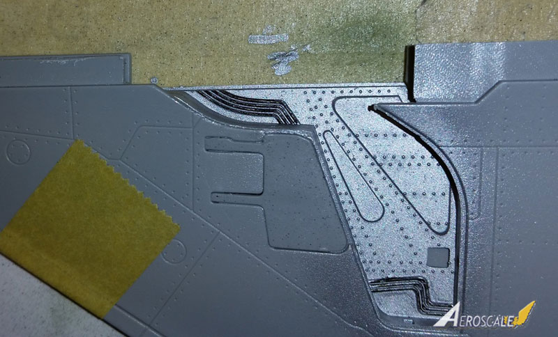
- Step 7 is labeled A which I dont quite understand as theres no 7B. Anyway, this is part of the main gear well. Youre going to find this shocking, but assembly here is not too positive (!) so take care. I found that starting with parts 1 and 2C helped to line things up.
I installed these finished wells on to the bottom fuselage as shown and found later that this was a mistake. When I tried to install the wings thingse just werent going to fit. My advice here is to label these left and right and put them aside for later. If you install them WITH the wings, everything goes much better.
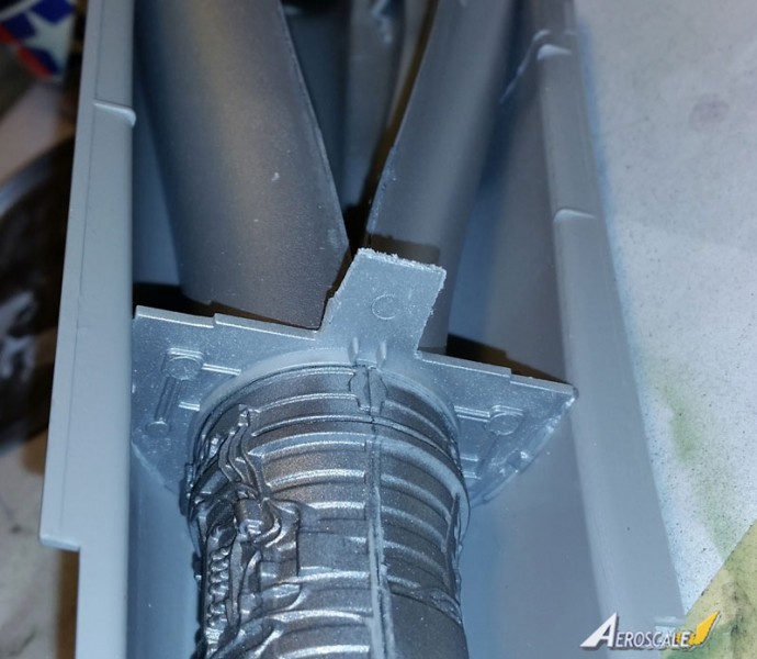
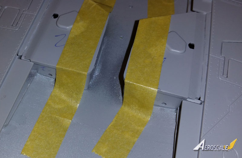
- Step 8(B? Why?) is the intake trunks. These are full length and actually look pretty good when completed but the instructions arent too clear. See my attached photos for the correct configuration. Italeri shows you should cut off the small top and bottom pegs at the inside front of the ramps and this is correct (no idea why these are there since later versions had different intakes). They also show that cutting off the middle peg is an alternative and direct you to steps 9, 12, and 13. There are alternative parts here but no indication of when to use them. As far as Ive been able to determine, Israeli Shahaks seem to have the small center pegs as molded and not the alternative parts, but I cant say about other air forces.
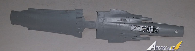
- Step 9 takes us to the main fuselage halves and starts the intake installation. Again, watch for holes/slots you have to open. The instructions call for opening slots in the upper port fuselage for antennae to be added later so I did so. Unfortunately when I looked at photos I found that Israeli aircraft didnt have those and I should have left them closed. Well, mine has non-standard equipment. The intake trunk is a little tricky but the inset shows how it should look and it actually fit rather well when put in the right place.
By the way, the instructions here refer to the intake trunks as B as they were constructed in Step 8B. This makes a certain amount of sense but why they couldnt have been referred to as 8 is not really clear to me.
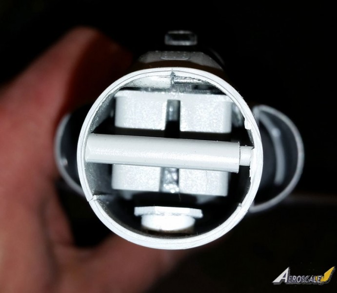
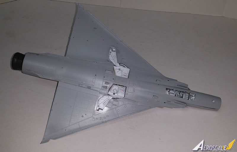
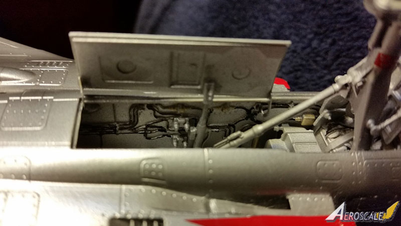
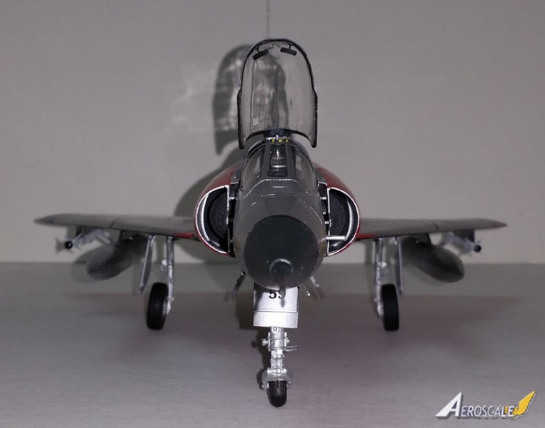
- Step 10 (C, here we go again) is the engine. Detail isnt bad here but will be mostly unseen. No parts are added to the outside of the engine though there is a lot molded in. There is an engine cart later but this leads to a common problem with these kinds of feature. Theres only one engine front and burner can. So if you leave the engine out for display, youll have a fairly conspicuous (and devoid of detail) hole through your airplane. Needless to say, I installed the engine. Be careful with the placement of parts 25 and 26B, the flame holder parts; refer to my pictures for the correct lineup. 25B has a tab that sticks out the back and fits into a slot in the attachment point on the inside of the engine. The arrows in the instructions are again not overly clear. Another problem I ran into hear (and elsewhere) is that the sprue attachment points are often on join surfaces even where there are slots or ledges. This can make for tricky clean up. Check carefully where a part will go before you cut it off the sprue so you dont damage anything.
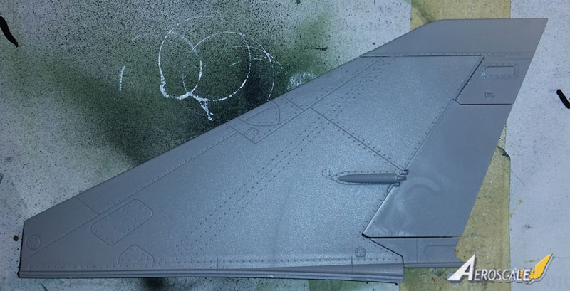
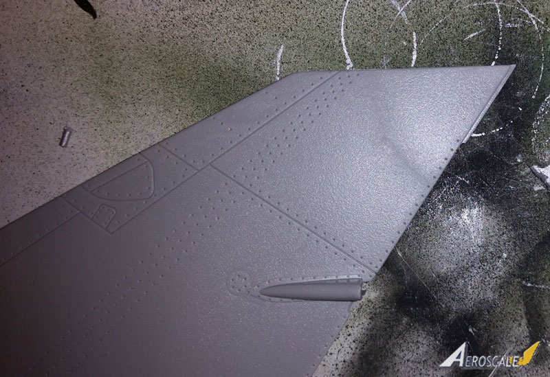
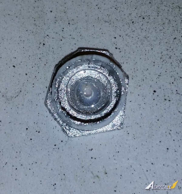
- Step 11 (D. I mean, really) is the tail. Everything goes together fine here though the forward extension (parts 20 and 23B) is not a particularly positive fit. There are mold ejection circles inside the forward extension halves and you might need to clean these up to ensure the parts fit together cleanly (I did). I left the lights (parts 4E) off for now. The rudder is separate and can be posed off center though Ive never seen a photo of one on a Mirage on the ground deflected to one side or the other. There is a small ridge on the top of part 3C, the port half of the tail fin. Be careful not to sand that off while cleaning up the sprue attachment, its supposed to be there.
- Step 12 (E1 and 2 depending on engine installation) joins the two upper fuselage halves. For some reason you open those antennae slots in the starboard half here rather than back in step 9. Whatever. It also shows you opening two holes in the forward fuselage. These are for the boarding ladder, so if you dont want to use that, dont open those holes. I didnt glue the very forward part of the fuselage halves (in front of the cockpit) together yet to give me wiggle room if necessary later.
The engine is NOT a positive fit into the fuselage. The only places where it actually attaches are at the front and into a photo etch bulkhead at the rear that is flimsy and isnt particularly strongly attached to the rear fuselage. A little extra engineering might have helped here. This will get better when the tail burner can and tail cone are added later.
- Step 14(F, sigh) is the port wing. Italeri has you install the main gear legs now but I determined that with a little careful wiggling they can be left off now and jammed in there later. Just be sure to glue the wells in solid so they dont split open when you add the gear.
The speed brakes are separate parts and can be positioned open but there are no wells, so if you open them all the way there will just be holes. Also be careful when cleaning up the arms on part 35B and (42B on the starboard side), the lower speed brakes. These have a bit of a bulge on one of the arms thats supposed to be there but thats also where a sprue attachment point is. Compare them to the cutouts in the wing to see what the shape should be.
Check and see if the stores configuration youre going for uses the inner wing pylons and open those holes now if it does. Also you have to install the formation lights in the upper wings now. They seem to be pretty tight to the lower wing when its all put together so you dont have to worry about poking them out when removing the liquid mask you put on them later for painting.
- Step 15(G) is the starboard wing and goes together the same as above, only the other side, I suppose.
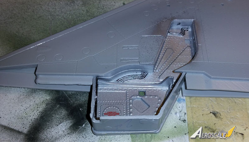
- Step 16 brings the upper and lower fuselages and wings together, so its a big one (if simple looking in the instructions.) I ran into a major problem here getting the wings in around the earlier installed inner wheel wells. I managed to pry the wells loose from the lower fuselage and glued them directly to the outer wells in the wings, test fitting against the lower fuselage to make sure it all lined up. Once those dried I glued the wing and wheel wells onto the lower fuselage first, then added the upper fuselage. It all lined up pretty well at that point, I was happy to see. At least the wings/fuselage did. The forward fuselage was not so nice and I may have over sanded cleaning up sprue attachments on the join surfaces of the lower fuselage. Strip plastic to the rescue, and not for the last time!
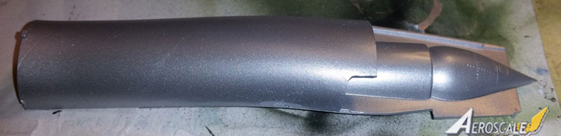
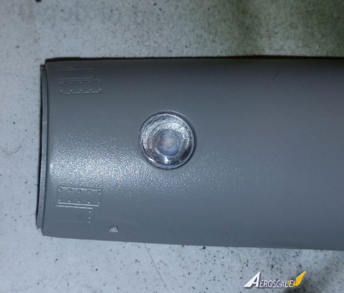
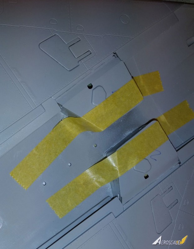
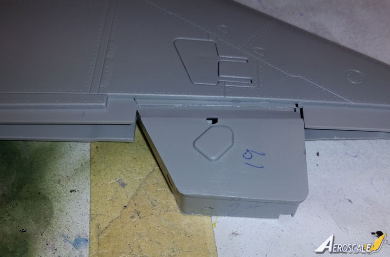
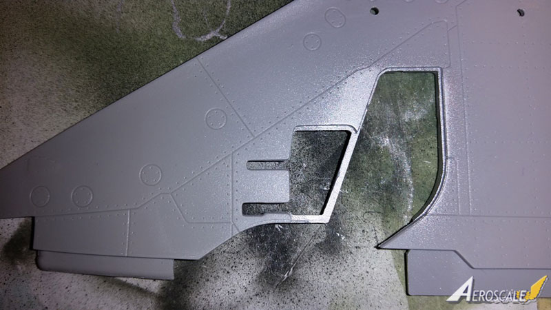
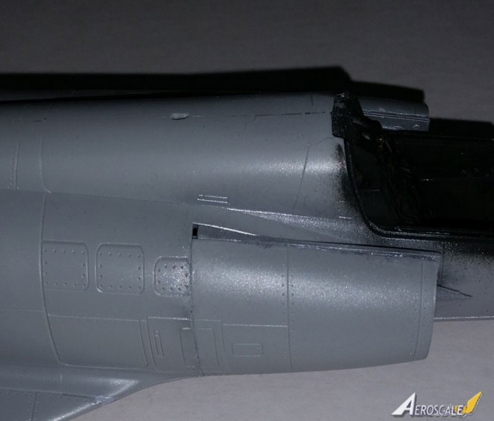
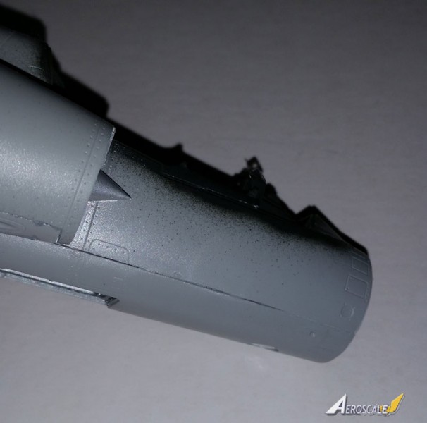
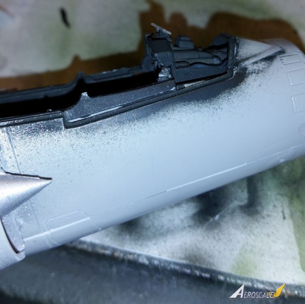
- Step 17 is an inset where you add the intakes and nose. These were a bit of a chore. The intakes arent too terrible but the join line runs right through an access hatch (see pictures) and there were some nasty gaps underneath especially that required strip plastic help. The radome just plain doesnt fit at all (see pics). I used a 20mm spreader bar in the forward fuselage to help round things out but it still required a fair amount of sanding. That nose section is just plain bigger around than the fuselage and thats just the way it is.
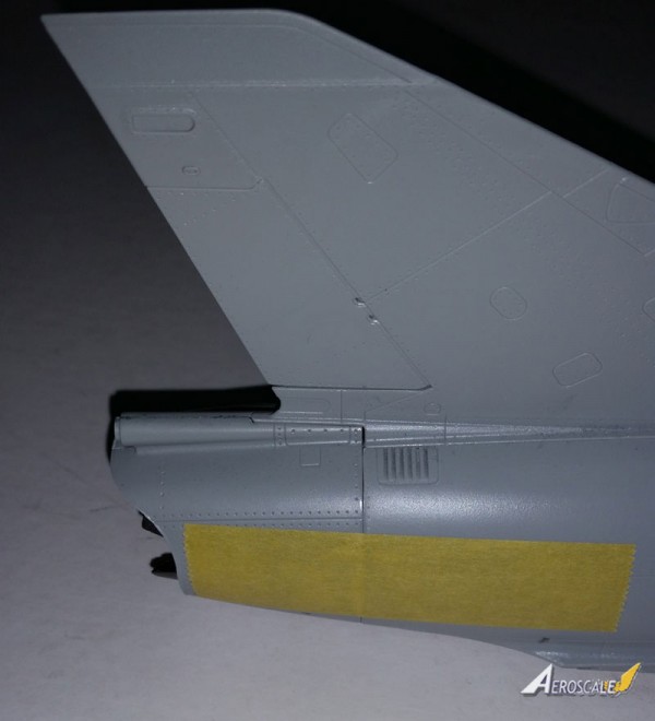
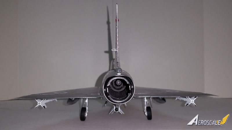
- Step 18 comes in two varieties depending on whether youve installed the engine or left it out. Both cover the burner can and tail cone. The burner can includes two small perforated etched metal strips that go around the inside of the very end. Theyre a little tricky to install but add to the look when done. The tail cone itself, parts 46 and 47B, is quite thin, making it hard to clean up the seam along the bottom, especially if you want to replace any rivet detail you sand off. Theyre so thin that they flex and re-open the seam. Part 9E is the tip of the parabrake housing and is, for some reason, clear. Ive never seen a light here and when I asked on line no one else said there was one either, so I painted over it. The tail cone doesnt fit spectacularly well to the fuselage, especially around the brake housing, so more strip plastic here.
- Step 19 is the installation of the control surfaces and their hinge fairings. Things fit pretty well here and they are positionable, though again Ive never noticed them in anything other than neutral on the ground. Note that the outer fairing has optional parts depending on whether you want a pylon there.
- Steps 20-24 are landing gear and I skipped these until after painting. Ill go through them here in the interest of consistency but now or later is up to you.
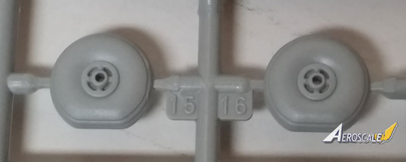
- Step 20 is the main gear. This isnt too bad in the scheme of things and goes together fairly well if not too positively. Be careful with the inner main wheel halves as there are two different varieties (again, pointing to a different version to come). 4D is correct for the Mirage IIIC. It is not made clear in the instructions what angle the gear legs should have and I have them too straight up and down. They should angle in slightly with the wheels closer to vertical than I have them (not straight vertical but less toed out than I did).
- Step 21 is the inner main gear doors and they are definitely fiddly. They only attach at the hinges so go slow and test fit. Once theyre installed, theyre not very sturdy so Id advise saving them until as late in the build as you can so theres less chance of breaking them off.
- Steps 22 and 23 show how to install the gear doors closed. Theres no pilot included, so youre kind of on your own there.
- Step 24 is the nose gear and here the word fiddly really comes into its own. This whole thing, but especially the doors, is way over-engineered in my opinion. The doors use photo etch hinges and in the case of the main and top doors those hinges are pretty much the only things holding them on. This is not even close to as easy as it sounds so take your time and let things set up solid, or as solid as possible.
An accuracy note: Mirage IIICs did not have landing lights on the nose gear strut as depicted in the kit. I filled the slot here and used one of the lenses in my scratch built housing in the nose (see step 6). Those gear mounted lights were added (I believe) with the IIIE and V, so that may be another indication of things to come.
- Step 25 has you add some photo etch fairings between the intakes and the fuselage. These are supposed to be there but the fit is in no way spectacular so be careful when bending and fitting. Have a look at the painting drawings for an idea where they should be positioned as the instructions here are not the clearest. I added these before painting which I think was the right thing to do. I also added the scoops shown here but not the antennae or probes until after painting.
- Step 26 starts the stores and weapons construction. You are given 1300 liter drop tanks as well as 500 liter supersonic versions. You also have an odd munition labeled the JL100R tank/rocket combo that Ive never seen before (which means nothing, really, I certainly havent seen everything). Theres also the Matra R530 which was a classic early Mirage weapon. While the body of the missile is duplicated on the sprues, you only get one set of fins (the Mirage only carried one of these at a time anyway).
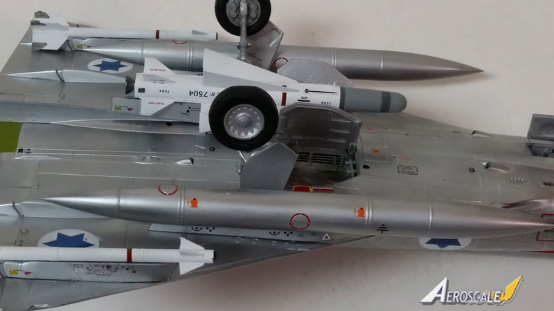
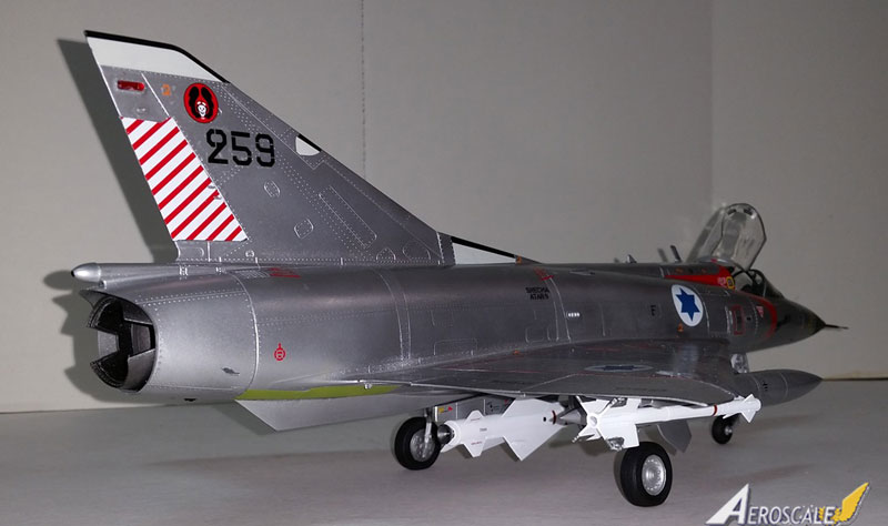
After step 26 is the page with the different stores configurations, 8 in all which I think is pretty good! Full marks to Italeri here as it would be hard to find 1/32 French underwing stores in the aftermarket. I went for a modified F config. which is a classic air-intercept set up. Ill explain the modification in a minute. Again, I didnt actually add the stores until after painting and decaling.
- Step 27 shows a modification to the under fuselage strake, part 36B, that youll have to make if youre mounting the Matra R530. Its pretty straightforward, you just have to cut a chunk off in front to make room for the Matras pylon. You would also add a couple of probes to the tail here though I left them off until after painting (just dont forget to go back and add them later).
- Step 28 shows the addition of the various tanks depending on which you choose. I went for the supersonic tanks because, what the hey, theyre cool!
- Step 29 Here the Sidewinders or Matra R550 Magic AIMs are added. In 1967 the Israelis didnt have AIM-9s (as mentioned above) but used their own home-grown Shafrirs. These looked very similar to Sidewinders but were shorter and had less angled forward fins. I cut the AIM-9s at the tail and nose and filed back the forward stabs for close enough Shafrirs and mounted them directly to the pylons with no adapter rails as the Sidewinders used. I followed a picture in the Osprey Mirage and Nesher Aces book on this and it looks close enough to me!
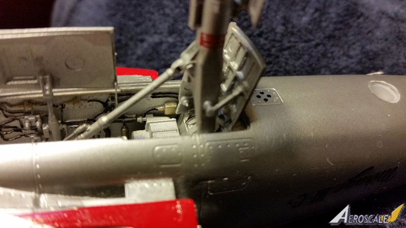
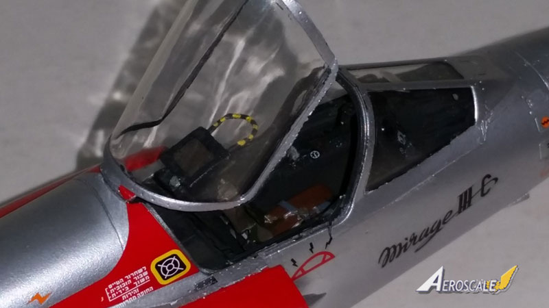
- Step 30 has you adding the windscreen and some upper fuselage antennae and scoops. I left the antennae off until after painting (as earlier pointed out, I should have left them off altogether) but added the windscreen. Id advise adding the small photo etch instruments inside the windscreen before adding it to the fuselage as theyre trick to get in there afterwards. If you were careful to get the cockpit side panels properly installed earlier, it will pay off here and youll find that the windscreen may be the best fitting part on the kit! Theres also a probe (part 22B) added to the forward fuselage here that I left off for now (but dont forget later.)
- Step 31 is busy with lots of sub-steps. Among other things you add the upper photo etch fairings between the intakes and the fuselage like the lower ones in step 25. I actually did all four there. Also added at this point is the canopy. Fit closed is good and I used the canopy (suitably masked) to cover the cockpit for painting. Fit open is NOT positive so be careful how you line it up and glue. I finally gave in and used CA glue here and got away with it without any fogging.
- Step 32 is the boarding ladder if you opened the holes for it earlier. I didnt use the ladder so cant comment on the fit. Interestingly Italeris illustration shows this being added with the canopy down. That could have been frustrating for the pilot.
And speaking of frustrating, this step also shows you adding the nose probe which I, of course, added last. Crowning finish, right? WRONG! That sucker is wildly smaller in diameter than the point it attaches to the radome. It looks awful. I havent gotten up the courage to do anything about it yet, but be warned.
- Steps 33 through 37 cover construction of the engine cart which I didnt build but looks complicated and Ill bet will have some dodgy construction (based on what Ive seen so far).
- Steps 38 and 39 just show alternative (engine in or out) display options, so I guess were done!
Finishing
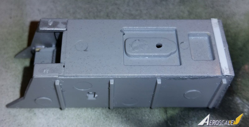
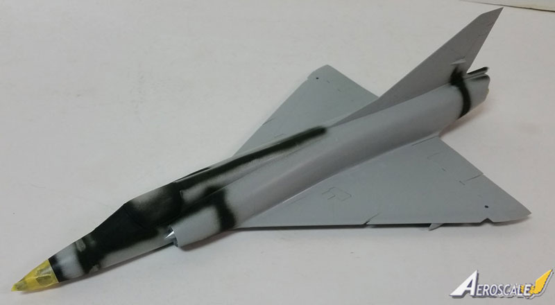
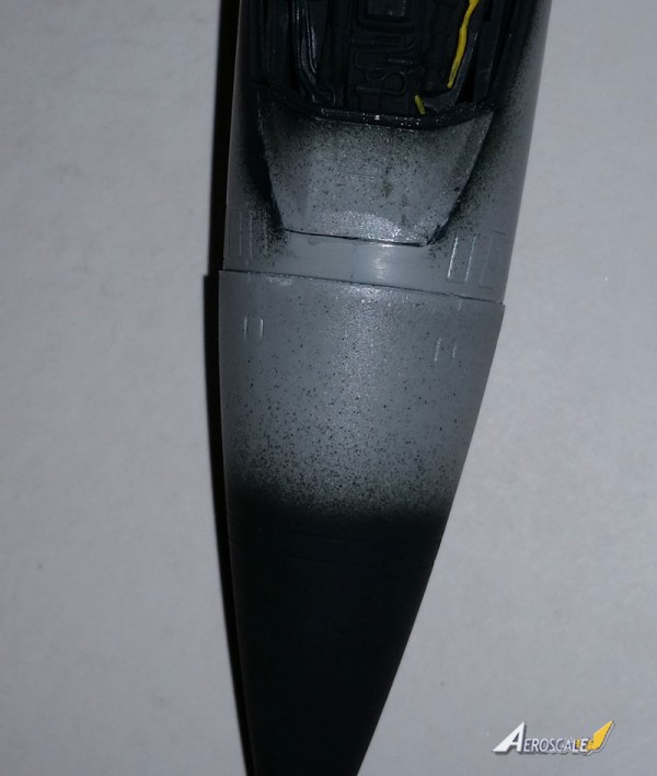
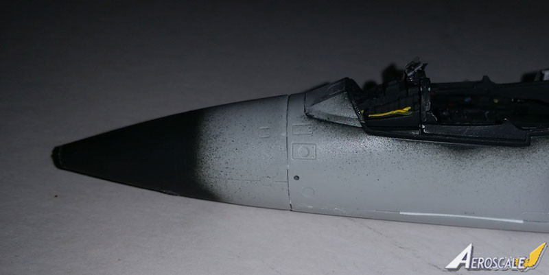
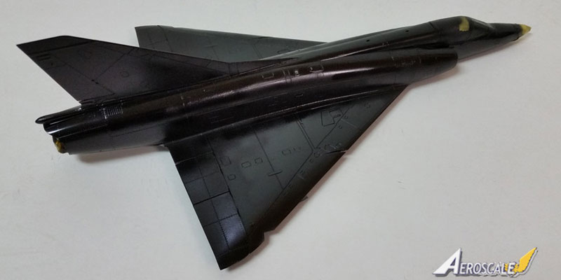
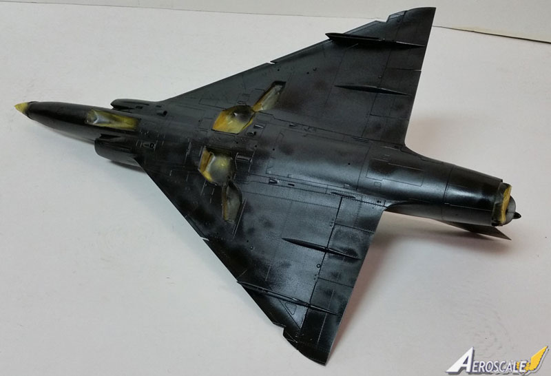
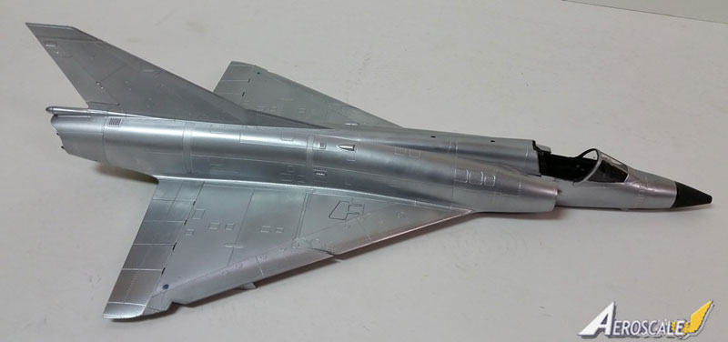
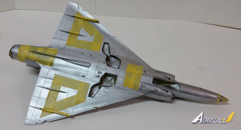
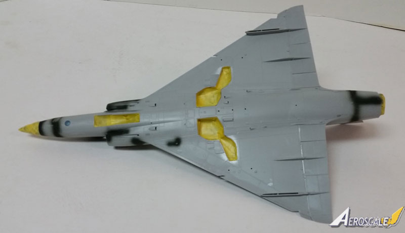
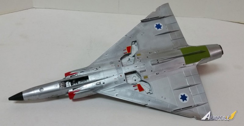
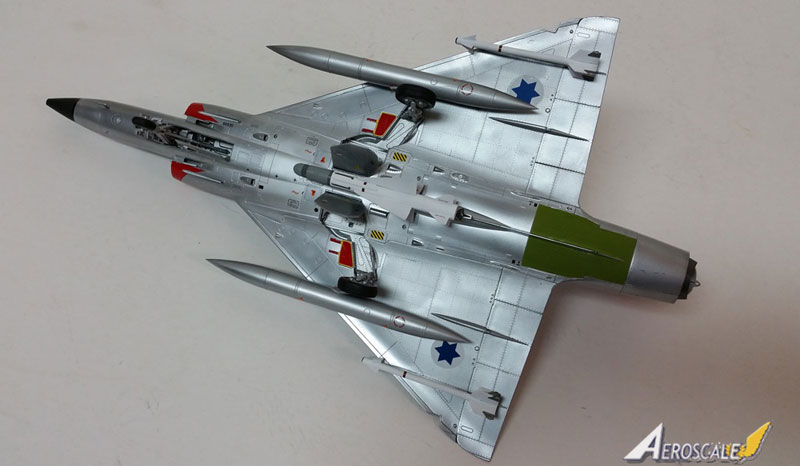
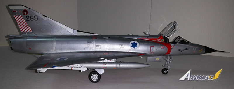
Mine was going to be in (gasp!) bare metal so I primed it with black first. I then used my favorite Floquil Bright Silver overall, masked off some panels, and polished it with some good old SNJ polishing powder. I like the way it turned out but feel free to use your own method. As far as I can tell Italeri is correct about that rear underside panel being zinc chromate green but wrong about the forward gun panel being zinc chromate yellow. I didnt do it anyway. Also I used Tamiya NATO black on the radome except for a pure black band around the aft end which matches the contrast Ive seen in photos.
The six marking options are shown in full color four view drawings as are the markings for the stores and pylons. For bare metal finish Ive found that photographs show the bright/dull aluminum colors as the opposite of what Italeri says. The decals are, as I said, Cartograph and are very nicely done. Some of the bigger ones are a little brittle, especially the flashes on the fronts of the intakes which are also not shaped correctly on the top. I used photos to cut mine once they were properly positioned on the model so you can use my pictures as guides if youre so inclined. I used MicroSol on the decals and it worked fine, though I might have used a touch of SolvaSet in a couple of places. The red/white stripes on the rudder for the Israeli version were a bit too large and needed trimming at the back, but thats better than too small! The kill marking decals show three green stars which would indicate all Syrian kills, which is wrong as a number for this aircraft were Egyptian and should only have two stars. Happily the first kill, the only one I used, was Syrian. Unhappily the stars should be equidistant from each other which is not how theyre depicted. Well, gotta draw the line somewhere.
Conclusion
I have a bad habit of emphasizing issues with kits in my reviews as I want to be sure to point out problem areas to my readers. One of my problems with this one was that I was working on the Tamiya Mosquito when I started it. Theres no comparison as far as engineering, fit, etc. But I dont see Tamiya taking on the Mirage IIIC and, on its own merits, this is a damn good kit. Good shape and detail and decent fit with no huge gaps, etc. Anyone with a few builds under their belt should be able to grapple with this one just fine. It reflects that Gallic flair and it sure fills a gap in major cold war combat aircraft. Ive always wanted a big scale Mirage and here it is! Thanks to Italeri for surprising us with this one. Buy and enjoy, I say; recommended!
Please remember, when contacting retailers or manufacturers, to mention that you saw their products highlighted here - on
Aeroscale.


Comments