_GOTOBOTTOM
World War II: Japan
Aircraft of Japan in WWII.
Hosted by Rowan Baylis
1/48 Hasegawa Ki 43 Hayabusa build
rdt1953
_VISITCOMMUNITY
New Jersey, United States
Joined: February 06, 2015
KitMaker: 1,098 posts
AeroScale: 900 posts
Posted: Monday, November 14, 2016 - 11:18 PM UTC
Hi to all - Starting a new build here- Hasegawa's early Oscar.


First order of business will be an attempt to improve the fuselage shape- along the top centerline of the fuselage the area from the firewall to the frame just aft of the wing root fillet has too much crown resulting in a "humpbacked" appearance that spoils the beautiful lines of this sleek airframe. I will be using photos and Kagero's excellent drawings from their TopDrawings series # 27. While I cannot vouch for their accuracy in shape 100 % they do measure perfectly in scale dimension and they visually present the correct line along the fuselage spine so they are good enough for this fussy guy.
More to follow - Cheers ! Richard

Antilles
_VISITCOMMUNITY
Nordrhein-Westfalen, Germany
Joined: March 22, 2015
KitMaker: 671 posts
AeroScale: 614 posts
Posted: Tuesday, November 15, 2016 - 03:14 AM UTC
Richard,
this will be a very nice project? Isn't this the bird You have posted earlier in a much bigger scale ?

Oliver
Joel_W
Staff MemberAssociate Editor
AUTOMODELER
_VISITCOMMUNITY
New York, United States
Joined: December 04, 2010
KitMaker: 11,666 posts
AeroScale: 7,410 posts
Posted: Tuesday, November 15, 2016 - 03:48 AM UTC
Richard,
I'll be pulling up a chair and following right along with your build.
Joel
Redhand
#522
_VISITCOMMUNITY
New Jersey, United States
Joined: January 20, 2013
KitMaker: 1,460 posts
AeroScale: 1,443 posts
Posted: Tuesday, November 15, 2016 - 04:03 AM UTC

Quoted Text

Richard,
I'll be pulling up a chair and following right along with your build.
Joel


Me too. A Ki-43-1 of the 64th Sentai?
rdt1953
_VISITCOMMUNITY
New Jersey, United States
Joined: February 06, 2015
KitMaker: 1,098 posts
AeroScale: 900 posts
Posted: Tuesday, November 15, 2016 - 04:08 AM UTC

Quoted Text

Richard,
this will be a very nice project? Isn't this the bird You have posted earlier in a much bigger scale ?

Oliver


Oliver - Indeed it is ! The big one is in the Ericson Collection in Madras , Oregon and is one of four rebuilt/restored from four Pacific wrecks . It is flown on a regular basis and represents a later Ki 43 II or III with clipped wing tips and powered by a P&W Twin Wasp. My build will be of the early Ki 43 with the beautiful ( to me ) rounded wingtips and two bladed prop. Hopefully it will not be dripping oil all over the model cabinet ! Thanks for looking - Richard
rdt1953
_VISITCOMMUNITY
New Jersey, United States
Joined: February 06, 2015
KitMaker: 1,098 posts
AeroScale: 900 posts
Posted: Tuesday, November 15, 2016 - 04:27 AM UTC

Quoted Text


Quoted Text

Richard,
I'll be pulling up a chair and following right along with your build.
Joel


Me too. A Ki-43-1 of the 64th Sentai?


Joel and Brian - Delighted to have you both aboard for yet another adventure ! This is getting to be a regular thing it seems and I couldn't be happier.
I haven't pinned down the unit and markings yet . I have a few aftermarket decal sets to pick from. I'm leaning towards a heavily weathered look - possibly CBI or late war home defense . This build may eventually wind up in a diorama with the Hucks truck so it may have a seated pilot figure - if not , then a full on cockpit detail may happen. I've got to try to fix or at least improve the shape first and I believe I'm on the way to a solution. Thanks for the interest-

Richard
Redhand
#522
_VISITCOMMUNITY
New Jersey, United States
Joined: January 20, 2013
KitMaker: 1,460 posts
AeroScale: 1,443 posts
Posted: Tuesday, November 15, 2016 - 05:27 AM UTC
Richard, I was surprised to learn that this Hasegawa kit has shape issues. Silly me, it never occurred to me to check. I don't think I have one of these kits but I do have a number of the Nichimo models of the – I and thought it looked pretty good. I also have that – II Fine Molds showing Manchukuo markings, but it was my first "natural metal" effort and it turned into a disaster. I would imagine that the early variant in late war markings is a fairly rare bird. I have a soft spot for the 64th Sentai in its prime, myself. Enemies of the Flying Tigers, the RAF in the CBI, and of course the Dutch.

Whatever you pick I'll be very interested in following it.
thegirl
_VISITCOMMUNITY
Alberta, Canada
Joined: January 19, 2008
KitMaker: 6,743 posts
AeroScale: 6,151 posts
Posted: Tuesday, November 15, 2016 - 06:06 AM UTC
I've got popcorn , pepsi ....I'm all set


Terri
Joel_W
Staff MemberAssociate Editor
AUTOMODELER
_VISITCOMMUNITY
New York, United States
Joined: December 04, 2010
KitMaker: 11,666 posts
AeroScale: 7,410 posts
Posted: Tuesday, November 15, 2016 - 11:36 PM UTC

Quoted Text

I've got popcorn , pepsi ....I'm all set


Terri


I think I'll seat right next to Terri, as I'm real found of popcorn and Pepsi.

Joel
rdt1953
_VISITCOMMUNITY
New Jersey, United States
Joined: February 06, 2015
KitMaker: 1,098 posts
AeroScale: 900 posts
Posted: Thursday, November 17, 2016 - 06:34 AM UTC
Brian - The shape issue was called to my attention some time ago on Nick Millmans' Aviation of Japan site - I tried to find that thread in order to post a link to it but I could not find it. I pride myself on being able to spot subtle differences in shape as my father and grandfather were both master
loftsmen and boatbuilders and I grew up learning how to read, develop and control shapes in three dimensions but this one got by me so I cannot take credit for noticing it. The FineMolds kit is fine and while I don't have one I am told the Nichimo kit is better than the Hasegawa in the shape department. I am working on a post to illustrate the problem and it may be up tonight.
Cheers- Richard
rdt1953
_VISITCOMMUNITY
New Jersey, United States
Joined: February 06, 2015
KitMaker: 1,098 posts
AeroScale: 900 posts
Posted: Thursday, November 17, 2016 - 06:39 AM UTC
Terri - Thanks for the interest and welcome aboard !

Joel- You can sit next to Terri but we're going to have to leave the house lights up !

Richard
rdt1953
_VISITCOMMUNITY
New Jersey, United States
Joined: February 06, 2015
KitMaker: 1,098 posts
AeroScale: 900 posts
Posted: Thursday, November 17, 2016 - 07:21 AM UTC
Now to the shape issue -
Let me begin by stating that this problem is not a deal breaker for me - it remains a very nice kit without modification but I wanted to challenge my self and see if I could improve it.


I have placed some blue tape on the starboard fuselage half and overlaid a cutout of the Lukasik Drawing to illustrate the error. Holding up the port FineMolds fuselage half in place of the cutout reveals the same issue.


The fuselage decking in the area in question needs to be cut apart on certain panel lines and separated from the rest of the fuselage.


The other problem is the fuselage is too short but a .040" plastic spacer solves this very easily. The blue tape in this image shows where the cuts are to be made.


And here are components after cutting with a CMK Ultrasmooth razor saw-note that the cut in the area of the windscreen stops at the windscreen.


The next post will hope to show how these components are to be trimmed to allow the spine to collapse a bit and lessen the amount of crown.

Thanks to all for your interest !

Richard
Redhand
#522
_VISITCOMMUNITY
New Jersey, United States
Joined: January 20, 2013
KitMaker: 1,460 posts
AeroScale: 1,443 posts
Posted: Thursday, November 17, 2016 - 07:27 AM UTC

Quoted Text

Brian - The shape issue was called to my attention some time ago on Nick Millmans' Aviation of Japan site - I tried to find that thread in order to post a link to it but I could not find it. I pride myself on being able to spot subtle differences in shape as my father and grandfather were both master
loftsmen and boatbuilders and I grew up learning how to read, develop and control shapes in three dimensions but this one got by me so I cannot take credit for noticing it. The FineMolds kit is fine and while I don't have one I am told the Nichimo kit is better than the Hasegawa in the shape department. I am working on a post to illustrate the problem and it may be up tonight.
Cheers- Richard


Interesting! Nick Millman, of course, is one of the premier experts on Japanese aircraft so I would take what he says as gospel. I'm quite pleasantly surprised to hear that the Nichimo has a better shape than the Hasegawa one. I actually thought it was one of their best offerings, and further that Hasegawa's kit was just a re-boxing of it with some cleanup items in the cockpit, finer details etc. I believe that is the case with the Ki-27 Hasegawa offering, which is just a re-box of the old Mania kit, no?

Loftsmen and boatbuilders? Reminds me of the brief time (six months) when I was assigned to the Philadelphia Naval Shipyard to monitor progress on a major modernization of a guided missile frigate. (It magically became a cruiser after the work was done).

Anyway, I did actually manage to get into one of the lofts one day to see how that was done. I guess it's a lost art in the age of computer assisted design, but it was fascinating to see the layouts on the big wooden floor there.
Redhand
#522
_VISITCOMMUNITY
New Jersey, United States
Joined: January 20, 2013
KitMaker: 1,460 posts
AeroScale: 1,443 posts
Posted: Thursday, November 17, 2016 - 05:59 PM UTC

Quoted Text

Now to the shape issue -
Let me begin by stating that this problem is not a deal breaker for me - it remains a very nice kit without modification but I wanted to challenge my self and see if I could improve it.


I have placed some blue tape on the starboard fuselage half and overlaid a cutout of the Lukasik Drawing to illustrate the error. Holding up the port FineMolds fuselage half in place of the cutout reveals the same issue.


The fuselage decking in the area in question needs to be cut apart on certain panel lines and separated from the rest of the fuselage.


The other problem is the fuselage is too short but a .040" plastic spacer solves this very easily. The blue tape in this image shows where the cuts are to be made.


And here are components after cutting with a CMK Ultrasmooth razor saw-note that the cut in the area of the windscreen stops at the windscreen.


The next post will hope to show how these components are to be trimmed to allow the spine to collapse a bit and lessen the amount of crown.

Thanks to all for your interest !

Richard


Jaysus!
rdt1953
_VISITCOMMUNITY
New Jersey, United States
Joined: February 06, 2015
KitMaker: 1,098 posts
AeroScale: 900 posts
Posted: Thursday, November 17, 2016 - 06:26 PM UTC

Quoted Text


Quoted Text

Brian - The shape issue was called to my attention some time ago on Nick Millmans' Aviation of Japan site - I tried to find that thread in order to post a link to it but I could not find it. I pride myself on being able to spot subtle differences in shape as my father and grandfather were both master
loftsmen and boatbuilders and I grew up learning how to read, develop and control shapes in three dimensions but this one got by me so I cannot take credit for noticing it. The FineMolds kit is fine and while I don't have one I am told the Nichimo kit is better than the Hasegawa in the shape department. I am working on a post to illustrate the problem and it may be up tonight.
Cheers- Richard


Interesting! Nick Millman, of course, is one of the premier experts on Japanese aircraft so I would take what he says as gospel. I'm quite pleasantly surprised to hear that the Nichimo has a better shape than the Hasegawa one. I actually thought it was one of their best offerings, and further that Hasegawa's kit was just a re-boxing of it with some cleanup items in the cockpit, finer details etc. I believe that is the case with the Ki-27 Hasegawa offering, which is just a re-box of the old Mania kit, no?

Loftsmen and boatbuilders? Reminds me of the brief time (six months) when I was assigned to the Philadelphia Naval Shipyard to monitor progress on a major modernization of a guided missile frigate. (It magically became a cruiser after the work was done).

Anyway, I did actually manage to get into one of the lofts one day to see how that was done. I guess it's a lost art in the age of computer assisted design, but it was fascinating to see the layouts on the big wooden floor there.


Brian -While I don't want to derail my own blog by getting off topic , I hope all who may be following this will grant me this indulgence. The Philadelphia Navy Yard is where my father spent the WW II years- bouncing back and forth from the mold loft and the small boat shop.

While in the loft he was very involved in the development of patterns for the hull of the USS New Jersey. He did mention that they had access to some sort of mechanical computer for certain operations but largely the extent of CAD
in the 1940's was this -


his lofting shop books still in their wooden dust jackets - and of course that other computer between his ears.
My father was fortunate that his critical defense skills kept him out of harms' way - my father-in-law , on the other hand , was on the USS Maddox DD 731 and was aboard during a kamikaze hit off Okinawa. The Maddox went on to fire the shot that began our involvement in Vietnam.

Thanks to all for allowing this detour - next post will take us back to the subject at hand.

Cheers ! Richard
frka11
_VISITCOMMUNITY
Croatia Hrvatska
Joined: March 13, 2014
KitMaker: 13 posts
AeroScale: 13 posts
Posted: Thursday, November 17, 2016 - 07:48 PM UTC
Sorry, perhaps I missed something, but what makes you think that the drawing by Mariusz Lukasik is absolutely correct? Didi he measure or scan the real aircraft? Kagero scale drawings look very attractive indeed, but I found some serious discrepancies between drawings of the same aircraft (for example, the Curtiss P-40 B top and botom wing profiles simply don't match etc.) so I would be very careful when taking them as an absolutely correct reference... I simply rather believe the photographs than certain scale plans.
rdt1953
_VISITCOMMUNITY
New Jersey, United States
Joined: February 06, 2015
KitMaker: 1,098 posts
AeroScale: 900 posts
Posted: Thursday, November 17, 2016 - 09:23 PM UTC

Quoted Text

Sorry, perhaps I missed something, but what makes you think that the drawing by Mariusz Lukasik is absolutely correct? Didi he measure or scan the real aircraft? Kagero scale drawings look very attractive indeed, but I found some serious discrepancies between drawings of the same aircraft (for example, the Curtiss P-40 B top and botom wing profiles simply don't match etc.) so I would be very careful when taking them as an absolutely correct reference... I simply rather believe the photographs than certain scale plans.


Daniel - Thanks for the interest and input and yes, you did miss something . If you will go back and read my first post you will see my disclaimer regarding the accuracy of the drawings . I agree that photos are good to use - the above mentioned thread used them and projected the angle formed by the intersection of two lines tangential to the dorsal spine forward and aft of the cockpit and clearly showed that the angle was less on the actual aircraft than on the Hasegawa Kit -albeit slight . If I can find the thread again I will post a link to it. As stated from the beginning my goal is to try to IMPROVE the APPEARANCE of the Hasegawa Kit and the Lukasik drawings reflect that improvement to my satisfaction.

Happy modeling - Richard
rdt1953
_VISITCOMMUNITY
New Jersey, United States
Joined: February 06, 2015
KitMaker: 1,098 posts
AeroScale: 900 posts
Posted: Thursday, November 17, 2016 - 11:08 PM UTC
This post will attempt to explain what I did next to modify the fuselage parts. The longest upper piece of upper deck had its lowest ,rearmost edge filed so that the step on the forward edge was reduced by 50% while leaving the rear vertical dimension unchanged. In other words, a straight line passing through the midpoint of the vertical step and the rear bottom corner of the piece. The same thing was done to the forward most horizontal edge of the lower fuselage component to produce a new edge running slightly down hill front to back. The intermediate horizontal line on the lower fuselage was then filed along its' entire length in a parallel fashion - again with an amount of material removed equal to half the step.


It is important to note that the illustration is exaggerated to show the relative displacement of the components to one another. The dorsal spine
will not be concave but slightly convex.

The next step was to cement a .040" styrene spacer to the back side of the firewall pieces and flush with the center line of each piece. After curing this was carefully trimmed and filed to shape on the outside. The locating pins were trimmed from one fuse half so it would lay flat on the glass plate for assembly. I had a warped fuselage to deal with as well and this had to be taped,shimmed etc to the glass in order for it to be true. The firewall pieces with their spacers were then cemented to the fuselage on the glass plate using the exhaust notch as a key for indexing.
More to follow - Thanks for looking ! Richard
rdt1953
_VISITCOMMUNITY
New Jersey, United States
Joined: February 06, 2015
KitMaker: 1,098 posts
AeroScale: 900 posts
Posted: Friday, November 18, 2016 - 02:51 AM UTC
with the firewall pieces and their spacers cured small tabs were cemented to the inside of the fuselage at the joins being careful of minimal lap so as not to interfere with the " rolling in" of the upper pieces. After the tabs cured the large rearmost upper deck component was cemented one joint at a time starting with the rear vertical joint and then proceeding to the horizontal joint after the first joint had cured. This was done on the glass plate as well to keep the fuselage true. When all was cured the fuse was removed from the plate and the other half taped to it. The opposing large upper deck piece was then fitted and cemented on its lower horizontal joint and when that was cured the halves were disassembled and the new half taped to the glass plate for the cementing of the rear vertical joint. While this was curing I returned to the first half and fitted the remaining forward upper deck piece and cemented it in place. This piece will stand "proud" of the centerline at its rear corner and must be filed flus after curing. It is good to note that the kerf of the razor saw leaves gaps of .005" or so- these are helpful in that they allow a little wiggle room between the vertical joints as these joints are no longer parallel due to there displacement.

When the second half has cured it is removed from the plate and once again taped to its mate in order that the remaining forward upper deck piece can be fitted and , as before, cemented on its bottom joint. After curing separate the halves and cement the remaining joint.

At this point the rudder was cut away as I want to pose the control surfaces in a candid fashion.


After relieving the inside edges of the tail for the leading edge of the rudder the fuselage can be joined as the cockpit work can be done from beneath.

Thanks for looking ! - Richard
Joel_W
Staff MemberAssociate Editor
AUTOMODELER
_VISITCOMMUNITY
New York, United States
Joined: December 04, 2010
KitMaker: 11,666 posts
AeroScale: 7,410 posts
Posted: Friday, November 18, 2016 - 03:26 AM UTC
Richard,
Your skills with an Ultra Saw are truly 1st class. Those dimension adjustments really look as though those parts are molded that way.

Already I'm convinced that the price for admission to the show was well worth it.

Joel
rdt1953
_VISITCOMMUNITY
New Jersey, United States
Joined: February 06, 2015
KitMaker: 1,098 posts
AeroScale: 900 posts
Posted: Friday, November 18, 2016 - 09:31 PM UTC
Here are a few shots of the tail area-

Inside edges have been relieved to accept the rudder-


The rudder has had the trailing edge thinned and leading edge built up with styrene and shaped- lost rib tape detail will have to be replaced-


Next I will be moving on to the wing- separating ailerons, thinning trailing edges etc.
Thanks for looking in and as always all comments welcome

Cheers ! Richard
rdt1953
_VISITCOMMUNITY
New Jersey, United States
Joined: February 06, 2015
KitMaker: 1,098 posts
AeroScale: 900 posts
Posted: Friday, November 18, 2016 - 09:52 PM UTC
I hope I've done this correctly- here is link to Nick Millman's Aviation of Japan thread regarding the shape issues- scroll to Tues Jan 6 2009

http://www.aviationofjapan.com/search?updated-min=2008-12-31T16:00:00-08:00&updated-max=2009-02-17T23:54:00Z&max-results=50&start=62&by-date=false

Thanks to Nick for this - Richard
Redhand
#522
_VISITCOMMUNITY
New Jersey, United States
Joined: January 20, 2013
KitMaker: 1,460 posts
AeroScale: 1,443 posts
Posted: Friday, November 18, 2016 - 10:30 PM UTC
Moving right along I see. Hope to have my own post up today.
Joel_W
Staff MemberAssociate Editor
AUTOMODELER
_VISITCOMMUNITY
New York, United States
Joined: December 04, 2010
KitMaker: 11,666 posts
AeroScale: 7,410 posts
Posted: Saturday, November 19, 2016 - 12:52 AM UTC
Richard,
Nice job on the rudder and tail.
Joel
rdt1953
_VISITCOMMUNITY
New Jersey, United States
Joined: February 06, 2015
KitMaker: 1,098 posts
AeroScale: 900 posts
Posted: Wednesday, November 23, 2016 - 06:41 AM UTC
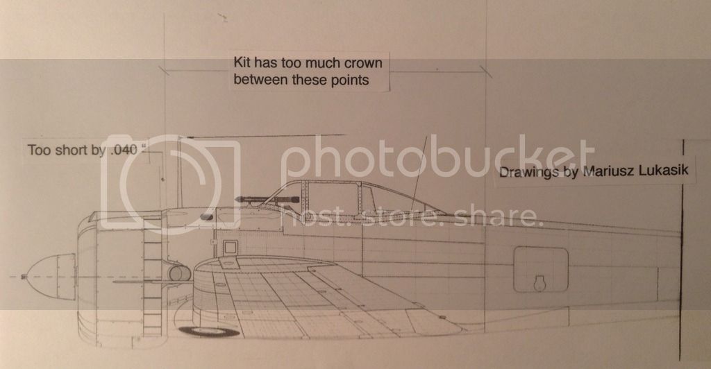
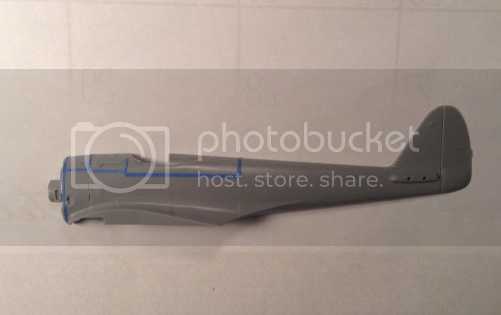
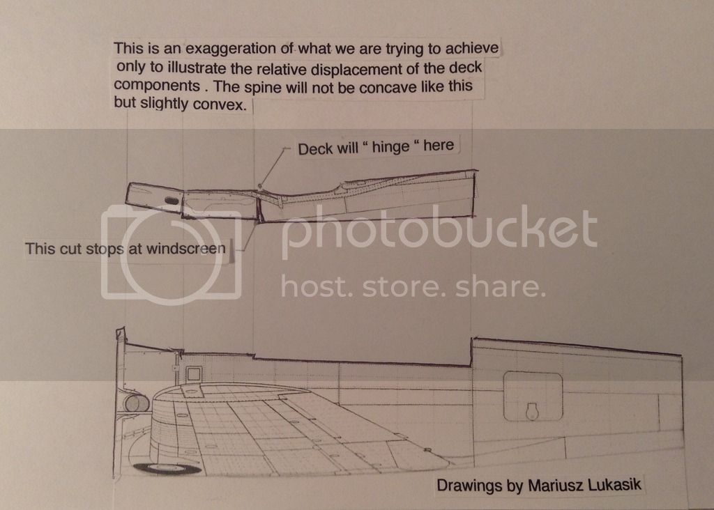
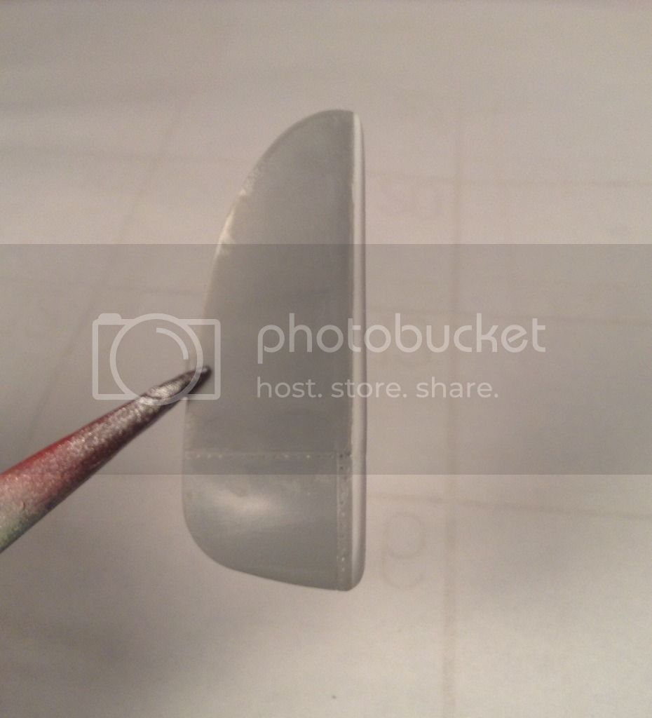
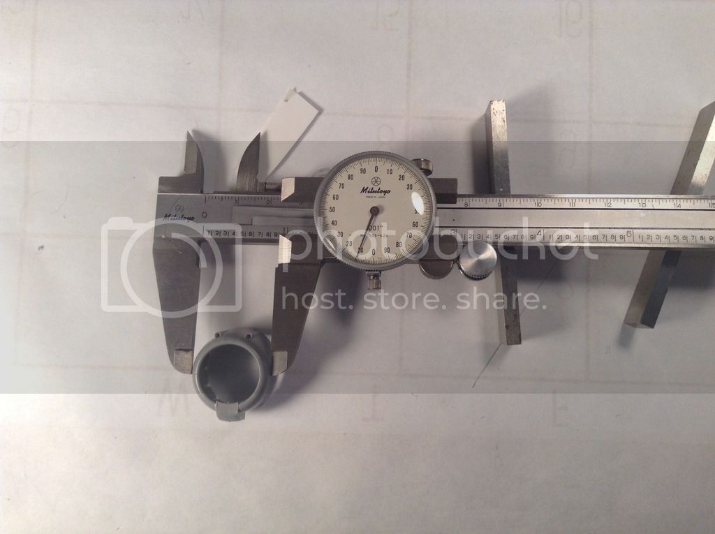
Some more progress to report but first I've discovered another shape issue to deal with. The Hasegawa cowl is cast in one piece including the cowl flaps. Likely as a concession to mold release considerations, the cowling has been made with too much pitch - especially so along the dorsal spine . This unfortunately adds to the " hogged" appearance of the fuselage . Photos and the Lukasik drawings show that the top edge of the cowling is only slightly crowned and nearly parallel to the engine / thrust centerline. This is difficult to discern and illustrate because the tubular blisters for the gun barrels obscure the top edge of the cowling at the center. Hopefully this photo of the cowl posed on the machinists' try square will give a hint of the issue.


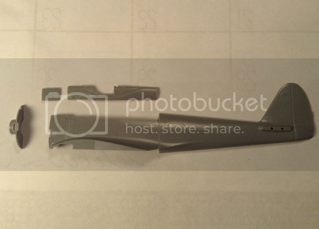
Possible solutions I am contemplating are cutting away the front cowl ring and replacing it with one from the FineMolds kit or turning one from scratch on the lathe - either way the sides of the cowling will have to be cut along panel lines to allow the sides to spread a bit.
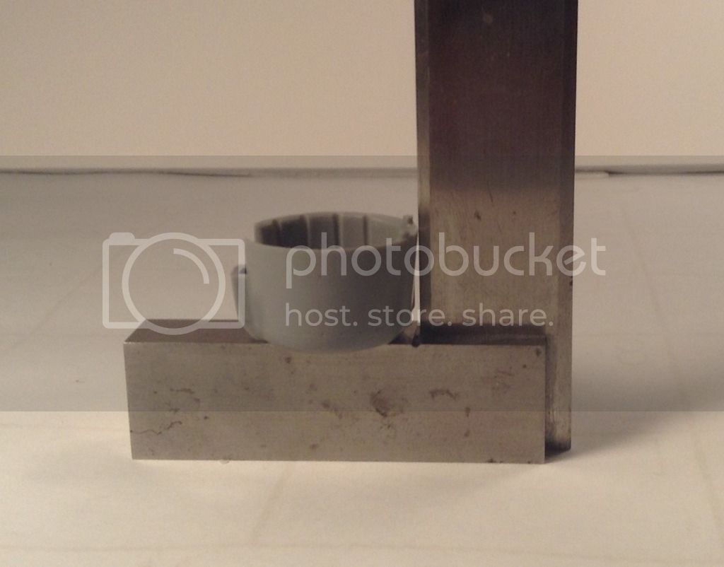
Here is the kit cowl ring diameter -


And the FineMolds diameter -


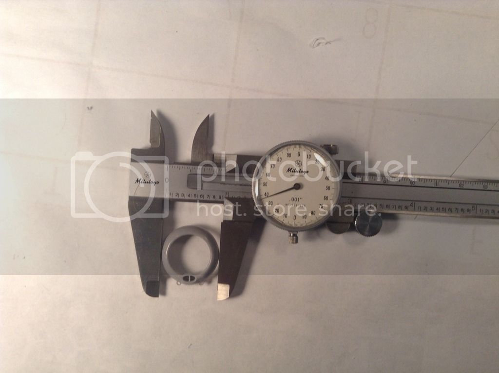
While the FineMolds ring is for the later Ki 43-II with the air inlet at the top it can be inverted with the air inlet cut away for the earlier Ki 43 - I bottom mounted unit. The larger diameter of the FineMolds unit may be enough to negate the pitch along the top edge- if it isn't then the answer may be to turn a new one from scratch.

Editorial Opinion Page

There are a few things that seem to be the subject of contention in this world of Japanese aviation - colors, accuracy of resources etc. I suppose the dearth of information on some aspects and its' attendant mystery are part of the appeal to me .This is probably a good time to reiterate my previous statement that I cannot vouch for the complete accuracy of the Lukasik drawings. I don't know to what extent they were researched - I do know they exhibit wonderful care in draftsmanship and the people involved obviously put in a great deal of work and , in keeping with the spirit of this effort , they look right to this trained eye. I'm all for accuracy and I applaud those who put in that kind of effort and I'm also grateful that resources such as this set of drawings are available. I hope this doesn't get misconstrued as a rant - only a testament of a sort- Thanks for listening !

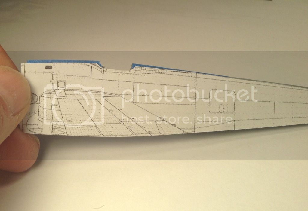
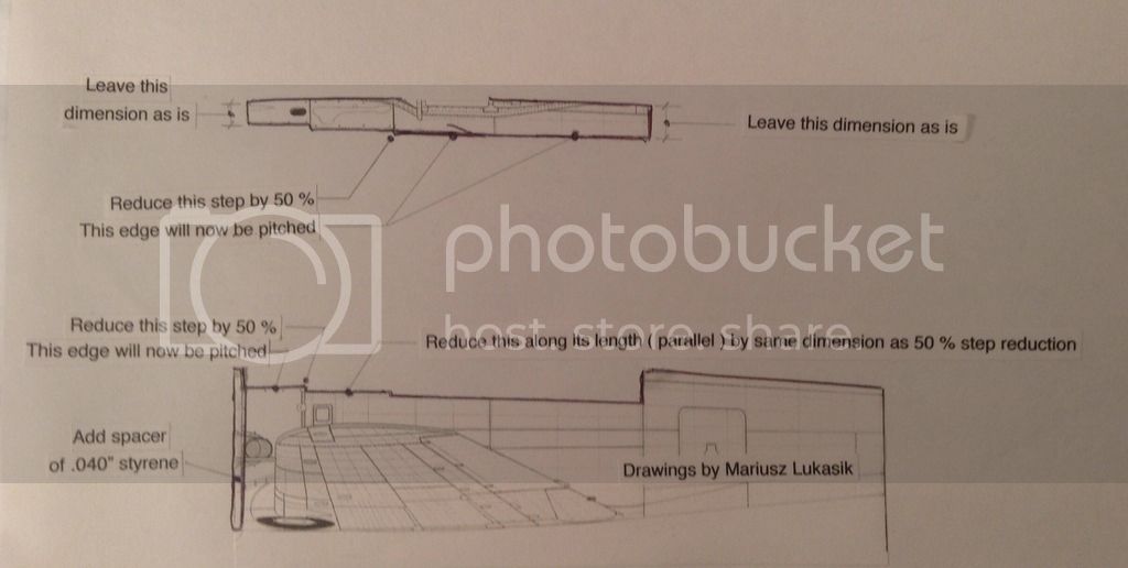
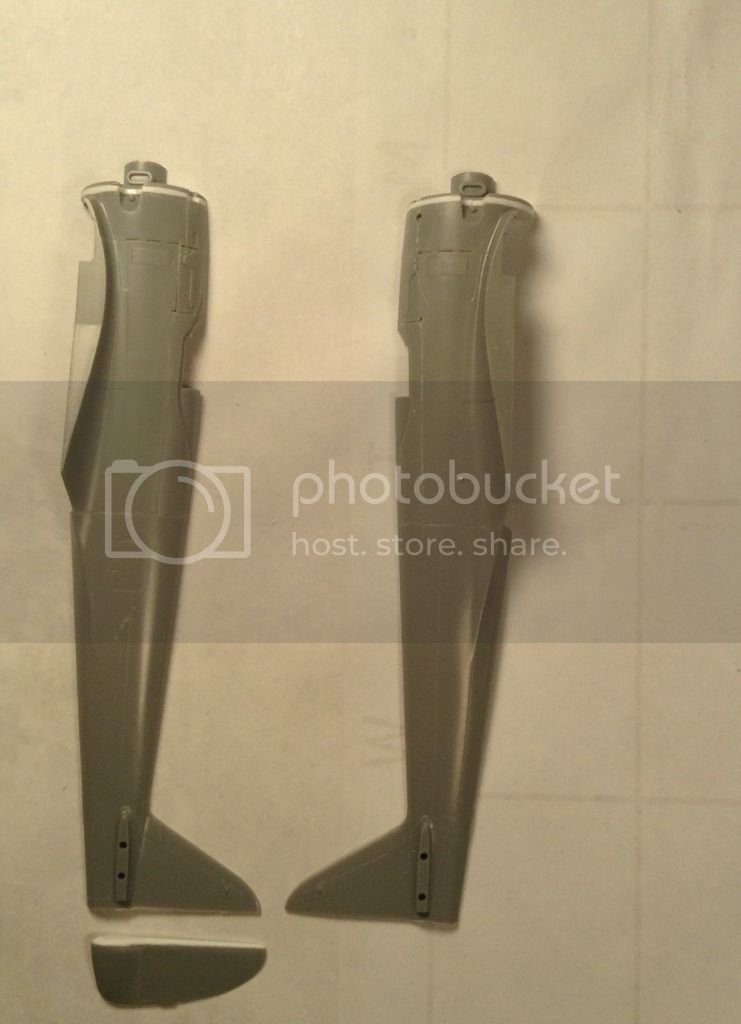
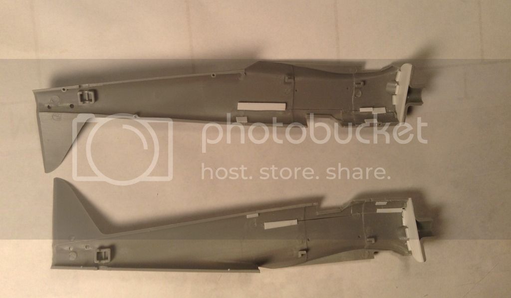
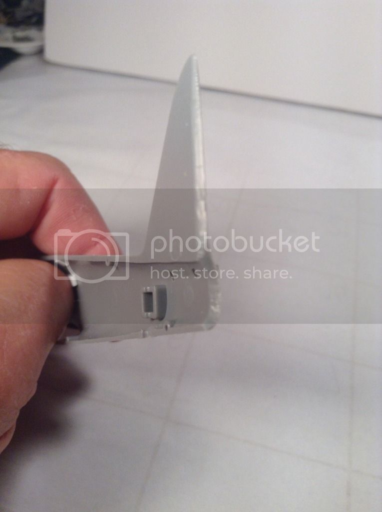
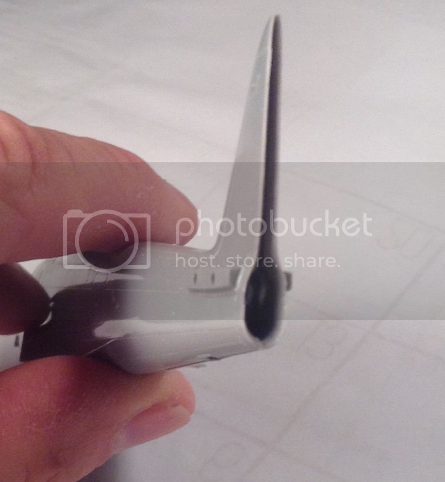
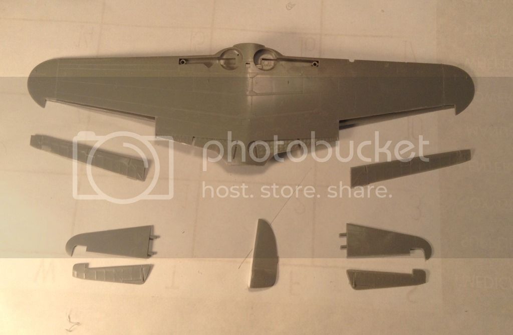
Moving on to the wing- the control surfaces have been cut away-


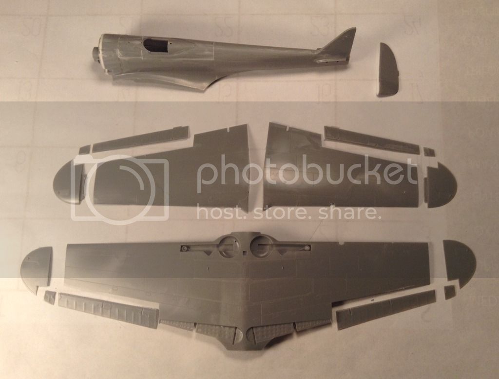
and the wing assembled and elevators cut away-


Next task will be the cowling issues.

Thanks for looking in-

Cheers and Happy Thanksgiving Day to all ! Richard
 _GOTOTOP