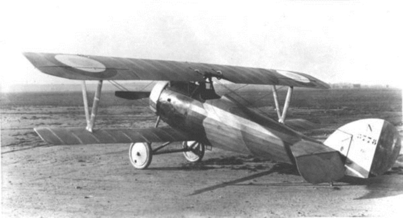
Aircraft in WWI often became obsolete, though having barely taken to the air. The fast pace of invention in aircraft design often led to nothing, and some ideas and developments became outmoded, which a year or two before had been considered as progressive and innovative. However, some design approaches, which might be considered simple in many respects, ensured not only great success for certain aircraft, but also a kind of rebirth in later types and variants. In the spring of 1917 the designer Gustav Delage developed the next new version of the fighter, the Nieuport 24. The fuselage gained a more rounded cross section in comparison with its predecessor and the wings were rounded at their tips. The horizontal and vertical tail surfaces were also very different from previous models, having a more rounded outline. A powerful 130-hp Le Rhône engine was installed in the plane. At this time the United States, which had just entered WWI, started organising their own Air Force from scratch, and they bought from the Allies all available types of aircraft to make up the complement of their air arm. France sold at least 140 Nieuport 24bis to the U.S., about a hundred Nieuport 24, and almost three hundred of the Nieuport 27. The Nieuport 24 types in British & French service saw combat, but mostly their fate until the end of the war limited to the training of future pilots. After the war many Nieuports were sold to private owners, while all other machines were sent to scrap. Apart from France and the U.S., the Nieuport 24, 24bis and 27 were used to a limited degree by the Royal Air Force of Great Britain. A few were sent to Russia where they survived the October Revolution of 1917, and appeared in the ranks of the White as well as the Red Army. Several machines were used by the Air Forces of Poland, Japan and Romania.
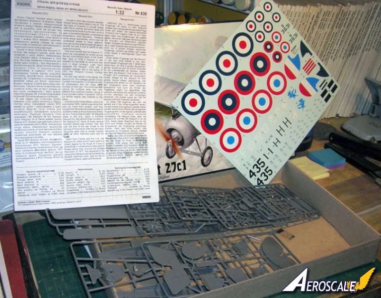
Kit Contents:
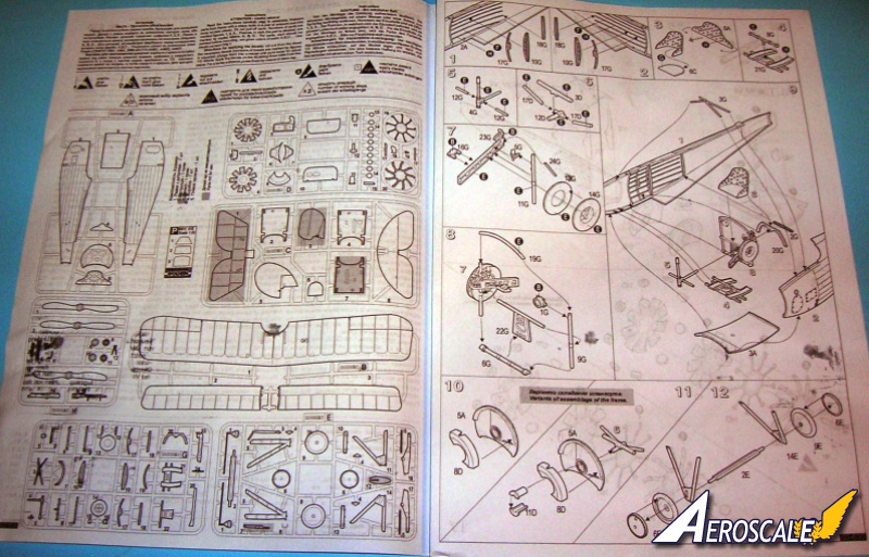
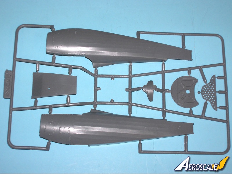
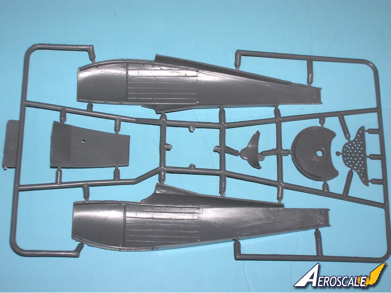
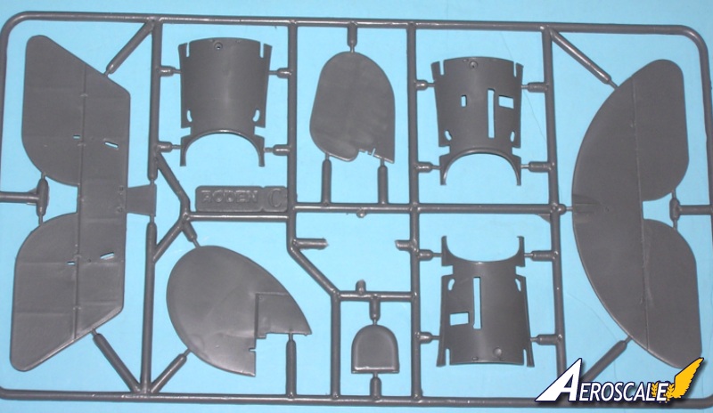
114 plastic pieces.
08 page instruction booklet.
06 decal profiles
This kit has an excellent interior for this scale. This would be a good place to predrill all strut and rigging holes.
The Build:
Note I did some preliminary fitting of Roden's Nieupot 24bis (same molding) in an Aeroscale review of kit #611. You might want to refer to it as well. See the additional images link below.
Step 1 & 2 Add short "X" sections of fine wire to the sides of the Fuselage Halves (1 & 2 A ) to represent internal rigging. The cockpit components ( 7, 9 17 A & 3, 11 B ) are attached to the lower wing ( 16 B ). You can manufacture a starter magneto, a hand pump to pressurize the fuel tank, fuel gauge, tachometer, oil pulsator, and finally a floor mounted compass. The kit does provide a full fitting for the mixture control support. It only has the portion of it closest to the pilot. A Tom's Modelworks French Interior detailing parts in 1:32 scale has many fine and unusual details not seen anywhere else that come at a reasonable cost.
Step 3.) The seat assembly (6 A & 6 C) is typical and should be represented as plywood. A seat cushion was usually added. At the unit level popular items of the day were pillows from a local house of ill-repute.
Step 4.) The foot tray & supports (21 G) are united with rudder bar (8 G).
Step 5.) The control column (4 G) is united with rod supports (12 G X 2).
Step 6.) Carburetor, air intakes and support assembly (3, 12 & 17 X 2 D) is to be used for detailing and in cases where there is no ammunition storage (as with a trainer) will be seen.
Step 7.) The throttle control assembly (5, 10, 16, 23 & 24 G) is united with the empty belt reel (13 & 14 G).
Step 8.) Next the fuselage interior structure (1, 6, 9, 19, & 22 G) is added to the reel for the empty machine gun belt. This is then to be located on the port side of the nose (1 or 2 A), just behind the exterior inspection hatch, and between the side wall and air mixture support bracket it will be visible.
Step 9.) The united fuselage halves (1 & 2 A) are joined and unites items from steps 3, 4 and 5. Erase all seams in the fuselage joints.
Step 10 & 11.) Next we unite the firewall (5 A) to the oil tank (8 D). The notch in the tank is for the spout and will be adjacent to the top dead center of the fuselage joints on the cowling (1 & 2 A). The shroud (11 D X 2) for the engine rear spindle is added and will then attach to the carburetor from step 6.
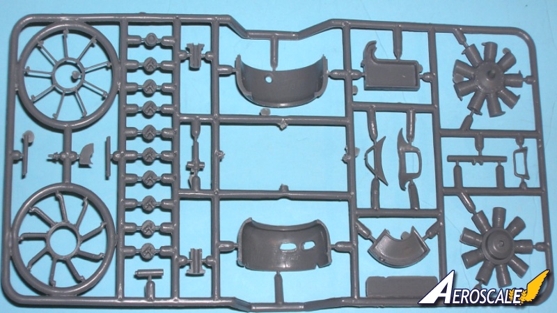
Step 12.) Lay the Axle (2 E) in the crotch of the landing gear (11 & 14 E) Next wrap upholstery thread around the front leg back to the rear leg and then forward again. Several rounds should do. This traps the axle and represents the bungee shock chords used on the original. The tires (6 X 2, 9 X 2 E) are last here.
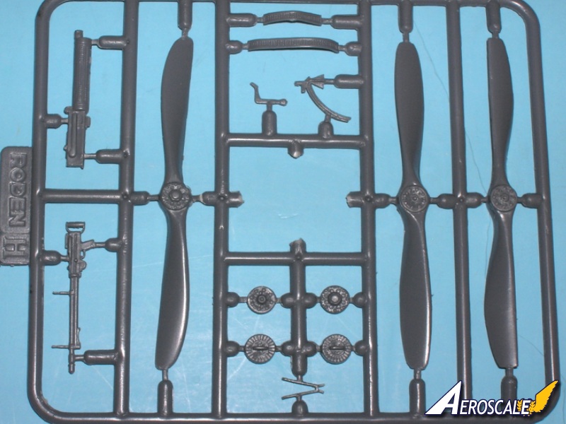
Step 13.) Vickers .303 machine gun assembly is a simple assembly (6 & 14 H).
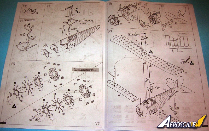
Step 14.) This shows the upper forward deck (7 C) inverted to attach the forward cockpit cross brace (7 G) and the ammunition box façade (5 & 18 D).
Step 15. If you want to do a trainer the Vickers .303 machine gun assembly from step 13 is deleted here. Note the empty belt chute (7 C) and ammo feed (4 H ) were all deleted. And for an unarmed build the upper decking (2 C) could be used instead. Indications are that most trainer aircraft never even had the external mountings installed at the factory. Note also the difference between the firewall assemblies. Add the front cabane struts (17 E X 2 ). These are excellent in their design.
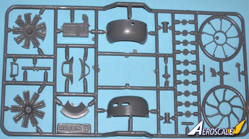
Step 16.) This sequence of building (seen from the back of the motor forward) the 120hp LeRhône is for the firewall as seen in step 11.
Step 17.) This sequence of building (seen from the back of the motor forward) the 120hp LeRhône is for the firewall as seen in step 10.
Note if you want to do a trainer version you need to use an 1:32 facsimilie of the 80hp LeRhône. This is not provided with this kit.
Step 18.) Here you add the engine assembly (from step 16 or 17).
Step 19.) Here you add cowling (9 & 10 D). Thin down the lower rear edge of the cowling for a scale thickness.
Step 20.) The tail control surfaces (8 C) and rudder (5 C) are a direct indicator of the designated type. You will find it important to drill a small hole adding a section fine wire to the rudder (5 C) and its joint surface at the stern post of the fuselage assembly.
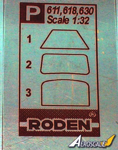
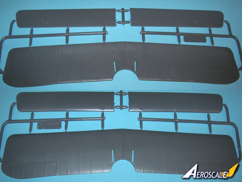
Step 21.) The lower wings (2 & 3 B) need better attachments and I suggest brass rods inserted into drilled holes where the kit attachments were. I suggest adding the interplane struts (5 E X 2) to the top wing (1 B) first and let fully set. The rear cabanes (10 & 13 E) and windscreen frame (7 D) can be added next. The aileron actuation rods and bell cranks (1 E X 2) should be set to compliment any attitude of the ailerons you have selected. When thoroughly dry begin the rigging process. The top wing mounted Lewis gun (7, 11, 12 & 15 H) is a simple affair and applies to profiles I, III & VI. Profile IV is a trainer and should be unarmed.
Step 22 mismarked 20.) I will add the landing gear from step 12 and the un-shrouded tail skid (3 E). Lastly add the propeller at this point. The French propellers were built up in the conventional way by laminations. For Nieuport & Spad fighters finishing included a solid uniform coat of red-brown shellac in most cases. Fortunately the Nieuport fighters are a good first kit for attempts at rigging a WWI aircraft. Remember always to drill the smallest hole to anchor your rigging material. The more lines to anchor enlarge the hole. Wait until the anchored lines have dried thoroughly. Pass the other ends through their next hole and hold them tight by clipping a spring type clothes pin to the lines end. Touch the smallest drop of superglue (cyanoacrylate) to the area and again wait until dry. Only a sharp razor knife should be applied to the loose ends of the strands. I like to fill any remaining holes with resin dust, wood dust (when I cut my own laminated propellers) or even baking soda to holes with the glue drops already in them. This filler takes only a small amount and dries almost instantaneously with thin consistency superglue (cyanoacrylate.) Complete any unfinished rigging at this time.
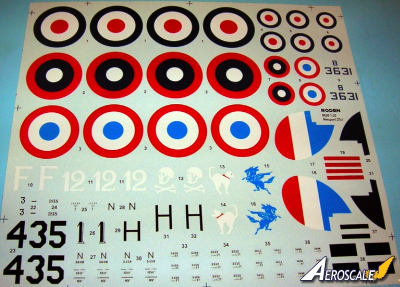
Kit Decals:
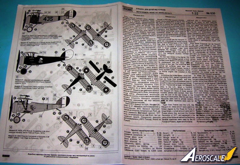
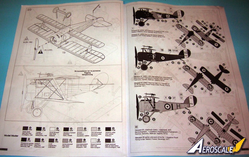
1.Nieuport 27, N5690 flown by Sgt. Marcel Gasser of Escadrille N.87 Aviation Militaire. France, Spring 1918.
2.Nieuport 27, B3631 flown by Capt. H. J. Hamilton of No.29 Squadron Royal Flying Corps. Proven, France, December 1917.
3.Nieuport 27,(serial unknown) of the No. 1 Squadron Royal Flying Corps. Baileul, France, December 1917.
4.Nieuport 27, N8660, #435, 3 AIC, Issoudun, France, May 15 to August 1918.
Note: the 22nd Aero was not at Issoudon 3rd AIC. It was a frontline unit. Lt. Swaab was undergoing training at Issoudons 3rd AIC and not yet assigned to the 22nd Aero. The large numbers like 435″ were on their trainers that the students flew regularly.
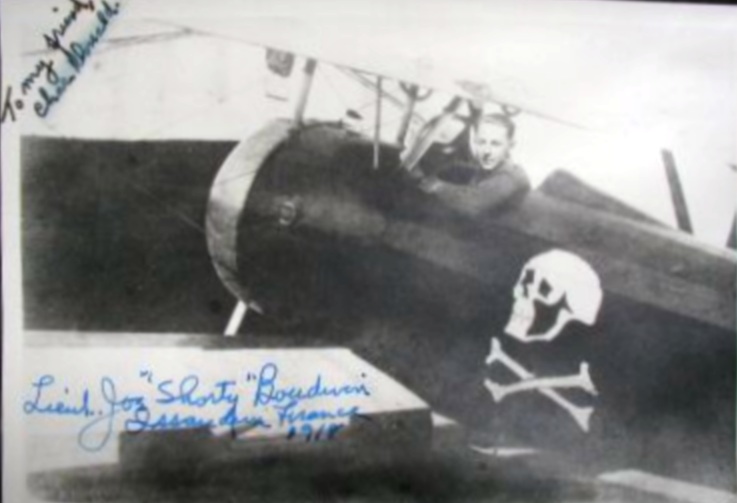
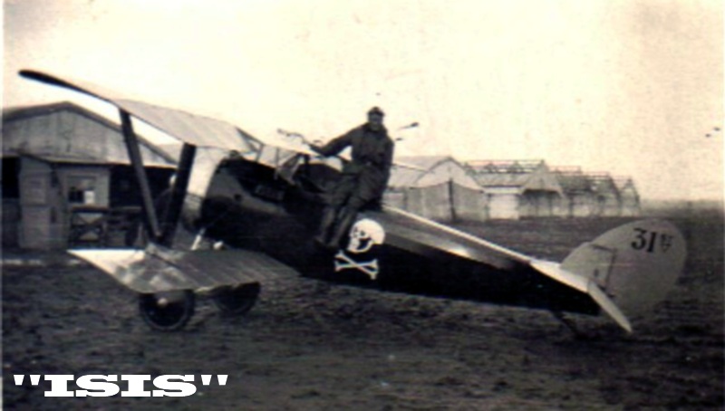
5.Nieuport 27, 31st Aero Aero Training Squadron at Field Five 3rd AIC.Issoudon, France, mid-1918.
The skull-n-bones was the insignia of the 31st Aero at Issoudon, but was only on the training a/c assigned to the cadre instructors. (The students took their graduation photos in these machines.)
6.Nieuport 27, N5532 flown by Commander of Escadrille N.99 Aviation Militaire Capt. Roger de Richemont, 1917.
Reference:
Billy Bones - An Accounting of the 31st Aero sqdn by S.T. Lawson, Cross & Cockade Intl. Vol. 37 #2 2006.
Issoudon and the 3rd AIC AEF.Cross & Cockade Intl. Vol. 37 #2 2006.
List of Aircraft Designations (French) submitted by P. Grosz, Cross & Cockade USA Vol.25, #2, Pp.112-115, 1984.
Nieuport Aces By N. Franks, Osprey, Aircraft of the Aces #33, 2000.
Nieuport Fighters of WWI by J.M.Bruce, Osprey, Vintage Warbirds #10, 1993.
Nieuport Fighters Vol 1 by R. Rimell, Albatros Pub. 1993. Nieuport Fighters Vol 2 by R. Rimell, Albatros Pub. 1994.
Nieuport Vee Strutters by S. Nelsen, Cross & Cockade USA, Vol.7, #3,Pp.237-253. 1966.
Nieuport Vee Str. Errata & Addenda, Cross & Cockade USA Vol.12,#2, Pp.189-190. 1971.
Summary of American training at Issoudon:
(From the Manuscript Billy Bones - An Accounting of the 31st Aero Sqdn.) If you had found yourself in Issoudon, France at the Third Aviation Instruction Center (3rd A.I.C.) with the American Air Service as a pilot trainee in 1918, it would be a matter of course that you come to Field Five. Landings, Spirals and Acrobatics were the daily meat here. Considered to be the advanced training phase Field Five had a wicked reputation for being the field of graves to many would-be knights of the air. The price of training 3,111 men at Issoudon was $27,045,395.53 in 1918 alone. This created an average cost per man of $8,693.47. If the war had continued through 1919 the projected total cost of training was expected to rise to about $40,000,000.00. At the Third Aviation Instruction Center there were assigned as cadre 1,165 officers and 4,860 enlisted men to keep the training schedules on target and aircraft flying for the operations of its eventual 14 airfields training both pilots and observers.
At the headquarters of the American Expeditionary Forces in Paris it was with typical military consideration that the Projects Department selected the worst possible land for use as a training area under the most grievous weather conditions. The hardships of military life during war are compounded by the rear echelon types that make decisions from their comfortable offices. Farmland was set aside for the use of the American Air Service training. Almost over-night barracks and hangars went up, roads were cut and graded and trucks traveled to disbursement points to pick up water, supplies, cadets and coffins in a daily routine. Much like a casual view of an ant farm, each and every movement of the hive was meant to prepare young men to face the duty of war in the air.
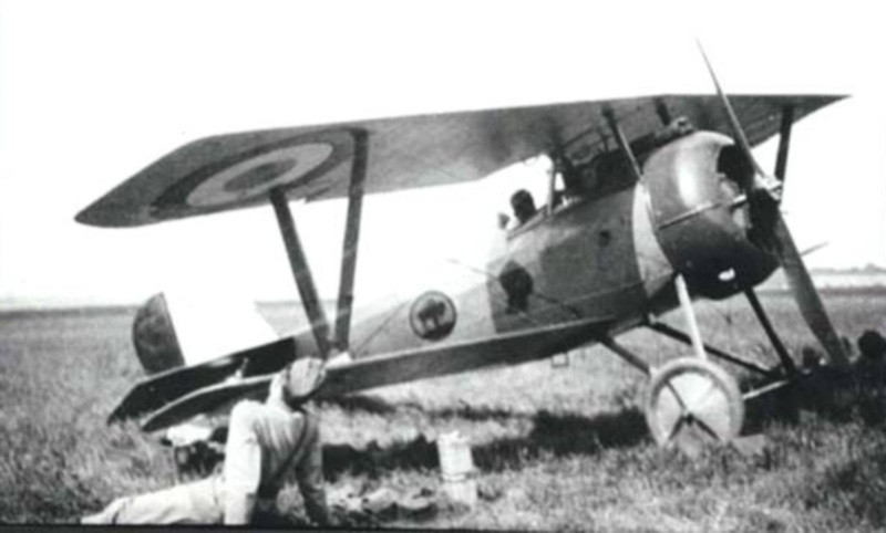
Each Field had its academic and operational specialties. Depending on when a student passed through the 3rd A.I.C. some classes were moved from one Field to another as it expanded and grew. Field One taught Taxing in clipped wing Morane Saulnier Parasol (Penguins) types. This was needed to teach the novice about controlling the machine on the ground first. Field Two taught Dual Control Operations on Nieuport 10 and 12 types (23 meter.) This involved the student being watched over by an instructor. If there was a problem the instructor could take over control of the machine. Field Three students flew Cross-Country flights. These flights were to teach the student how to recognize familiar terrain features and be able to orientate him self by using landmarks. Field Four familiarized students with the Nieuport 21 (18 meter types) and later on, the Nieuport 24 (15 meter types.) The types chosen for training purposes included Nieuport 21, 21 bis, 24 and 24 bis. Field Five as discussed earlier taught Full Power Landings, Spirals and Aerial Acrobatics. Most of these instructions were done on the ground with the student in the cockpit and the French instructors standing on a ladder beside the aircraft counting out the steps in a given maneuver , Un. Deux, Trois, Quatre. Then the maneuver was attempted inflight. At Field Six students learned to Land an aircraft Dead-stick (motor power off.) Field Seven was used for Formation Flying. Field Eight was where the students were transitioned to newer and armed fighters like Spad, Sopwith, SE 5a and late Nieuport types. Students were given sealed orders and told to go up and hunt a fellow student, theenemy in a certain area with an aircraft that would be camera gun equipped.. Field Nine was developed to include a gunnery range, so when the French school at Cazaux was full students could carry on their training. Some veterans have said that they believed that the graves were at Field Thirteen. The fact appears that there were some graves at all of the operational fields. Fields 10 -14 handled Bomber and Observers operations training. Cadre and students are quoted as saying that ...there was a funeral at the 3rd A.I.C everyday but Monday and the day after it rained.
More pilots and students were killed on the Nieuport 21 (18 meter) type than any other according to former Lt. Temple N. Joyce. Who not only graduated from the 3rd A.I.C. in Feb. 1918. but returned in mid 1918 to become its Chief Test Pilot and Accident Investigator. The Nieuport 21, 18 meter (with 80 hp LeRhône rotary)was chosen to be the first trainer for the Americans. It was essentially a Nieuport 17 C.1 without armament. Since it wasnt intended to carry any armament or ammunition it was not necessary to have a Nieuport 17 motor (110-120 hp LeRhône rotary) to attain a similar performance for students. The bis suffix was denoting a variation that might include altered wing, tail or fuselage surfaces. These variations were often incorporated in subsequent production types as standard features. The Nieuport 21 bis included a fully rounded or faired fuselage and the Clerget 110hp rotary. The Nieuport 24 had the similar layout but included alterations to wings ,15 meters in area, tail and a fuselage rounded out using stringers from cockpit to tail. The Nieuport 24 bis kept the altered fuselage and wings but reverted back to the Nieuport 17 and 21 vertical and horizontal tail surfaces. The Nieuport 27 bis was essentially a Nieuport 24 bis with a split axle like those found on Sopwith fighter aircraft. It has been noted that at least some of the instructors or Commanders aircraft often kept the original/ higher horsepower motors with 110 - 120hp LeRhône 9J, Clerget 9Z or 9B types. When a class of students finished their courses at Field Five, they were transferred to Field Seven. If the class at Field Seven is still finishing your class would have stand-by waiting at Field Five, Since there was very limited barrack space this could hold up the class that was due to come to Field Five. The old Hurry up and wait gameat its finest. The only Field that never seemed to experience this concern was Field Thirteen. As stated earlier each of the existing Fields seemed to have its share of graves by Summer 1918. There is no indication that after Field Thirteen was established that any existing graves were moved from the other Fields to be re-interned there.
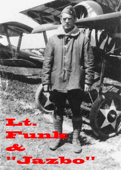
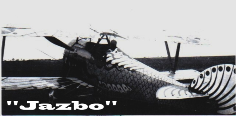
In the end it was all erased. The land was returned to the farmers. The buildings and hangars were torn down. The graves of the fallen instructors and students were moved to perpetual cemeteries. In 1962 a former Instructor at Issoudon, Mr. Keeling Pulliam of Field Four whos various Nieuport fighters were painted like 1.American Eagle & 2. A carnivorous Flying Fish ( not the ship called The Jazbo. ) said when he visited the original site he could find nothing to prove that there was ever a training center. That is until he ventured into a stand of trees where he found the stone pillar that had once served as part of the entrance to the Main Fields (One -Two & Three.) These were located at the hub of the Third Aviation Instruction Centers operations in 1918.
Please remember, when contacting retailers or manufacturers, to mention that you saw their products highlighted here - on AEROSCALE
SUMMARY
Highs: Great surfaces and kit details. Both forward cabane struts and lower internal structure in one piece. General fit is good and the parts measure out well against modern plan views.Lows: The fabric bindings on the interplane Veestruts need to be reduced in thickness. The engine fits only the armed fighter and the instructor's version of the trainer.Verdict: Excellent kit with care will yield a fine build.
Our Thanks to Roden! This item was provided by them for the purpose of having it reviewed on this KitMaker Network site. If you would like your kit, book, or product reviewed, please contact us.
About Stephen T. Lawson (JackFlash) FROM: COLORADO, UNITED STATES
I was building Off topic jet age kits at the age of 7. I remember building my first WWI kit way back in 1964-5 at the age of 8-9. Hundreds of 1/72 scale Revell and Airfix kits later my eyes started to change and I wanted to do more detail. With the advent of DML / Dragon and Eduard I sold off my ...


Comments