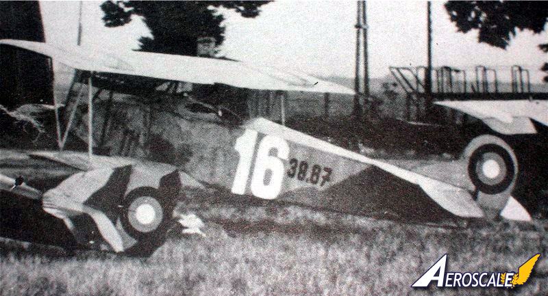
At the end of the war the allies wanted every example of the Fokker D.VII they could lay their hands on. The plants building them were the parent company of Fokker at Schwerin, also under license by OAW (East German Albatros Works)at Schneidemuhl, Albatros Works at Johannistahl and Ungarische Allgemeine Machinenfabrik A G (MÁG). Since the Schwerin built Fokker D.VII fighters arrived at MAG too late to be taken into the Luftfarhttruppe inventory - that is they did not receive the standard Austro-Hungarian numerical serial designation. It appears that the Hungarians simply designated the Schwerin built Fokker D.VII fighters with the existing works numbers. Appearing in Hungarian squadron records was D.VII 3861, 3863, etc. An intriguing question is: why was designation 38.67 (based on the Austro-Hungarian system) applied? It should be noted that the true serial 38.67 wa assigned to Aviatik D.I 38.67, which was built by the parent company and shipped to the front on 20 July 1918. Consequently there is no question that the Fokker D.VII 38.67 serial number was based on its works number and not an official Austro-Hungarian military serial number.
The Osterreichische Ungarische Flugzeugfabrik Aviatik G.m.b.H. was awarded a production contract for 150 Fokker D.VII fighters. But when the war ended only the most preliminary work had been done. None were built and on 31 October 1918, ( with cessation of hostilities imminent ) the production contract was cancelled.
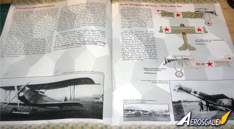
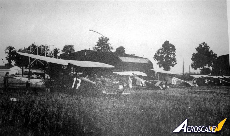
The Ungarische Allgemeine Machinenfabrik A G or (MÁG) on the other hand had their production of the 150 Fokker D.VII fighters well underway. Delivery was scheduled to begin in December 1918. These machines were designated as Fokker D.VII (MAG) series 93 and aircraft 93.01, 93.02, 93.03, 93.07, 93.08, 93.16 & 93.18 have been recorded in Humgarian archives and photographs.
Kit History
Arguably the leader today in WWI aviation models Eduard presented their first version of the 1/48 Fokker D.VII kit in 2005 in their Limited Edition series. In 2006 their 1/48 Fokker D.VII mold was released in the Dual Combo line and was seen later in their Royal line. Now the Dual Combo Limited Edition series is a surprise. As it costs about thirty US dollars more for two complete kits compared to the normal Dual Combo series. I will refer to plastic parts as PP and photoetch as PE.
They say. . .
It was on another black and stormy night in the Czech Republic, lightning again ripped the skies near castle Eduard. Deep in the bowels of the old south tower, the ruddy skinned trolls work furiously packaging their masters new creations. A twisted set of boney hands nail the lids down on the deeply packed wooden oblong crates. In the eerie half light teams of tall draft horses hitched to heavy hay wagons shy and jump from the lightning flashes as if standing before the glue factory doors of eternity. As each wagon is filled to overflowing and its shrink wrapped cargo tallied for the final time the goblin like drivers crack their long bull whips and the team disappear into the black void of night. Then, a thin, pale, tuxedo clad figure sweeps his high necked and flowing cape steps up to the huge oak doors and peers into the rain soaked night. One of the overseer trolls reaches with a twisted claw for the volume knob on the 1923 Philco radio and turns up the blasts of Edgar Winters Frankenstein. Moments later, suddenly the tuxedo clad figure cries out, That will do troll ...that will do!!! Thus another scale wonder is borne to the worlds hobby shelves.
Box Contents
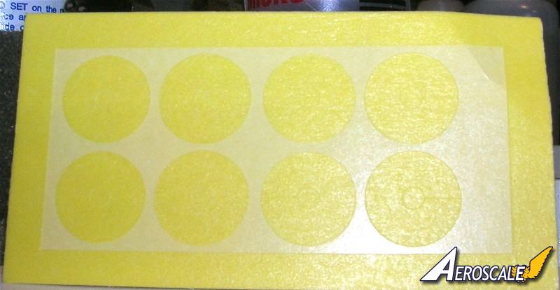
Two complete kits with photo-etched accessories and express mask.
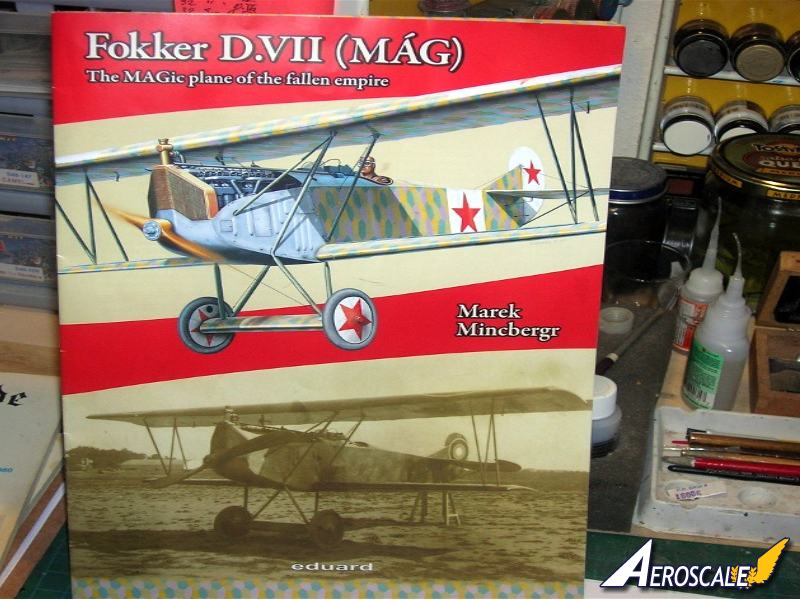
16 page full color publication on history and camouflage of the Fokker D.VII(MÁG).
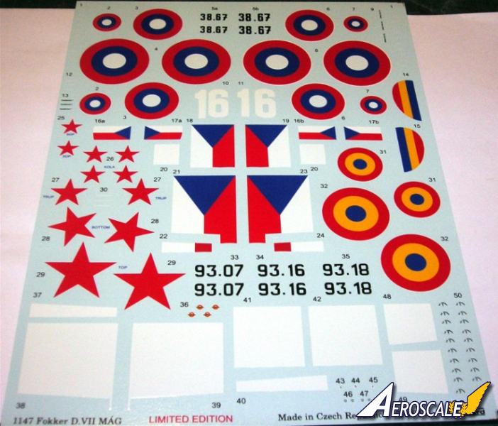
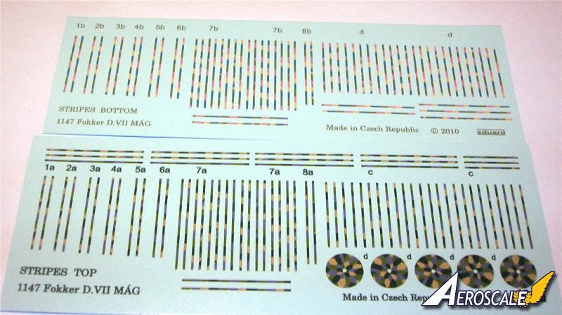
Decals and description for 11 specific markings (7 Czechoslovak, 2 Hungarian and 2 Romanian).
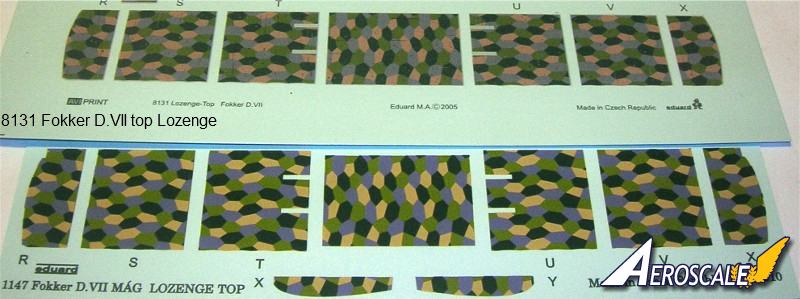
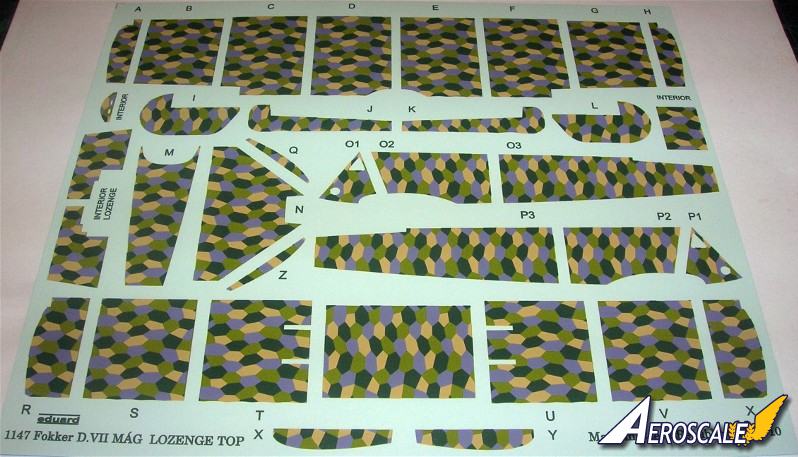
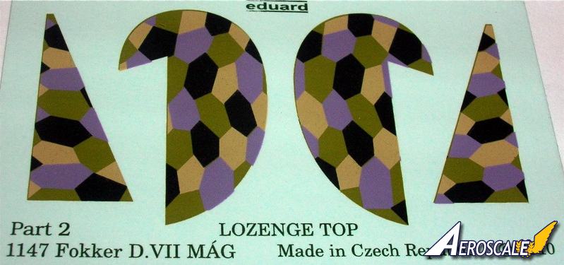
3 variants of camouflage - Lozenge pattern (as huge decal), three-color early Czechoslovak camo and pure canvas.
Nicely cast and PE detailed 225hp Austro-Daimler engine.
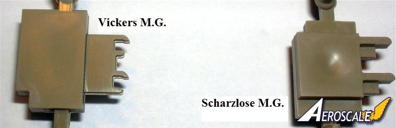
Late model Vickers and Schwazlose machine guns.
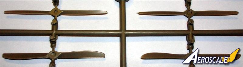
3 variants of propellers and 2 variants of landing gear
The kit allows displays with open or closed engine covers.
The Build
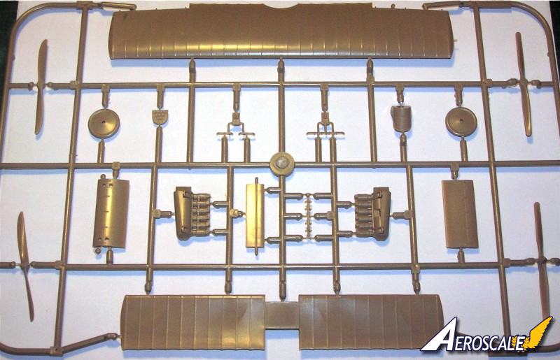
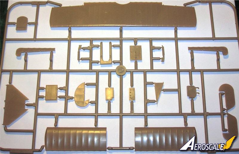
Pages 1. Text and parts map. Express masks dealing with the colour profiles are limited to colour demarcations of the wheel covers. Also there are the legend, parts map and colour references. Before beginning, wash your kit plastic in mild dish soap & water, dry completely, then pre-drill and clean up all rigging and strut locator holes.
Page 2. Next the cockpit flooring (PP A 7 ) The rudder bar ( PP C 33 ) inserted through the flooring (PP A 7) and needs a vertical bar attached centrally. Like the DML Fokker Dr.I set up, this vertical column should angle back and up behind the ammunition box (PP A 16.) On the control column (PP C 27) note the throttle lever has one handle We also have photos where two are present. Check your references. Set the rudder bar (PP C 33 ) to the desired position to compliment the attitude you have chosen for the rudder. Scratchbuild an aileron control V for cables and attach the V at the front end of the lower control bar molded to the cockpit flooring (PP A 7) . Also add the compass ( PP C 14 & PE 10.) Also here, add bent and shaped brass wire for the throttle and the cables for the Spandau machine guns. Later you will have to add all the control rigging material to the elevator control column(PP C 27 ) and the rudder bar column (PP C 33 ) when the cockpit rear bulkhead / screen (PP A 11) is added. Some of these cables should to go through holes that you need to cut in the rear bulkhead / screen (PP A 11 .) Check your references for the various cables and wiring that are attached to these units.
The seat (PP B 12 & 15 ) sets into its supports that are to be built up in a box frame ( C 17, 18 & 32) and attached to the rear cockpit bulkhead / screen (PP A 11.) I trimmed down the inside surfaces of the seat ( PP B 12.) ( The seat was known to be covered in fabric that was held by attaching it to eyelets in the seat backs outer rim.) I also deleted the seat cushion (B 15.) As parachutes had come into use the seat was made deeper to accommodate the chute pack as a cushion. There was not any tucked leather or buttons on the chute pack surface. In the cockpit rear bulkhead / screen (PP A 11) note there needs to be holes for the rudder control cables to pass through. Next remember the rudder control cables that will be added between the bar and the stirrups will need to go through these holes. Whatever the fuselage covering use the same covering on the bulkhead/screen (PP A 11.) In this case of 4 or 5 colour lozenge. The pilots shoulder harness straps (PE 1) are attached to the seat framing (PP C 18)behind the seat (PP B 12.) Next the location for the fuel pressure hand pump ( PP C 10.) You my want to add a half loop of painted brass wire to simulate the air hose leading toward the front of the cockpit strapped to the framework.
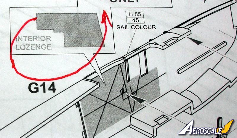
First of all choose which fuselage variations you are going to build. You can replace the molded cockpit structure in the fuselage halves (PP G 6 & 14, 23 ) with painted brass rod sections or after you apply the interior surface lozenge decals and they thoroughly set, dry brush the details with a light grey or grey-green to bring out the airframe skeleton. Note that the factory printed lozenge pattern fabric used on the Fokker D.VII showed through the interior of the cockpit sides in reverse in lighter shades. For the exterior the kit supplied four colour lozenge colours are way too light. But in an attempt to help the modeler work with what comes out of the box I will offer a fix. A wash coating of translucent dark brown and / or black tends to help greatly. I have to admit that this is one of their better efforts to provide the lozenge camouflage compared to what they have offered in the past. I prefer the Microsculpt lozenge decals instead of the kit provided items. Their clear carrier film on the lozenge decals allows them to be easily reversed. Just apply a little decal Sol & Set.
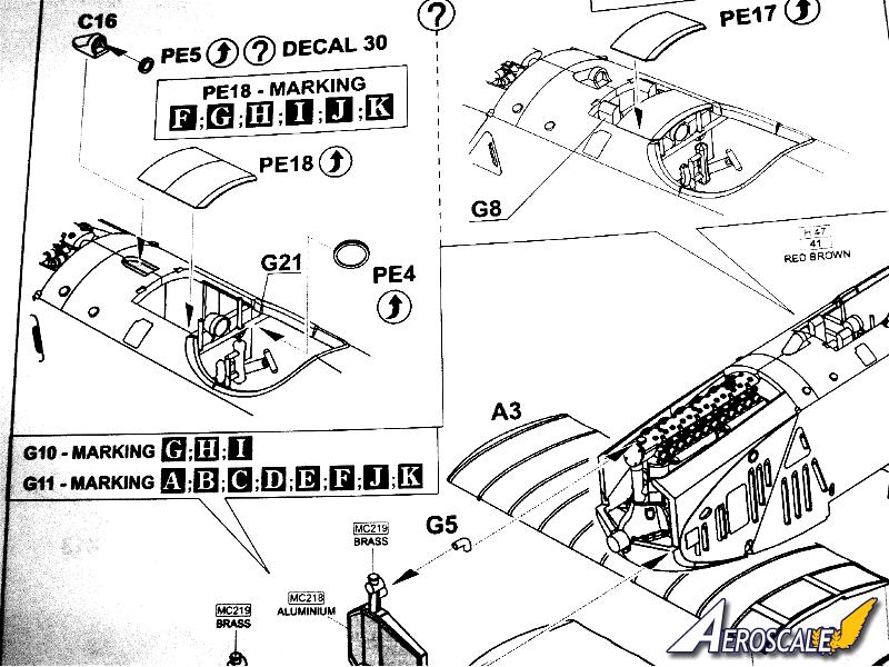
Concerning the instrument panel (PP A 14 or PE 14 & 15 ), I will usually paint Fokker company instrument panels black and give MAG types a varnished wood look. Eduard has pre-painted their photoetch (PE 2 & 3) a wood colour. They have also given the modeler a great set of photoetch instrument panel parts and fuel gauges for two complete kits. I also added a hand crank spare part as a handle to magneto and flip levers (PE 25 X 4) to fuel and air controls. I also add the tachometer (PE 6)or decal #28 dial face to the machine gun rear brace (PP G 21 or 22). In mid-summer the items upper cowlings would be removed during flight operations. This would be typical of a machine in mid to late(June - Nov.)1918.
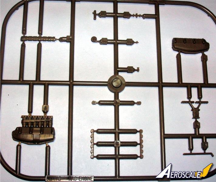
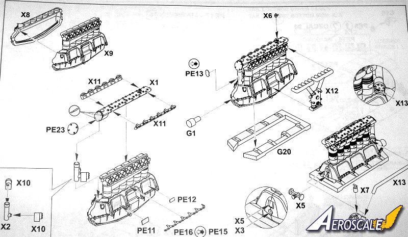
Page 3. The Engine (PP X 1-3, 5-9, 10 X 2, 11 X 2, 12, 13)&(PP G 1 & 20)& (PE 11-13, 16 X 2, 23) is supposed to represent a late model 225hp Austro-Daimler inline six cylinder type.
There is no main fuel, reserve fuel & oil tank assembly. Then we see the method of attachment of the engine and the typical Eduard bearing shelf to the raised edges within the engine compartment. Note Eduard has provided for a vertical installation of the Firewall (PP A 8.) This is incorrect and should have an incline at the top toward the engine compartment. To do it right you will have to erase the forward most, lower locating ridges. Then line the rear face of the firewall up on the outside of the forward most, upper locating ridges. The fuselage havlves (PP G 6 & 14 )out of the box the cowling opening for the engine cylinders is larger and easier to see the firewall is too far back.
Page 4. Here we assemble the lower wing parts (PP A 2 & 3, B 1.) One could actually insert spars held in place with double sided tape or glued in place. This type of wing assembly is great for the modeler who wants to simulate damage. By thinning down the inner surfaces, internal structure is easy to replicate. Also, before putting the lower wing together sand the vertical edge of the lower wing at the roots of all three lower wing components (PP A 2 & 3, B 1.) The unmodified fit between the lower wing an fuselage is tight and cause anhedral just like the Roden kit. This fix will eliminate the fit problem. Do Not narrow the whole fuselage by taking away from the center union area.
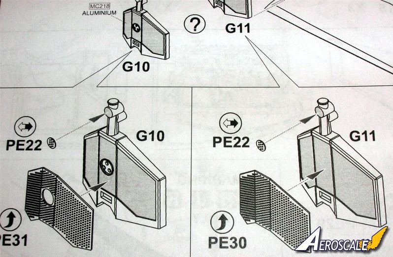
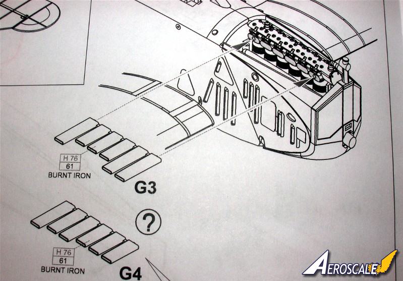
The fuel gauge (PP C 16) can have a decal(#30) or a metal gauge face (PE 5.) Note that the large ammunition round counter gauges (PE 4 X 2) are located on both sides of the machine gun rear brace (PP G 12 ) not just one. The radiators (PP G 10 or 11) have plain internal faces and no shutter assembly. Eduard chose completely enclosed cowling types and thusly no detail was added. The early and mid production versions were known to operate with upper cowling panels removed during the hot summer months. Check your references. If you decide to open up this area, you may need to alter the rear face of the radiator (PP G 10 or 11) before you attach it. By scribing some crisscross lines in the rear face of the radiator you create a better simulation. After painting or decal applications, assemble the horizontal stabilizer (PP A 10.) Eduard has given the modeler an easy way to deal with the undersurface fuselage fabric seam (PP C 21.) A first for WWI aviation modelers. The altimeter gauge ( PE 5 ) is optional as some pilots used wrist watch sized types. Next the horizontal tail unit stabilizer struts (PP C 20 X 2 ) and the tail skid (PP C 12.) I did replace this item with a modified brass rod for strength. It looks like Eduard originally forgot to add two control horns (PP C 11 X 2) to this image. For the exhausts (PP G 3 & 4 ) Next, werke numbers, factory serials and rudder cross were applied.
Page 5. The instructions take this time to discuss the application of its lozenge. For me it seems that this should have taken place two pages back before assembling the major sub-assemblies. See the rear cover of the profile monograph for more. The four plates are hinged panels (PE 19 X 4) to access the lower wing spar attachment for the fuselage. Note these should have the triangular plates (PE 33) on the fuselage, located immediately above the hinged access plates (PE 19 X 4.)
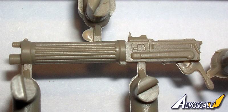
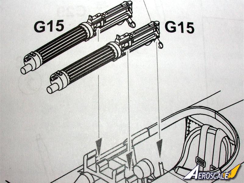
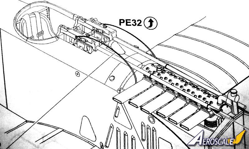
The kit Schwarzlose and Vickers machine guns (PP G 2 X2 & 15 X 2 ) are entirely plastic. The completed Schwarzlose machine guns should be painted in semi gloss black. The Vickers should be natural metal. Some highlighting in gun metal colouring maybe appropriate. You have the option to install smaller round counters (PE 6 X 2 ) directly to the gun breeches. On the previous page larger versions were discussed.
Page 6. The Eduard top wing assembly (PP A 1, 4, 9 B 2) does not have the mold casting problem found in most of the DML / Dragon kits. Next comes the rudder (PP A 12) and stabilizer fin (PP A 15 ) and control horns ( PP C 3 X 2.) On the original aircraft these items were covered in normal fabric (either plain or lozenge depending on the batch). As this begins to dry set the attitude of the elevators (PP A 17) that you wish to reflect.
By this time I have painted and added decals to all completed wing surfaces and they are thoroughly dry. As mentioned earlier this type of wing assembly is great for the modeler who wants to simulate damage. By thinning down the inner surfaces, portions of internal structure is easy to replicate. For those of you with AMS - a strip of 20 thou strip could be added between the cabane attachment points out to the leading edge mating surfaces of the top wing. It helps the Eduard wing match the wing thickness shown in Anthology 3. Otherwise the wing will be too thin seen from the front. Even with this easy mod, it's still not as deep as the Roden wing, but that may item be on the too thick side. Add the control horns (PP C 11 X 2) next. More is discussed here about the Lozenge placement. See the rear cover of the profile monograph for more.
To bring the fuselage and top wing assemblies together I use childrens Lego blocks. to form a jig to keep everything level and square. Then add the interplane (PP C 5 X 2 ) struts first, then the cabane (PP C 9, 15 30 & 31) struts. The anemometer ( PP C 29, PE 9) is an air speed indicator. The plastic struts are commendably thin and clean up quite nicely. My own opinion is that metal etched or white metal load-bearing struts or supports gives a build a much greater longevity. Continue the cabane strut (PP C 9, 15 30 & 31) attachment details. On the Schwerin built machines the grab handles (PP C 8) do splay out about 30 degrees from the fuselage.
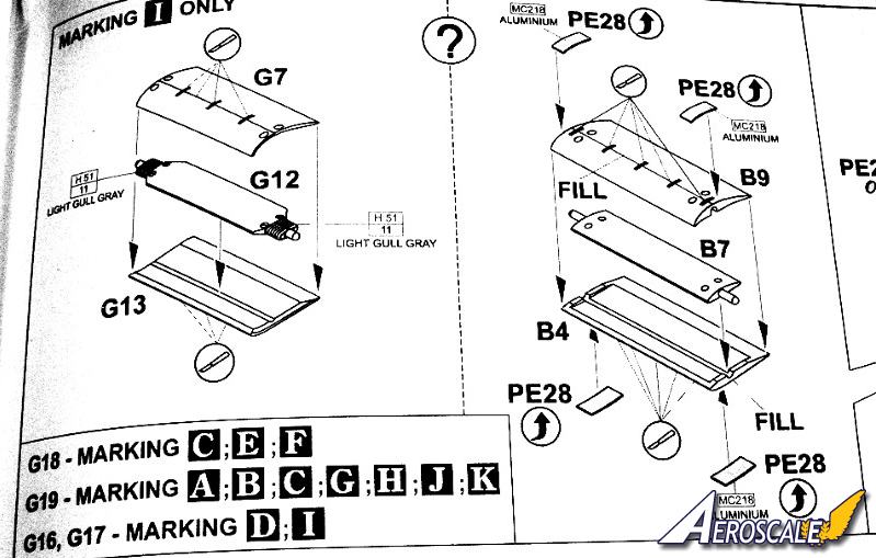
Page 7. Is the axle wing (PP G 7, 12 & 13 ) and wheel (PP B 11 X 2 PE 25 X 2) assemblies. With the wing axle mid section (PP G 12) I routed out the plastic axle and replaced it with a brass rod of appropriate diameter. Next, add the landing gear legs (PP C 23-26 ) to the wing axle (PP G 7, 12 & 13 ). Continue the cabane strut (PP C 9, 15 30 & 31) attachment & PE details.
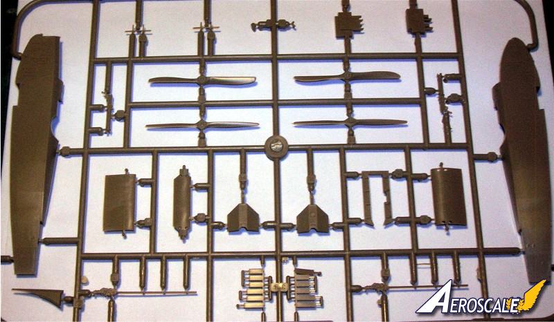
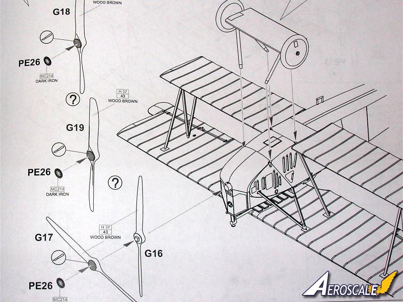
There are 3 types of propellers offered by the kit. (PP G 18 & PE 26) (PP G 19 & PE 26) and (PP G 16 , 17 & PE 26) and note that Eduard has referenced the right application to the profile provide in the kit decals. It is the pitch and length of a propeller that determines the engine application. The paddle profile was the individual company hallmark.
Page 8. The half moon strut attachment points(PE 33 X 16) that Eduard include as photoetch are for the underside of the top wing assembly are a nice touch to add as well. Rigging paths are shown in thin lines. There should be four aileron actuation cables (two on each side for the fuselage) running up into the area behind the rear cabane struts (PP C 9 & 15.) Check your references.
Lozenge Decals
If Microsculpt decals are an A then Eduard's is a B . You have to give them credit. There is only enough kit four colour lozenge supplied for one aircraft. And it will benefit from a translucent coating of dark brown or black overall. This new set has a bit of a greenish cast to them. Though cookie cutter types they are moderately different in pattern locations that Eduard's previous efforts with their 1:48 Fokker D.VII kits.
For this kit those sent to MAG from Fokker - lozenge. The examples we have in the Lafayette Foundation show that the rib tapes were used in one piece on the whole wing rib profile. In general, from the factory Fokker Schwerin used lozenge or clear doped linen strips. Note also that there are cases where whole wing components were mixed at the unit level as replacements. That is the lower wings were one component and the top wing was another. Check which profile you intend on doing.
Marking Options Decals
1.8. Vörös Repülöszázad, Hungarian Red Army, 1919
2.93.07, Hungarian Red Army, 1919
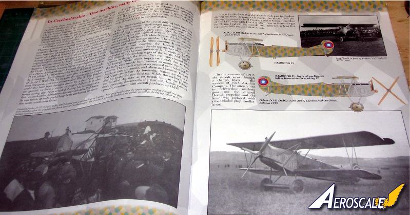
3.W.Nr. 3867, Czechoslovak Air Force, summer 1919
4.W.Nr. 3867, Czechoslovak Air Force, autumn 1919
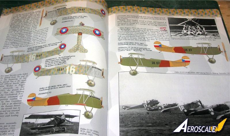
5.W.Nr. 3867, Czechoslovak Air Force, 1920
6.W.Nr. 3867, Czechoslovak Air Force, First Air Meeting, September 1921
7.W.Nr. 3867, Czechoslovak Air Force, summer 1922
8.W.Nr. 3867, Czechoslovak Air Force, summer 1923
9.W.Nr. 3867, Czechoslovak Air Force, late summer 1923
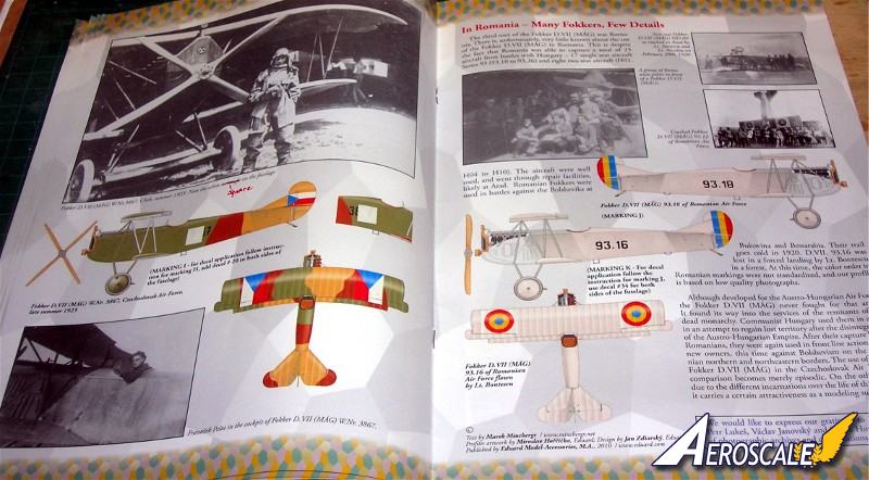
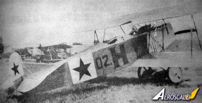
10.93.18 of Romanian Air Force, 1919 or 1920
11.93.16 of Romanian Air Force, Lt. Bontescu, 1920
Specific References
Austro-Hungarian Army aircraft of WWI by Grosz, Haddow & Schiemer , Flying Machines Press, 544 pages.
Flight Report Cross & Cockade Great Britain, Vol. 2 # 4.
Fokker D.VII by P. Grosz, Albatros Pub. Ltd, Datafile #9. 1989, 1993, & 1994.
Fokker D.VII Anthology 1 by R.Rimell, Albatros Pub. Ltd. 1997.
Fokker D.VII Covering Practices by Dan-San Abbott, WWI Aero #102, Pp.22-33. 1984.
Fokker D.VII Detail Marking and Finish of Fokker-built D.VII Aircraft by Dan San Abbott, WWI Aero #107, 1985.
Cross & Cockade USA Vol. 21, #2, P.111
Cross & Cockade USA Vol. 21, #3, P.263
Cross & Cockade USA Vol. 23, #2, P.190
Comments
It is considered a Limited Edition - Dual Combo kit that has almost everything the modeler wants in one box, for thirty dollars more than a usual Dual Combo model kit. Still its a great treatment for a rare subject. Please note the last 3 images here are mine and are meant to compliment the Eduard profile monograph included in the kit.
Please remember, when contacting retailers or manufacturers, to mention that you saw their products highlighted here - on Aeroscale.co.uk
Highs: In my opinion, Eduards kit is a finely cut mold. The black & white exploded view instructions are acceptable. The rest of the kit is well tooled and has become a standard. The average modeler can pick this kit up and get very decent results.Lows: The Eduard lozenge decals have the green and lilac colours locations switched. Verdict: This Eduard kit will become a collectors item. It has great plastic with 11 options, two aircraft kits, express masks for the wheels, optional PE and cookie cutter decal lozenge for one aircraft and a comprehensive slick paper magazine for the profiles.
Our Thanks to Eduard! This item was provided by them for the purpose of having it reviewed on this KitMaker Network site. If you would like your kit, book, or product reviewed, please contact us.
About Stephen T. Lawson (JackFlash) FROM: COLORADO, UNITED STATES
I was building Off topic jet age kits at the age of 7. I remember building my first WWI kit way back in 1964-5 at the age of 8-9. Hundreds of 1/72 scale Revell and Airfix kits later my eyes started to change and I wanted to do more detail. With the advent of DML / Dragon and Eduard I sold off my ...
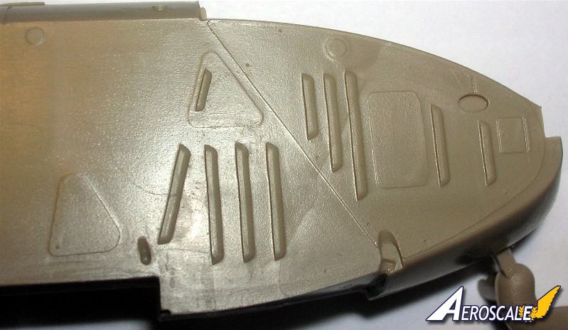
Now lets discuss some differences in the German & MAG built Fokker D.VII airframes. First the MAG built version.
Since the magnetos were located on the front of the Austro-Daimler motor the access hatches were also located at the front of the engine cowlings. So also was the first engine louvre on each side moved back from the normal location. This means the first six delivered from Schwerin had Daimler motors installed and cowlings were modified after they arrived at MAG. The propellers were fitted to the engine type and were of Austro-Hungarian parentage too.
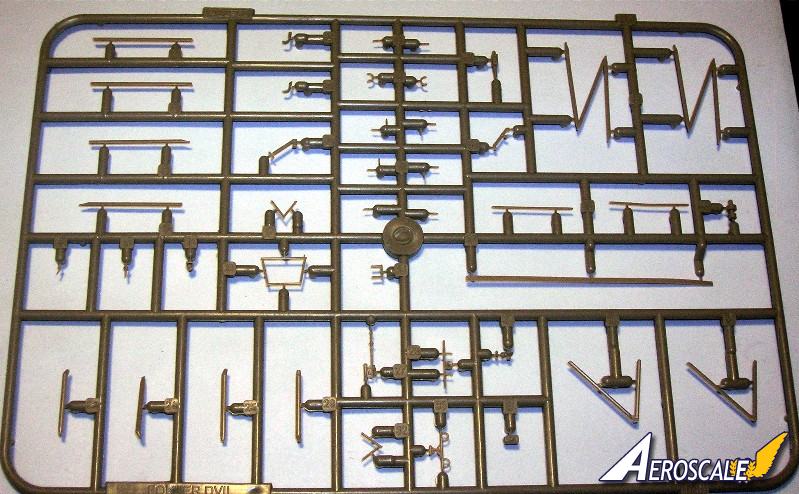
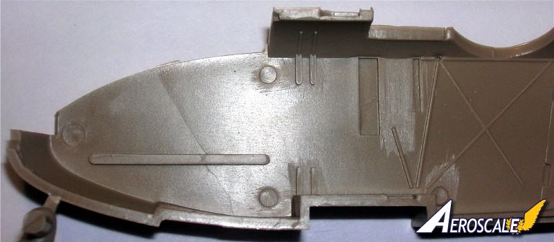
Here is the German version. (The motor here represents a BMW).
If you want to expose the engine by removing the upper engine cowlings you may want to add some simulated structures. Here is a composite from the Royal build noting the kit's lack of engine support structure. Instead a simple shelf is employed.
Here is a full sized modern replica.
Here we assemble the lower wing parts (PP A 2 & 3, B 1.) One could actually insert spars held in place with double sided tape or glued in place. This type of wing assembly is great for the modeler who wants to simulate damage. By thinning down the inner surfaces, internal structure is easy to replicate. Also, before putting the lower wing together sand the vertical edge of the lower wing halves at the roots of all lower wing components (PP A 2 & 3, B 1.) The unmodified fit between the lower wing an fuselage is tight and cause anhedral just like the Roden kit. This fix will eliminate the fit problem. Do Not narrow the whole fuselage by taking away from the center union area.
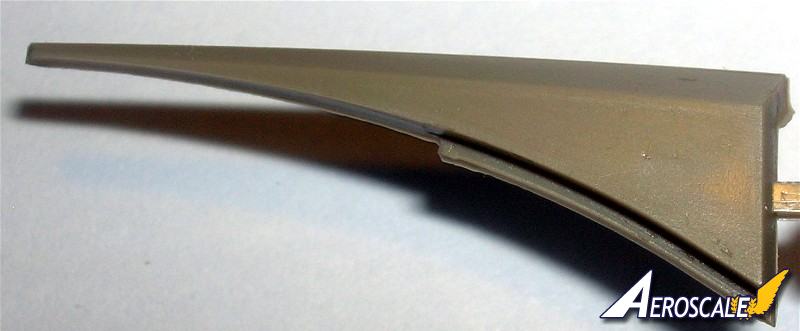
Here three edges are modified and one edge is shown unmodified to let you know how much you need to remove.
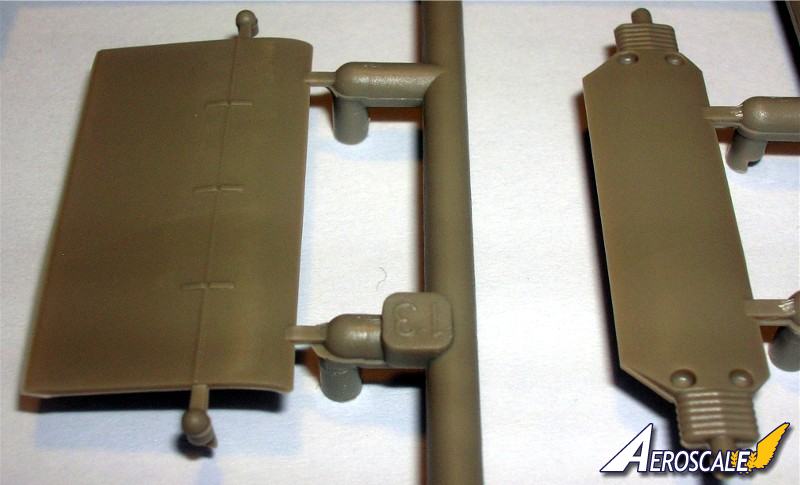
Here is the German axle wing (PP B 7, F 5 & 6 ) with the mid section (PP B 7) I routed out the plastic axle will be replaced it with a brass rod of appropriate diameter.
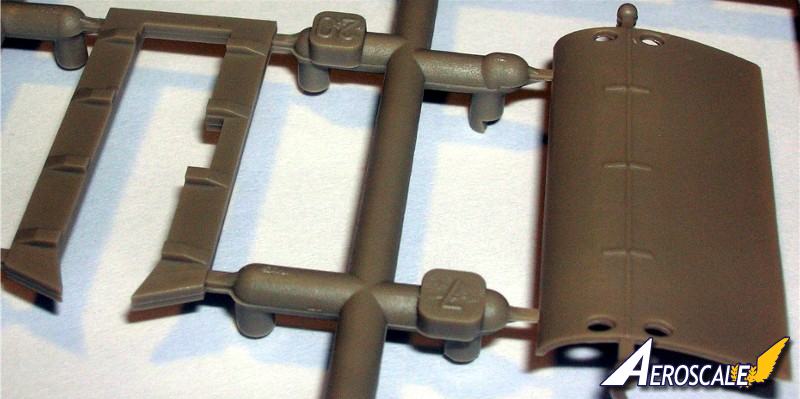
I did the same thing for the "MAG" axle wing. (It seems closer to an Johannistahl "Albatros" version with the exposed shock chords).
Thanks Robert.
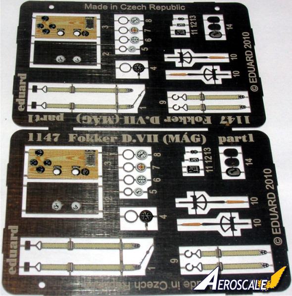
Here is the PE for the D.VII (MAG). More colours and the instrument panel has better wood grain
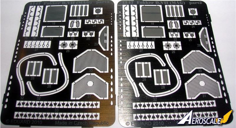
Here is the PE for the German Fokker D.VII weekend kit. Note the differences. This fret contains more items.
This second set of PE from the dual kit has the specific MAG engine and facade details.
You might want to scratchbuild a Schwerin version instrument panel.
The single large bezeled instrument panels in this image are (ex-Jager) resin Schwerin types. Note also the drilled out portions of the Roden kit upper cowlings for the ammunition feed and empty belt tubes. The HGW bezels are coming in very handy.
review here.
Here is the cockpit of the Deutsches Museum original Schwerin Fokker D.VII 4404/18. The gun position has been fared over but the front gun mounts are still inplace. Note the position of the compass as attached to the control column. The interior is overpainted a medium green (probably post war as a method to keep deterioration of the fabric down to a minimum. The instrument panel was painted black and may be a metal replacement item too. But note the instruments and their locations.
This D.VII was found after World War 2 in a barn, probably originating from the Deutschen Luftfahrt Sammlung. Although wearing the registration 4404/18, it is not sure if this is the aircraft's true identity. During restoration it was found that there were many 'non-World War I' modifications, and the Dutch MLD-serial 'D-20' was found.
The center image has a clear, hinged "sneeze guard" over the cockpit.
Fokker D.VII airframes built by Schwerin / Gorries factory.
Fok.VII 227-229/18 prototypes, V.11 and two V.18 brought up to Fok.D.VII production standards.
Fok.D.VII 230 to 526/18.
Fok.D.VII 4250 to 4449/18. Some D.VIIF with BMW IIIa engines.
Fok.D.VII 5050 to 5149/18. Some D.VIIF machines.
Fok.D.VII 7604 to 7805/18. some Fok.D.VIIF machines.
Fok.D.VII 10347 to 10300/18. 37 made, delivered after 11/11/18.


Comments