_GOTOBOTTOM
World War II
Discuss WWII and the era directly before and after the war from 1935-1949.
Hosted by Rowan Baylis
FM-2 Conversion for Tamiya F4F Wildcat
Thearmorer
_VISITCOMMUNITY
Alabama, United States
Joined: June 17, 2014
KitMaker: 121 posts
AeroScale: 118 posts
Posted: Monday, December 15, 2014 - 04:58 AM UTC
This is an attempt at a build review of the old KMC FM-2 conversion set for the Tamiya F4F-4 kit. If I can get the photos to play nice with me I'll press on with this. I know KMC is no longer in operation, but I'm pretty sure some of their conversion sets were obtained by other manufactures and several are still available under different brands. This is a pretty straight-forward conversion with only a couple of simple cuts to the forward fuselage, that follow existing panel lines for the most part. There is a good picture of what is involved on the cover of the box the set comes in.


Well, at least the photo links appear in the post, that's progress I guess. The two exhaust inserts in the fuselage are really the extent of the surgery needed to the base kit. Except for the part through the wing root, it just follows existing panel lines. A little file work and it's done.


Thearmorer
_VISITCOMMUNITY
Alabama, United States
Joined: June 17, 2014
KitMaker: 121 posts
AeroScale: 118 posts
Posted: Monday, December 15, 2014 - 08:18 AM UTC
There is definitely a learning curve involved with this process, after I figured out the whole picture insert thingy, I went ahead and updated the post only to get informed after I expounded at length on the topic at hand, that the system had timed me out. So here goes a continuation of the FM-2 conversion. The flip side of the forward fuselage was painted light gull gray (FS30440) which an old IPMS/USA article said was a good match for "Grumman Gray". Grumman Gray would cover the entire inner fuselage except for the cockpit area, which is interior green (FS34151). Since the fuselage aft of the cockpit will be closed off, nothing was done in that area. Once painted the area forward of the firewall was given a hearty wash of burnt umber artist oil to simulate all the grunge one gets from a reciprocating engine, and then the original color was dry-brushed over the wash. This is the first time I've tried the artist oil wash and I'm not sure I'm quite sold on it yet. Normally I do washes with heavily thinned enamel paint on top of enamel base coats, and seldom have any problems. However, I have had "older" Humbrol enamels get muddy on me after an enamel wash, but Model Master and Floquil enamels seem to work fine.


The strange horizontal shapes in the wheelwell area are the styrene strips I used to reinforce the resin inserts. I felt that since one could look (somewhat awkwardly) up into the wheelwell I needed to do something to make the strips a little less conspicuous. I ground down the edges of the strips and sanded the whole area to get them to blend in a little better.
JPTRR
Staff MemberManaging Editor
RAILROAD MODELING
#051
_VISITCOMMUNITY
Tennessee, United States
Joined: December 21, 2002
KitMaker: 7,772 posts
AeroScale: 3,175 posts
Posted: Monday, December 15, 2014 - 09:33 AM UTC
A "wilder Wildcat" = what a great subject.
Joel_W
Staff MemberAssociate Editor
AUTOMODELER
_VISITCOMMUNITY
New York, United States
Joined: December 04, 2010
KitMaker: 11,666 posts
AeroScale: 7,410 posts
Posted: Monday, December 15, 2014 - 06:48 PM UTC
Nicely done so far. Looks like a fairly straight forward conversion to move the exhausts from the bottom to the sides.

Nice to see that the change in engine to a Wright Cyclone engine from a twin Wasp is included, as well as the correct prop.

Looking forward to following your progress.
Joel


Thearmorer
_VISITCOMMUNITY
Alabama, United States
Joined: June 17, 2014
KitMaker: 121 posts
AeroScale: 118 posts
Posted: Monday, December 15, 2014 - 09:07 PM UTC
Pressing on with this build, the next item that requires attention is the engine. The major difference in the FM-2 vs. the F4F-4 was a change in powerplant. The F4F was powered by a twin row 14 cyl. Pratt & Whitney R-1830 which is nicely depicted in the Tamiya kit. The FM-2 replaced this engine with a single row 9 cyl. Wright R-1820 which resulted in a reduction in weight and a boost in power. KMC provides a detailed resin version of the R-1820 which has close to the same number of pieces as the real engine. Even with all the pieces provided, the modeler will have to provide their own cylinder push rods and ignition wires. My initial idea on the push rods was to fabricate them out of .020 steel safety wire (what looks more like steel than steel?). This idea soon ran afoul of the necessity of filing all the cut ends of very short, very hard, wire pieces. Soon realizing the error of my ways, I opted for Plan "B", the ever popular stretched sprue. The ignition wires are very fine copper wire pirated from some long-defunct electrical appliance and stashed in the spares box. When viewed up close the wire looks very coppery (surprise) but from any distance they have a color very close to the insulation used on the real thing, which will only improve with age and oxidation. The KMC engine comes with a plethora of exhaust pipe sections what come off the cylinders, either due to molding or my ham handed process of cutting them from the pour base, they did not fit at all well. Since I don't plan on opening the cowling and the exhausts won't show inside, I opted not to engage in an exercise in frustration for no good purpose, and left them off. but they're there for those who need them. The air intakes which were mounted in the cowling on the F4F were moved to between the cylinders on the R-1820, these are included as separate pieces (see above) which fit, but not well, and required a little file work to go between the cylinders. A little sanding on the ends of the cylinders and the whole assembly fits snugly into the cowling.

Thearmorer
_VISITCOMMUNITY
Alabama, United States
Joined: June 17, 2014
KitMaker: 121 posts
AeroScale: 118 posts
Posted: Monday, December 15, 2014 - 10:01 PM UTC
The next item of business is my depiction of the "Front Office" of the FM-2. Tamiya did an excellent job of cockpit detail in their F4F-4 kit, the only problem was they apparently used an FM-2 as their reference and included a floor not present in the F4F. What's the problem you say, this is an FM-2, right? Well yes, but herein lies my tale of folly and woe: This whole project was started several years back, before the wonders of the World Wide Web brought the accumulated knowledge of the human race to anyone with a computer and a wire running into their abode. My main source of information on the FM-2 cockpit was/is the excellent Detail and Scale Wildcat book. There is a very good color photo of an un-refurbished FM-2 cockpit therein, unfortunately try as I might, I couldn't tell what the bottom of the cockpit looked like. Was it a dark color, or just not there? Several other references in my possession also failed to resolve my dilemma. At some point I read someplace that the cockpit of the FM-2 did not differ much from the F4F and was open under the rudder pedal troughs. Armed with this bit of misinformation I industriously proceeded to do an outstanding job of converting the Tamiya F4F cockpit to an F4F cockpit, not what I needed. What you see here is my correction of my correction. The white patch behind the joystick is the .030 sheet styrene used to replace the floor I removed (it will be covered by the seat). In my further internet based research I stumbled across a picture of a badly mangled section of FM-2 fuselage fished out of Lake Michigan in the '80s I think. It was a nice top down shot of the cockpit area, the metal parts were in rough shape but obviously cockpit green (FS34151), but on the bottom was an almost pristine bronze green plywood floor. I was in such good shape that at first I thought it might be something they had used to steady the whole thing during the recovery, then I remembered that wood in fresh water will last almost indefinitely. This sent me on a search through my references as to what color this might have been. Elliott's "Monogram Navy & Marine Color Guide" failed to give any color close to what I saw, however, Archer's "Monogram Army Air Forces Color Guide" did have a bronze green color chip. I figured, same country, go for it! Then it was off to my in-house color reference for a close match. What I ended up with was, Aeromaster's Italian Verde Mimetico Green 1, looks good on plastic. (for those of you keeping score at home, remember the fate of Western Civilization does NOT hinge on the shade of green you put on your kits!)

Thearmorer
_VISITCOMMUNITY
Alabama, United States
Joined: June 17, 2014
KitMaker: 121 posts
AeroScale: 118 posts
Posted: Tuesday, December 16, 2014 - 04:33 AM UTC
Having addressed the great floor fiasco the rest of the cockpit was dressed up with the excellent Eduard color photoetch F4F-4 Wildcat set. The level of detail on these sets is simply astounding, far in excess of what mere mortals with hairy sticks can accomplish, at least what this one can do. I will admit though that in support of individual sanity, a nice resin cockpit with a few highlighted details is a lot easier and when buried deep in a dark fuselage accomplishes just about the same thing. Photoetch bucket seats however, to my eye can't be beat by resin. The scale thickness really looks the part. Both the seat and the seatbelts are from the Eduard set. The only other change I made was the bar behind the seat that the belts are lapped over, the kit part has that bar as a solid piece molded to the bulkhead. It is well done but you then have to just drape the harness over the seat. I trimmed the kit piece off with a straight blade x-acto knife and replaced it with that miracle modeling device - stretched sprue. The rest of the kit cockpit details were spruced up with the sometimes infinitesimally small Eduard parts. This brings up the issue of Eduardian Physics, (similar to quantum physics) which states that extremely small bits of physical matter can and will wink in and out of real time/space while being directly observed (more out than in however). Based on my Detail & Scale reference there are a few detail differences between the F4F and the FM-2 cockpits which were addressed by some applied gizmology. Once bottled up in the fuselage only the sharpest of eyes will note the difference. I thought about adding some plumbing and wires but after weighing what would be seen vs. the chance of doing extreme damage to some of the tiny and very fragile details, I decided against it.


How it all comes together:


Joel_W
Staff MemberAssociate Editor
AUTOMODELER
_VISITCOMMUNITY
New York, United States
Joined: December 04, 2010
KitMaker: 11,666 posts
AeroScale: 7,410 posts
Posted: Tuesday, December 16, 2014 - 10:57 PM UTC
DMiller,
First, let me express my pleasure in your writing style. It's laid back, home touch style makes it a joy to read and follow your build blog.

The extra details and corrections you're making are both necessary, accurate, and the viewer will certainly see them.

The supplied Wright R-1820 engine from the kit Pratt & Whitney R-1830 is a perfect example. Your ignition wiring came out really well, and the color looks about right. As for your cockpit adventures, well done. I know next to nothing about the F4F export versions, but the Grumman -3 & 4s had the Interior Green as you described, so there would be no relevant reason for the Brits to change that to their standard RAF cockpit green which was a lot bluer. The wooden floor boards look correct for Bronze Green. You could have gone even a little darker if you wanted to. The overall cockpit really looks quite good.

the headrest was indeed in black leather. You might want to add a slight sheen to it by rubbing your finger on it to rub in some body oil.

Joel
Redhand
#522
_VISITCOMMUNITY
New Jersey, United States
Joined: January 20, 2013
KitMaker: 1,460 posts
AeroScale: 1,443 posts
Posted: Wednesday, December 17, 2014 - 04:29 AM UTC
A very interesting build so far. This conversion came out when I was not active in the hobby, so I didn't even know it existed! "Someday, maybe, perhaps" I'll find time to build the HobbyBoss kit with the Vector conversion.

I did do the "Just Plane Stuff" Tamiya F4F-3 conversion a number of years ago. (Made it an F4F-3A). When I was researching that I saw some info that the cockpit was painted Bronze Green, and that FM-2s were painted interior green. I used Humbrol Enamel 76, which advertises itself as "Bronze Green." Looks close enough to me, and I agree that your floor should be painted like you saw that the real thing appeared.

I don't live far from Linden, NJ, where all those FM-2s were built. Hope this postcard provides some nostalgic inspiration.

Thearmorer
_VISITCOMMUNITY
Alabama, United States
Joined: June 17, 2014
KitMaker: 121 posts
AeroScale: 118 posts
Posted: Wednesday, December 17, 2014 - 05:53 AM UTC
Brian,
Good input, thanks. I picked up several tins of the Humbrol bronze green several years back, Squadron was running a sale on selected Humbrol paints (that apparently nobody else wanted) and I got a box of six for next to nothing. That color was my first thought so I pulled the top card below but it looked too dark and green. The Archer/Monogram chip was a little lighter and blue-er. The Italian Aeromaster "Green I" was lighter than Archer but closer to what I saw on my screen. You'll note that I've got a #75 next to the color name, that was apparently their number in 2000. They may have dropped some colors shortly after and renumbered, which may help explain the Squadron sale. I don't know how well these colors will come across, but they at least should show the shade differences.

Redhand
#522
_VISITCOMMUNITY
New Jersey, United States
Joined: January 20, 2013
KitMaker: 1,460 posts
AeroScale: 1,443 posts
Posted: Wednesday, December 17, 2014 - 06:15 AM UTC
Thanks for the color chip feedback. Beyond that I agree with your comment that an interior color being slightly "off" isn't the end of the world. There are just too many variables of wear, scale effect, etc to get hung up on it.

One thing I will say about the Humbrol color is that for me at least it doesn't look nearly as dark when sprayed on a model. Check out my B-17F build blog and here you'll see what I mean. For me it was a good color to simulate the "dull dark green" that is was supposedly spec on many "early" war B-17s.

I have subscribed to your build and will follow it with interest.

Brian
Thearmorer
_VISITCOMMUNITY
Alabama, United States
Joined: June 17, 2014
KitMaker: 121 posts
AeroScale: 118 posts
Posted: Wednesday, December 17, 2014 - 06:37 AM UTC
Continuing right along for those following this fumbling, these are pretty much the last of the interior fiddly bits. The wheelwell firewall and the main landing gear. The firewall took the paint, wash and drybrush, very well I thought. It wasn't intentional, it just worked out that I sprayed the last of my Floquil lgt. gull gray
(FS30440) and had to drybrush with the Model Master equivalent which is apparently a little lighter. It is however, a sad moment indeed whenever I have to give the "last rites" to one of my dwindling supply of Floquil enamels. I do love them so! The main landing gear(MLG) is still in need of a dirty wash, drybrush and touch-up but the heavy lifting is done. It's a good thing that MLG fits so well because it is one fiddly little assembly. It's all pretty much stock except for the addition of the hydraulic lines and reservoirs(?) towards the top of the struts. They show up prominently on detail photos of the MLG and are easy enough. To their credit, Tamiya attempted to add them, but due to plastic molding capabilities of the time they just come across as a couple of lumps on the strut. My initial thought was to drill holes in a couple of appropriate lengths of styrene rod and add small wire. A check of the misc. parts & bits box(s) revealed some small tubing that just fit the bill, and being one to not waste valuable calories on drilling holes I don't need, I went with it. Otherwise what you see is what Tamiya gives you.


KMC provides the uncuffed prop blades specific to the FM-2, but the kit prop hub has to be used with them, which means trimming and drilling. The blades are well done, but are not keyed, so care has to be taken to get the prop pitch uniform on all 3 blades.

Thearmorer
_VISITCOMMUNITY
Alabama, United States
Joined: June 17, 2014
KitMaker: 121 posts
AeroScale: 118 posts
Posted: Wednesday, December 17, 2014 - 07:35 AM UTC
Brian,
I've been following your B-17 with rapt-enthrallment, to the point where you must stay on task with that. I get positively grumpy if more than three or four days pass without an update on that build. I'll go back and pay particular attention to the nose section again and see how the Humbrol turned out. On a somewhat related note, your use of clear yellow on the wood was a stroke of genius, that is just about the best rendition of aircraft plywood I think I've ever seen. Great job.

Duane
Redhand
#522
_VISITCOMMUNITY
New Jersey, United States
Joined: January 20, 2013
KitMaker: 1,460 posts
AeroScale: 1,443 posts
Posted: Wednesday, December 17, 2014 - 08:28 AM UTC
Aw-jeeze. For the record, it's Tamiya clear orange. New 17 post coming up in a minute.
Thearmorer
_VISITCOMMUNITY
Alabama, United States
Joined: June 17, 2014
KitMaker: 121 posts
AeroScale: 118 posts
Posted: Wednesday, December 17, 2014 - 08:30 AM UTC
The shot below is a dupe of one previously posted but it shows a couple of items I want to elaborate on before I close things up. Actually it only shows one of the things, the other, a spacer I placed behind and under the cockpit assembly is not shown. I will cover what you can't see first. Typical of aircraft kits of this era (1935-1945) the aft cockpit bulkhead and fuselage dorsal spine don't always (as in seldom) line up. The Wildcat kit is no exception. The cockpit assy. with a little care, fits snug in the front by the firewall but the aft bulkhead leaves a gap when mating the upper fuselage halves to the wings/center section. There's a couple of tabs under the aft section but they don't hold it up enough. Nothing leads to frustration like getting a really spiffy cockpit put together only to have to scuff it up and get sanding dust into everything from having to putty and clean-up a big gap where everybody can see it. My solution in this case was to make a shim out of .030 sheet styrene. The shim was about 0.6 inch (1.5cm) long and tapered from 0.4in. (1cm) in the front to 0.6in. (1.5cm) in the rear. It was small enough to fit in between the end of the cockpit assy. and the end of the center wing section. I then fitted one side of the top fuselage halves and slid the shim forward until the top of the bulkhead was up snug with the top of the fuselage. I then glued the shim in place, and completed the fuselage assembly. My shim did't completely eliminate the gap but the result was a big improvement. The bulkhead was snug with one side but it did leave a slight gap of the side I couldn't fit and shim.
The item you can see is at the top of the picture in the wheelwell. The silver box structure in the center of the wheelwell is the intercooler and it's associated plumbing that was located on the left side of the wheelwell on the F4F. With the new R-1820 the intercooler was moved to about the location you see here. Unfortunately the picture reference I saw indicated a more oval shaped object (at least in profile) for the intercooler. Well, since the existing intercooler looks pretty neat with a little weathering, and I was fresh out of oval-ish things, and the wheelwell is a pretty cluttered affair in the real Wildcat, I applied the "First Law of Gizmology" (if it looks plausible - use it!) and stuck it in.


A close look at this shot will shot the portion of the aft cockpit bulkhead I had to fill to get a good fit. (the white strip above and left of the headrest (as your looking at it))

Joel_W
Staff MemberAssociate Editor
AUTOMODELER
_VISITCOMMUNITY
New York, United States
Joined: December 04, 2010
KitMaker: 11,666 posts
AeroScale: 7,410 posts
Posted: Wednesday, December 17, 2014 - 10:21 PM UTC
DMiller,
I'm really enjoying your build blog. Great build, and well written in your most easy style.

I've run into similar problems with bulkheads, or various internal parts that end up having a gap that can be seen. Your solution works, but as you said, it will require sanding, some putty work, more sanding, and polishing. The result is dust everywhere that is difficult to completely get rid of, and more repainting the should be necessary.

A perfect solution is Vallejo White Acrylic putty. The long tip applicator works 8 out of 10 times, for the other times you can use any applicator to apply the putty. You simply put it on, give it 1 min max to set up, then using a damp Qtip gently wipe it so that it's only left in the opening. It does shrink, so a 2nd application would be necessary to completely fill the gap. I've use it all the time, and it really solves a lot of issues.

Joel
Thearmorer
_VISITCOMMUNITY
Alabama, United States
Joined: June 17, 2014
KitMaker: 121 posts
AeroScale: 118 posts
Posted: Friday, December 19, 2014 - 08:43 AM UTC
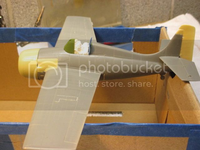
Continuing on with the build, with the cockpit assembly shimmed up to the left upper fuselage half it was time to mate the upper halves to the wing/lower fuselage section. It's a little fussy getting the three sections all in the right place at the right time, but not bad. I think it helps having the cockpit-wheelwell details in the wing section secured and centered as opposed to trying to secure one side and then mate the other, or worse yet, trying to trap misc. parts between two sides. The wing root join in this kit is excellent, even the join with the resin inserts looks good. I ran a strip of masking tape from wingtip to wingtip over the fuselage to keep everything snug and let it dry.
There was a slight gap on the underside where the wing section met the fuselage halves and a slight step just forward of the wing leading edges where the resin inserts met the lower wing section but nothing of import.


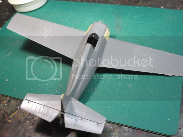
The white arcs in the photo are the fill in the gap between the fuselage sections, as you can see nothing significant. The only downside on this, and it's only a player if your looking for it, is I opted to not rescribe that particular panel line. I used Squadron putty to do my fill because it's easy to sand, flip side is it also chips out easy. I figured my scribing chip the putty out and I'd have to do it all again, best to leave well enough alone. The brownish ovals are the original F4F oil cooler locations which are depressions that require fill since they were removed on the FM-2/ The white rectangles and lines are the outer .50 cal. ejection ports and panel lines. To save weight and boost performance the outer .50's were removed from each wing. Same with the white lines on the top of the wing, fill and sand smooth. I rescribed the major panel lines on the top and bottom of the wings, but still a little detail is lost, a lot of rivets disappeared. With a ponce wheel and say, a major immobilizing injury I might replace those rivets, but not this week. In conjunction with the addition of the cockpit floor, the underside windows were deleted on the FM-2. The kit windows were installed as fillers blended in and sanded smooth.

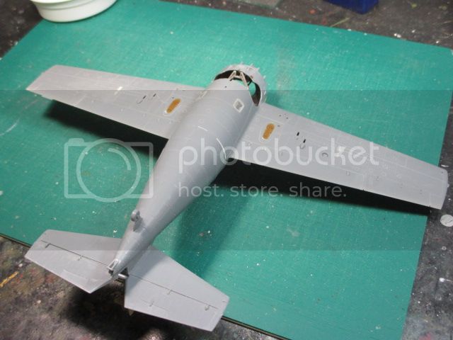
A couple of shots of the resin parts before priming. The cowling and engine are just stuck on at this point (for appearances) but the rudder and tail extension are fixed. The KMC FM-2 rudder and extended tail are one resin piece and meant to be attached as one piece. The resin tail extension is a little thinner than the existing tail top on the Tamiya kit so a little blending is in order here. I did not like the way the combo rudder/tail piece fit on the existing vertical stabilizer, and if feasible I like to offset the rudder on my models slightly to give a more candid appearance. In this case I felt it would help the fit as well. The new problem is, you've got a very small piece that only butt joins to the adjacent piece (can you say fragile!). The extension piece is so thin that drilling a hole for a reinforcing wire would have it's own set of hazards. In the end I opted for the butt join and hoped for the best.


Thearmorer
_VISITCOMMUNITY
Alabama, United States
Joined: June 17, 2014
KitMaker: 121 posts
AeroScale: 118 posts
Posted: Wednesday, December 31, 2014 - 06:34 AM UTC
Well having survived another Christmas and my most recent encounter with those small but potent vectors of disease, lovingly known as grandchildren, it is time to get on with this conversion. I primed with a light gray floquil railroad color thinned with lacquer thinner. I prefer to thin all my enamel paints with lacquer thinner for airbrushing, it gives a good even coat, dries quickly and bites into the plastic a little and doesn't peel. The down side is I usually waste a little paint at the end of each color because it is best not to put the thinned paint back into the original bottle. I've had consistently bad results putting thinned paint back with the original. This even holds true when using the paint manufacturer's own thinner. If I have a bottle that's starting to thicken up, (Model Master comes immediately to mind) I'll put a few drops (or globs) into a mixing dish and then thin that to use, putting it back just hastens the process of the paint separating. After checking results, the usual touch-up re-sand and repeat ritual went on for a couple of rounds until things looked passable. The switch from a double row engine to a single row one, presents an opportunity for some creative thinking. The R-1820 will need to be spaced out to fit the new cowling correctly. My first idea was to use a circular portion of the clear sprue which just happened to be the right diameter to fit over the rear gearbox portion of the engine, and had a couple of relief gates on one side to give more depth. There were only two, which was way too shaky, so I cut a couple of additional sections and glued them on. See below:


This looked marginally acceptable, but would require more hacking and slashing to get it to fit on the firewall correctly. I was about to commit myself to more fiddly work when I happened to look in the box where the unused (and about to be used) parts were rattling around. My eyes then fell upon the back row of the original wildcat engine, it was an eureka moment! It was already designed to go on the firewall, all I had to do was drill/grind out the center to accept the new engine and sand the front to the correct depth. This was the final solution. The cylinders of the R-1820 line up well enough with original kit part, that with a little dark paint it won't be seen in the cowling. You'll note the the R-1820 is a little skewed in the photo (the top cylinder should be at 12 o'clock) it's not secure and slipped.


Redhand
#522
_VISITCOMMUNITY
New Jersey, United States
Joined: January 20, 2013
KitMaker: 1,460 posts
AeroScale: 1,443 posts
Posted: Wednesday, December 31, 2014 - 06:47 AM UTC
Re the R-1820 depth, I would have thought the cowling was a shorter chord and that that would eliminate the "depth" problem. The KMC set didn't give you something to mate engine to firewall?

Is the KMC cowling accurate? If not, consider using the Vector one for the HB kit. How does the KMC cowling compare to the "R-1830" Tamiya one?

The overall build is looking very nice BTW!
Thearmorer
_VISITCOMMUNITY
Alabama, United States
Joined: June 17, 2014
KitMaker: 121 posts
AeroScale: 118 posts
Posted: Wednesday, December 31, 2014 - 07:49 AM UTC
Having solved the engine mounting problem to my satisfaction, it was time to move to the back of the plane. The original kit wildcat tail has an antenna mount molded on top of the rudder, unfortunately the resin replacement rudder lacks this necessary feature. To further complicate the issue, the new rudder is very thin and comes to a knife edge on the top. This precludes drilling a hole to accept a new antenna mount, what to do? I decided on using a short piece of copper wire as the antenna mount, but much scratching of head and gnashing of teeth ensued as to how to get said wire attached to said rudder. I finally resigned myself to having to cut a notch in the top of the rudder in-line with the rudder hinge to accept the wire. This solution presented a new dilemma: attempt the fix in-place, or remove the rudder to be able to work better? If the rudder is on with superglue it might twist off pretty easy (weak shear strength) but if it's epoxied and has something to grab onto, it could get messy. Now I'm having a "Dirty Harry" moment. "Well punk this is 5-Minute Epoxy, the strongest epoxy known to man, and it'll rip that tail right clean off. Now, you've got to be thinking, did he use it of didn't he? You know in all the excitement I kind'a forgot myself. So, are you feeling lucky Punk? Well are you Punk?" I flinched, wimped out and decided to try to do the fix in-place. I broke out a fine razor saw (below) and cut a small notch in-line with the rudder hinges.


That went well enough, now the trick was getting the right amount of superglue to hold but not so much as to make a mess to blend back in. There was also the problem of knocking the wire back out in the clean up process or damaging the surrounding parts. I sprayed a little accelerator on the area to set things up when I was satisfied with the placement and then went at it with jewelers files and a little sanding. Using the accelerator helps because it hardens the superglue enough to hold but also leaves it softer than a full cure, thus easier to work. It all went much better than I expected.


Thearmorer
_VISITCOMMUNITY
Alabama, United States
Joined: June 17, 2014
KitMaker: 121 posts
AeroScale: 118 posts
Posted: Wednesday, December 31, 2014 - 07:57 AM UTC
Brian,
I wouldn't entirely fault KMC, I've had this conversion kicking around for an extended period of time and several moves. I could have misplaced part of the advice on assembly, plus I did not attach the exhaust stacks which would account for some of the missing depth. KMC may have included some instruction on mounting the engine but at this point I don't recall for sure. The cowling looks good relative to reference material so I suspect the fault lies more with me not KMC.

Duane
Redhand
#522
_VISITCOMMUNITY
New Jersey, United States
Joined: January 20, 2013
KitMaker: 1,460 posts
AeroScale: 1,443 posts
Posted: Wednesday, December 31, 2014 - 08:22 AM UTC
I hear you. That tail looks good.
VonCuda
_VISITCOMMUNITY
North Carolina, United States
Joined: November 28, 2005
KitMaker: 2,216 posts
AeroScale: 1,080 posts
Posted: Wednesday, December 31, 2014 - 11:22 AM UTC
DMiller,
Reading this build blog, I almost feel like I'm having a conversation with myself. If I had a twin brother, you would be him. I am imagining you slumped over your workbench with squinted eyes and dried glue all over your fingers cursing the plastic, the instructions, and the world in general in a low mumble. I see tiny parts flying off the bench to be eaten by the carpet monster while the phone rings off the hook and the dog is in the next room barking at a siren on the television.

If you also have the deep southern accent like myself, we may indeed be related. I'm enjoying watching your progress and your....our....dry sense of humor.

Thank you sir.
Joel_W
Staff MemberAssociate Editor
AUTOMODELER
_VISITCOMMUNITY
New York, United States
Joined: December 04, 2010
KitMaker: 11,666 posts
AeroScale: 7,410 posts
Posted: Wednesday, December 31, 2014 - 11:59 PM UTC
Duane,
A really outstanding build so far.

I did a quick Google search on the Marlet 11 to see if it was shorter then the F4F-3 since there was a significant engine change. Interesting to note that the cowl was exactly the same in dimensions, even though the engine was a single not a duel cylinder bank, minus the carb intake duck on the top. I'm assuming that this was done so that there was no changes to construction jigs or assembly of the basic cowling, and those changes required were just different panels.

What I still don't understand is how they made the correction for the difference in width of the two engines so that the prop cleared the cowling.

Joel

VonCuda
_VISITCOMMUNITY
North Carolina, United States
Joined: November 28, 2005
KitMaker: 2,216 posts
AeroScale: 1,080 posts
Posted: Thursday, January 01, 2015 - 01:57 AM UTC
Joel, my guess is that the engineers used something like the KISS method and simply used a type of spacer to push the new engine out to the correct distance. Longer bolts, spacers, and perhaps some strategically placed braces sounds simple enough. Then again this is all a guess on my part.
 _GOTOTOP