

1⁄35Zeppelin Staaken R.VI
33
Comments
A severe case of Advanced Modellers Syndrome
Anyone who has ever purchased a kit that seemed daunting or too much may find this of some interest. Vacuforms, resins & white metal, production or aftermarket, kits or conversions its all good. I dealt with all these subjects beginning with the day I heard a thump at my front door. I found the mail carrier had left behind and object that, due to its size and weight probably forced his medical retirement.There was a time when all I built was in 1/72 scale. I remember that I had joined the Kit Collectors Clearing House out of Edmond Oklahoma USA back in 198. From their pages I eventually found a fellow modeler that had a Contrail Zeppelin Staaken R.VI for sale at $25.00 USD. The box (more like a small crate) arrived on 16 June 1982. The kit had already been on the market since May 1979. Within the kit itself I found three large sheets of vacuformed white polystyrene plastic containing the wings (23 inches long), fuselage and empennage. There were large chunks of injection molded plastic pretending to be engine heads, exhausts, radiators, propellers. The decals were large but under nourished flanged Iron Crosses. There was a basic plan drawing with an exploded view for the ultimate locations of the kit parts. This also included the instructions for doing either a Land-based type or the Naval Floatplane version with historical notes. Contrail had used a relatively new type of molding process for this kit. Female molds were used to draw the heated plastic into their recesses. This allowed for more detail to be represented on outside surfaces than was seen on vacuforms made with male molds. Now as we have entered the new century, vacuforms tend to be passe to most modelers. While they seem to have been replaced by the use of resin/rubber vulcanizing or low pressure, short-run injection molding there are still several superb companies that manufacture high quality vacuform kits. Long live multimedia!!!
It was vacuform kits that kept alive the interest in modeling subjects of First World War aviation. Then the Cottage Industries started moving steadily away from their beginnings with vacuforms to small short run injection molding kits. Veeday, Merlin (both run by Vagn Espensen), Pegasus/ Blue Max (Chris Gannon), Classic Plane (D. Schörsch), Formaplane of London, By-Planes (Pamela Veal), Rareplanes of Canada, AirFrame (John Tarvin), CramerCraft and countless others all gave us a steady stream of historic plastic. One of the premier companies at this time was of course Contrail, part of Gordon Sutcliffe Productions, Somerset, England.
History
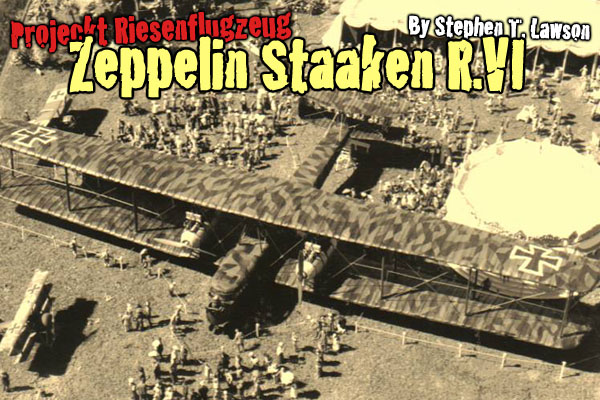
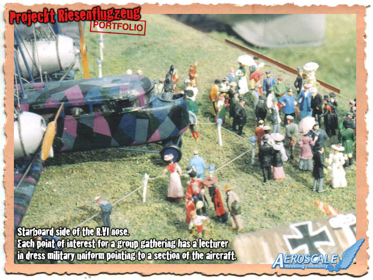
Eighteen examples of the Zeppelin Staaken R.VI were built by a total of four different contractors. The profile seen here was built by the parent firm, Staaken Werke, Berlin. R.VI 31/16 left the factory with four 245 hp Maybach D.IVa engines. This power plant combination was usually seen on the Naval Staakens type L with floats. She was accepted in January 1918 and is seen here before her assignment to Riesenflugzeug Abteilung 500 at Custinne airfield in France. It was thought to be covered in Splinter pattern lozenge camouflage. Notably its sister the R.VI 30/16 was covered in a more Regular pattern where each lozenge was closer in size and shape to its neighbor. Staaken was the only builder to use the both cross colours of black & white. The others used only white borders. The R.VI 31/16 crashed at Beugny near Pronville on the night of September 15/16, 1918. On that mission she was caught in a group of searchlights and a Sopwith Camel night fighter (D6102) of RAF 151 sqdn fired 500 rounds into the fuselage and engine nacelles. The British pilot, Lt. F. C. Broome saw the fire break out in tremendous severity. The German pilot, Lt. Wohlgemuth left the his chair of R.VI 31/16 and ran to the aft gunners station calling for his crew to abandon the giant ship. The pilot was the only member to survive. Its wreckage was given the British capture number G/3rd/24.Projeckt Riesenflugzeug
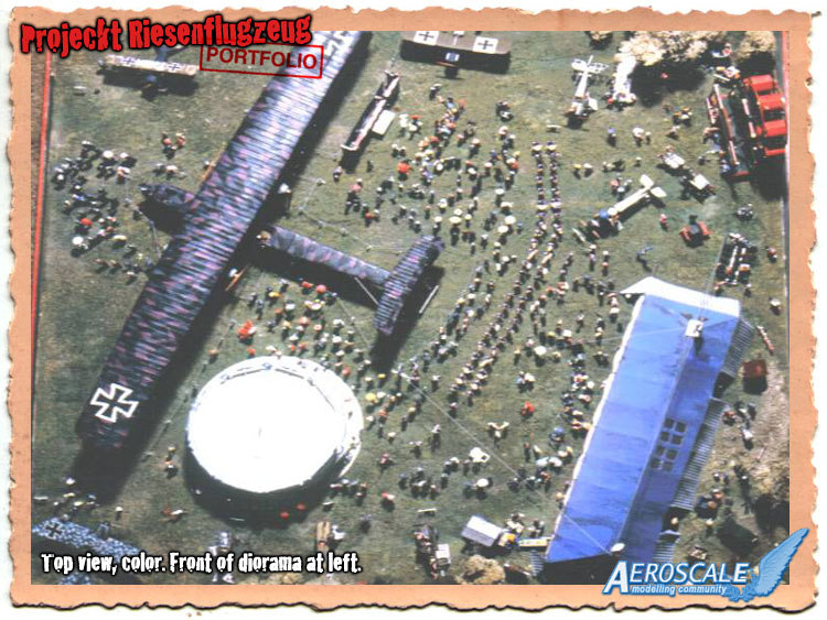
The premise for my attempt began with an old Model Magazine issue of February 1982. Before Albatros Productions Ltd., Mr. Ray Rimell wrote the premier build up of the Contrail 1/72 scale Staaken kit. Some of his terminology was unknown to me so I had to do a little creative-guessing. I decided to begin work on the giant in October 1982 and I finished on 1 August 1990. Even after I was finished I saw things I could have done differently. I chose a piece of new 3/4 inch A/C grade plywood. On the finished side and I glued down a copy of the 1/72 scale (Scale Models #3029) plan views. I began to plan the jig, I was going to need to bring the whole kit together, trued and square. The aircraft was wedged between glued blocks of Bass and Balsa woods attached to the plan board as the kit came together. I had built a cover out of 1/4 inch plywood to protect it when I was not working on the kit. The landing gear went on last so the kit could sit flat at all times. Even then I knew this would have to be a diorama. The scale acreage around the Staaken was massive and empty.Construction of the kit
Step 1Begin by discarding the lower surface halves of the wings and replace them with 0.020 thou. sheet plastic. The top wings halves were about .050 to .060 thou. thick, so there was a lot to work with. The upper wing and the lower wing spars should each be a single length of 1 inch X 3/8 inch Bass wood, tapered at the ends. Glue these to the undersurface of both upper and lower wing halves. Now add the sheet plastic as the lower surface.
Contrail had attempted to put scallops in their kit wings at their trailing edges. It took a great deal of work (sanding and filling) to get wing surfaces looking right. I then glued cap strips on the upper surfaces to represent the wing ribs. The lower surface ribs were simply heat-stretched sprue. Since then Plastruct has come out with thin strands of plastic in uniform diameters and lengths. Drill all strut and rigging holes for the wings and fuselage at this time.
Step 2
Plug 1/3 of the rear fuselage halves with a resin pour mixture. I opened the cabin windows and the lower wing spar slots with a sharp razor knife. These slots must match. I added the interior based on existing photos and Mr. Rimells article. Internal Structures and Station Bracings are not fully known, so some creative engineering may be needed. Plastruct sells cylinders that can be altered to look like the main fuel cells. Fotocut has Harry Woodmans brass detail set available. These will dress up the cockpit cabin nicely. Unless one or more of your cabin windows are open, not much will be seen in this scale. The basic colouring here is wood flooring and framework. leather seats with metal fixtures or skeletal structures being black or grey. Facades for the bomb bay and ventral-gun positions should be added. My tail skid was a large diameter brass-rod shaped in a square cross section, bent and seated deep into the resin plug. The clear plastic I used for the cabin windows was from Preiser. Today I would use the clear sheeting from Evergreen Plastics, also applied as a last step. Check your references.
Step 3
Brave is the heart that does it complete... The nacelles can be built as complete as your heart dare. Even with resin Engine kits out today no one yet has done the 240hp or 260hp versions needed. Scratchbuilding was my best bet. My engine cylinders were all made from wooden dowels cut and shaped with a motor tool then sealed with gloss laquer. Now, I know that most 1/48 scale engines of the inline six cylinder type could be modified for the 1/72 version of the Maybach Mb.IVa 245hp or the Mercedes D.IVa 260hp. These were very large motors with the measurement of 200mm from cylinder center line to cylinder center line (The average distance on the Mercedes 160-180hp from cylinder to cylinder was 172mm). Only the crank cases will be visible at their back sections (to some extent) and the upper water-jackets of the cylinders. I decided to install four scratchbuilt replicas of the Maybach engine (six cylinders). This was mostly due to the fact that I had the materials to do the job and decided not to buy four resin 1/48 motors. Temporary cradles of scrap plastic can hold the nacelles in place while the glue sets on the struts passing through them to the wing locations. The radiators are scratchbuilt on plastic cores and fine screen mesh added. Your local model railroad hobby store should have what you need. The spares box should yield propeller shaft retainers (mounted on the fire-walls) and carburetor intake pipes from other World War One fighter aircraft. These can be used as guides for the propeller shafts. I chose to scratchbuild mine. Warning!! If you use resin items such as engines do not use any metal rods for struts and supports other than brass. Some resins do use formaldehyde in their manufacturing process. This type of resin only cures up to 91 - 96%. Thats why you get that oily sheen on some resins. When this type of resin comes into contact with piano wire, unpainted florist wire or other white metal wires, over a period of a week or two it will begin to rust and decay. Fortunately brass wire/ rod wont react this way.


About the Author


FROM: COLORADO, UNITED STATES
I was building Off topic jet age kits at the age of 7. I remember building my first WWI kit way back in 1964-5 at the age of 8-9. Hundreds of 1/72 scale Revell and Airfix kits later my eyes started to change and I wanted to do more detail. With the advent of DML / Dragon and Eduard I sold off my ...
Comments

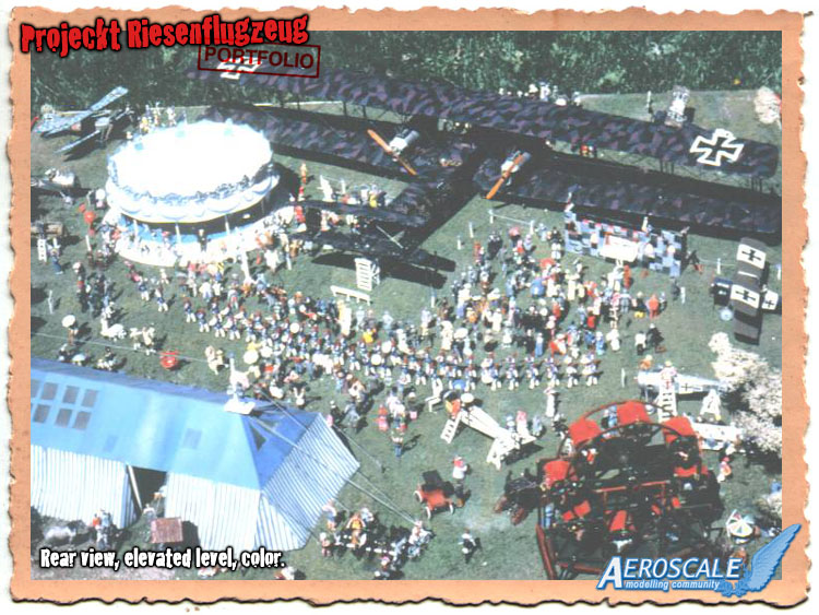
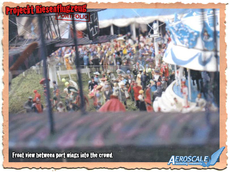
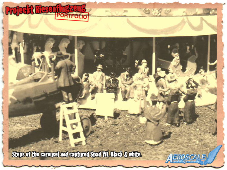
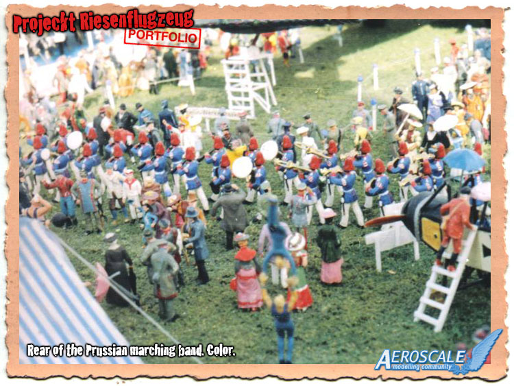 This is another view of the crowd at the back end of the Prussian band. The circus tumblers seem to be warming up for their performance, later in the tent. At the upper left you can just see the circus strongman wiping his head and the barbells that the little girl has lifted over her head. The crowd is displaying mixed emotions. Another great advantage to the Preiser figures is their use of the stance and gestures of the posed figure to convey emotions and activities. Even in this small scale you know whats going on.
APR 08, 2007 - 03:24 PM
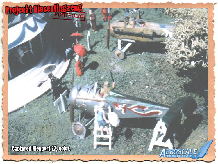
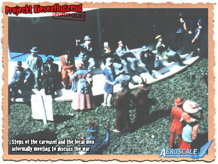
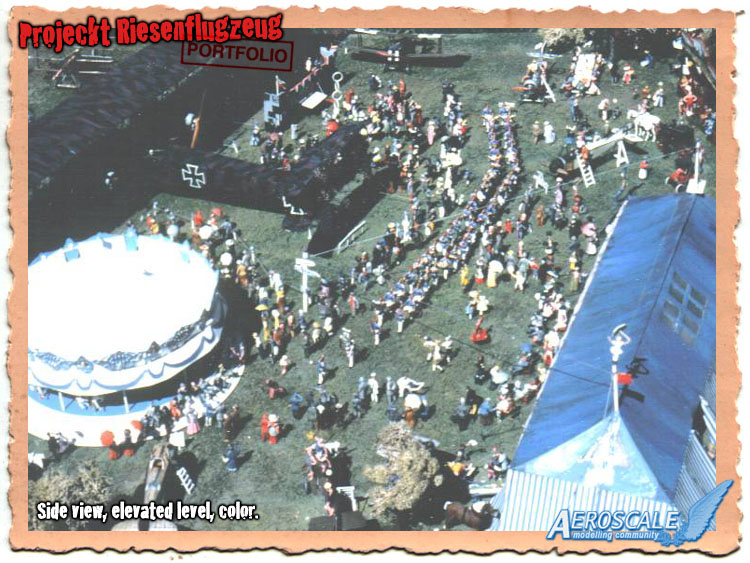
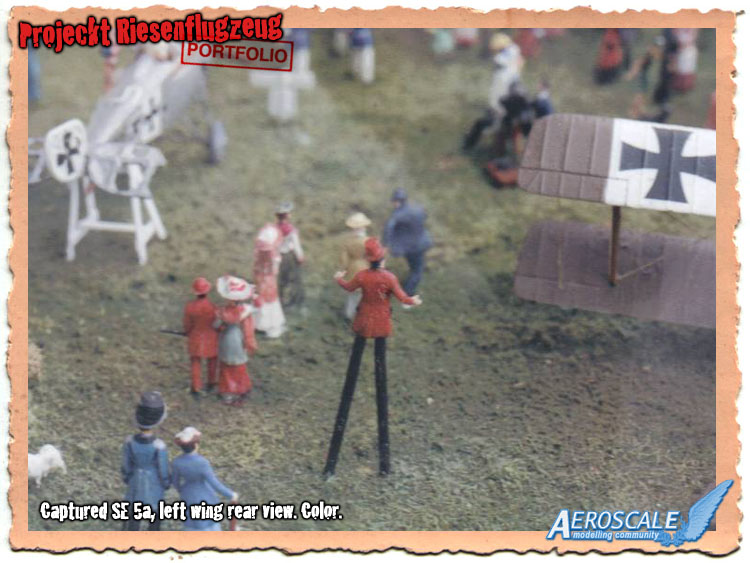 Here is the other circus tall man between the captured Nieuport 17 A'313 and the SE 5a. More of the figures that appear to be just arriving are seen walking into the diorama. This conveys to a small extent the unseen porton of the diorama. This can be seen here and at the rear of the beer tent area. The one thing I really wanted to portray was the train and passenger cars that were used to ferry the citizens into the area. One was available at a $300.00 USD price tag and with a govt. employee pay check and four (later 5 ) children, I just had to exclude it.
APR 08, 2007 - 03:35 PM
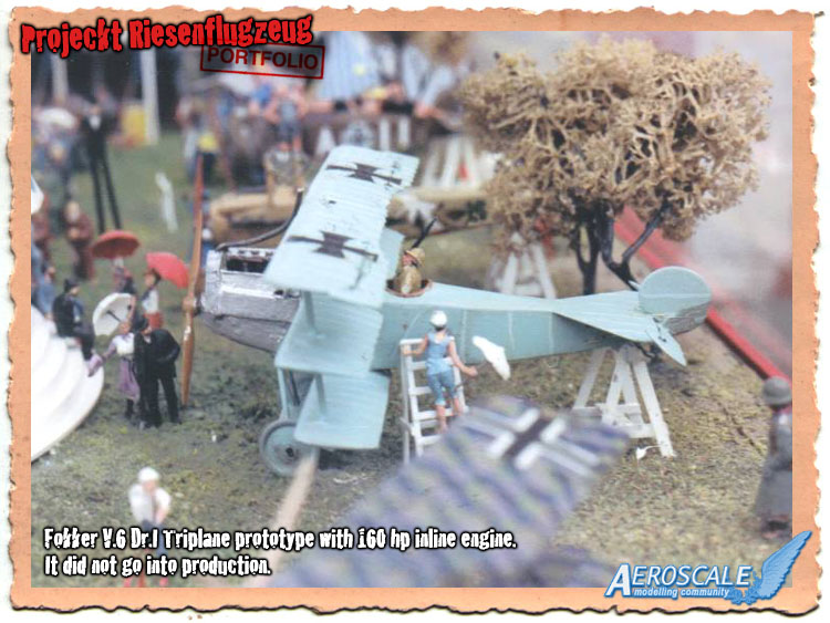
 This represents the experimental Fokker V.4 works number 1661. It is a conversion of the old Revell Fokker Dr.i kit. Wings shortened surface details altered. Ailerons were trimmed to represent the unbalanced versions. Horizontal tail surfaces modified, struts replaced with cut and shaped steel rod. The kit engine was replaced with an Aeroclub 110hp LeRhone. Cockpit is scratchbuilt. Originally designed as a biplane and changed in July 1917 to the triplane configuration. It served at a test bed for this configuration. Later after modifications it was sent to Austria to the MAG factory for testing there.
 APR 09, 2007 - 08:59 PM
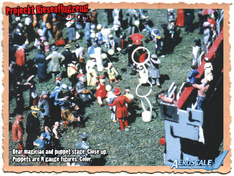
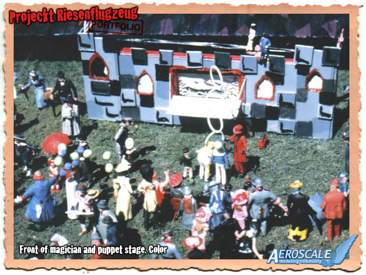 Here I have depicted a large puppet show of the type popular in Europe around the turn of the century. In the front a magiciqan performes the spinning ring gag. The puppets seen at the top of the "stage" are Preiser "N" gauge figures also 1900 era. At the lower left you can see the 'Tramp" clown and a beat up Hydrogen bottle for the children's balloons. Helium was the export of the USA and preWWII though safe was not cheap. So in Europe Helium was almost never used. As with the rest of the diorama one can see everything from swimsuits to uniforms. Children and wives often dressing in sympathy to their father/husband's uniform.
APR 12, 2007 - 03:47 AM
 Now we have come full circle. The Revell Fokker Dr.I triplane initially installed was replaced. I had it in Jasta 36 markings with the name "Thor" on the top wing. I had actually decided early on to replace the model but as it suffered the same damage as the Albatros D.Va the choice was made for me.
 APR 14, 2007 - 07:26 AM
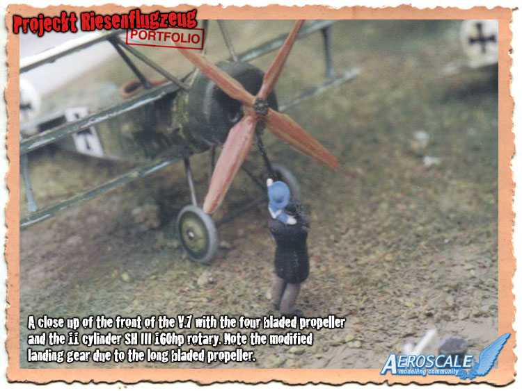
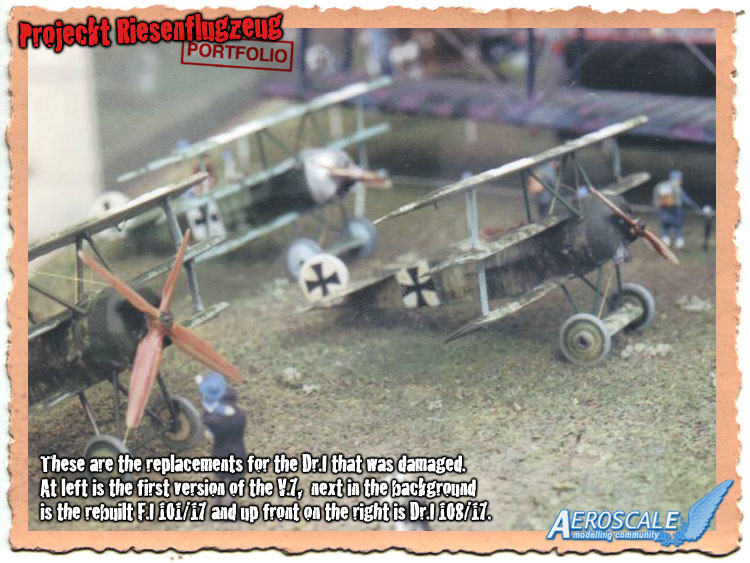 These were the items I grouped together to replace the original Dr.I. I was faced wit adding more figures or more aircraft top fill the space. As mentioned before I had been building the testbed aircraft for the Triplane configuration and decided to include. Here we have a model representing the rebuilt 101/17 , w/n 1697 (it was tested to destruction in the eval phase of the prototypes.) out front, Dr.I 108/17, w/n 1776. Not much is known about this machine but it might have been the first production trainer of the type. No guns and a Goebel Goe.II 100hp rotary. The last airframe is w/n 1788 with the big four bladed prop and 11 cylinder Seimans Halske SH.III. This is the first airframe of four called V.7. The engines were white metal items from Aeroclub. The four bladed prop was made from two spare Airfix Hannover CL.IIIa types. They were Lincoln log cut and matched together.
 APR 14, 2007 - 07:43 AM
 It finally happed just as I was about to sign off on this thread. . . Someone has asked me. ". . . Hey Stephen whats in the tent?. . "
Just about everything. At one end the simulated bread and food stores from the various Preiser kits involved carts, crates and pallets. Like the blue and white canopy wagon under the tree. At the other end a wall of art works and a sculptor hard at work. ( Another sculptor was used at the puppeteer in the outside stage. ) In between the two settings in the tent are tables and chairs and at the back of the tent centrally a stage with a small room for a doctor and nurse to perform physicals and an Army recruiter. (who would have thought at a carnival hosted by the military. . . Men hauling in sacks and crates, vendors selling and even by the recruiting station. . . more beer kegs.
It finally happed just as I was about to sign off on this thread. . . Someone has asked me. ". . . Hey Stephen whats in the tent?. . "
Just about everything. At one end the simulated bread and food stores from the various Preiser kits involved carts, crates and pallets. Like the blue and white canopy wagon under the tree. At the other end a wall of art works and a sculptor hard at work. ( Another sculptor was used at the puppeteer in the outside stage. ) In between the two settings in the tent are tables and chairs and at the back of the tent centrally a stage with a small room for a doctor and nurse to perform physicals and an Army recruiter. (who would have thought at a carnival hosted by the military. . . Men hauling in sacks and crates, vendors selling and even by the recruiting station. . . more beer kegs.APR 19, 2007 - 03:34 AM
Staaken factory film images.
Production Company: Messter Film GmbH (Berlin)
Copyright:
Federal Archives
Category: EFG1914 - Movies from 1 World War II , film
Giant aircraft "R.VI" (license built Gotha Coach Factory) is pushed into Staaken from the airship hangar, the crew gets into the aircraft; engines in the nacelles are started; launch preparations; civilian passengers go with hand luggage on board, a box is from the open cars on the plane loaded, start the "R.VI"; aerial photographs of Potsdam, New Palace, Havelbucht, Observatory and Holy Spirit Church;; landing on an airfield (taken from the right engine nacelle) pilot in the open cockpit during flight.
Source: German Federal Archive
AUG 28, 2013 - 12:46 PM
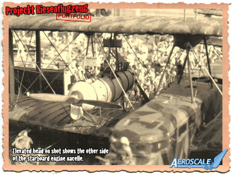
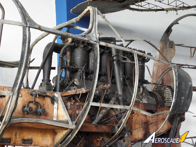
 The engine Gondola to a Staaken.
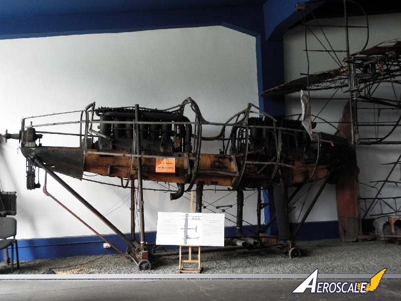
Copyright ©2021 by Sephen T. Lawson. Images also by copyright holder unless otherwise noted. The views and opinions expressed herein are solely the views and opinions of the authors and/or contributors to this Web site and do not necessarily represent the views and/or opinions of AeroScale, KitMaker Network, or Silver Star Enterrpises. Images also by copyright holder unless otherwise noted. Opinions expressed are those of the author(s) and not necessarily those of AeroScale. All rights reserved. Originally published on: 2007-03-24 00:00:00. Unique Reads: 23083

WEB HOSTING BY


Copyright ©2021 AeroScale and Kitmaker Network, a subsidiary of Silver Star Enterprises
All Rights Reserved. Please read our Conditions of Use and Privacy Policy.
All Rights Reserved. Please read our Conditions of Use and Privacy Policy.