

1⁄35Making resin parts
13
Comments

Introduction
The Curtiss Goshawk was built with two different sizes of wheels and wheel fairings. The smaller ones were suited for operations from the more uneven airstrips. The larger ones were more for carrier-based operations, with high-pressure tires. In photo 1, we see that the Lindberg kit provides the builder with only the smaller version. And a bad representation at that. I wanted the larger, more common version, and the only way I was gonna get it was to make it myself.Scratchbuilding the parts
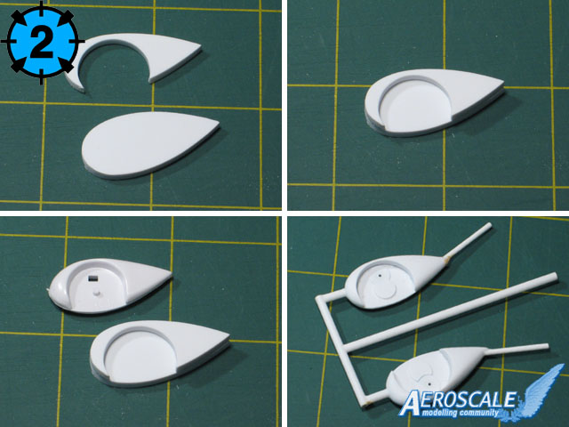
I started with a scaled-up drawing of the fairings, of which I cut out and glued to some 1/8 styrene. I cut two blanks for each fairing, as it would require a sandwich construction, much like the original kit part. On the outer blank, I ground out the wheel well with my rotary tool. In picture 2 we see the two pieces, ready to be glued together.Once I finished shaping and sanding them, I was smiling like a circus clown. It was then that the little voice took over. Hey Mark. Why not make copies, in case you ever wanna build another one of these? Thank you Little Voice. Not a bad suggestion. I glued the two farings to a quickly constructed styrene rod tree. This is now a pattern for resin casting
Ok, I got the groovy farings. But now, I needed wheels. The kit wheels are too small, so once again, Id have to manufacture my own wheels. The next photos (picture 3) show the steps. Again, I got some 1/8 styrene, and a circle template. I drew out the diameter, and drilled a hole through the center. I made angled cuts around the circle with a razor saw until I had a hub roughly the shape of a stop sign. Next, I mount it on my rotary tool, and hold a sanding block to its edge. Shazam! An octagon is now a circle!
In picture 3 you can also see the three main components for the wheels: The styrene hub, a center cap, made with .010 thick styrene and a 1/8 hole paper punch, and a rubber O-ring for the tire. Next, we assemble the parts. This is now our casting blank (also called a buck).
Since the O-ring wasnt really wide enough to suit my taste, I widened it. How? First, I cast an open face silicone mold, then I cast two copies, pouring up to roughly the center of the O-ring. Once hardened, I sanded the backside of both castings, then glued the backsides together. But first, I inserted a thin styrene disc between the two wheel faces. This built up the necessary width. Lastly, the side of the wheel that was to be mounted to the faring was sanded slightly flat. Now that I was satisfied with my master wheel, I made a quick mold from it, then cast an entire wheel.
Making the silicone molds
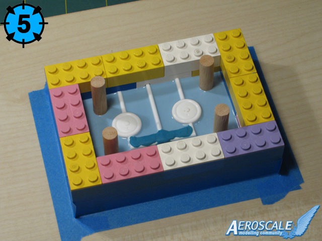
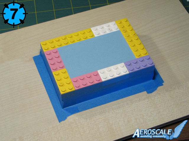
Now that I had two wheels, I could make my pattern, and glue it up to a tree. Photo 4 shows the tree in a mold box, assembled from Lego blocks. One block has a hole drilled through horizontally, which suspends my pattern at a perfect horizontal angle. Notice the four dowel pins in the corners. These will key the mold halves, and are held to the backing board with a drop of white glue. Dont use anything stronger, because youll need to remove the dowels before you pour the second half of your mold.Photos 4 to 8 shows the two-piece RTV silicone mold I casted, following steps outlined in the article in the May 2005 issue of Fine Scale Modeler magazine.
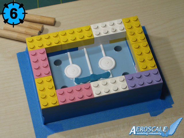
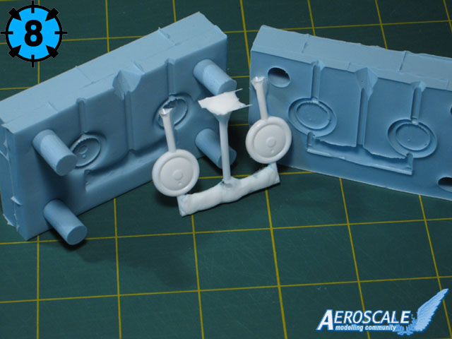
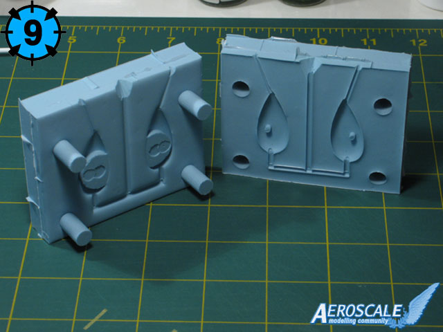
The first half is poured up to the halfway point on your pattern (picture 5). After four hours, it will be dry. Now wiggle the dowels loose and remove them (picture 6). Spray the exposed portions with a mold release agent, then pour your second half up to the top (picture 7). The release agent is critical. Without it, your pattern will be permanently entombed in silicone. In another four hours, youll be ready to cast your wheels. Whammo, baby! A miracle of modern science! This keying method with dowels works so well, you shouldnt need anything to hold your mold halves together (picture 8 and 9). They will fit and align together extremely well, and will remain tightly locked together until you take them apart.
In picture 10 you can see the wheel fairings pattern, next to the cast resin duplicate. Pretty spiff, eh?
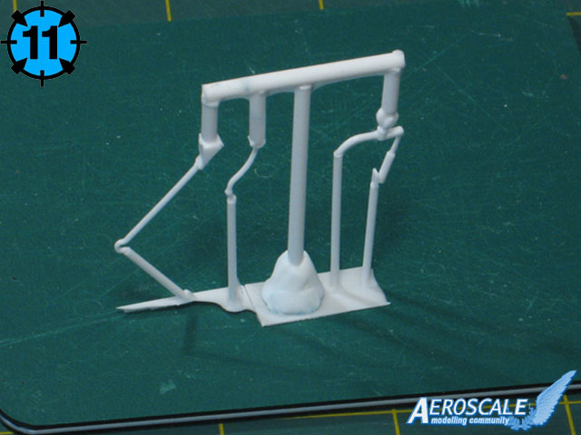
Picture 11 shows that I have also duplicated in resin some of the smaller items, such as the tailwheel, the control column and the tailhook, which I scratchbuilt earlier. At this point, and after all of my R & D, it is very possible that I will be offering an update parts set for this miserable Lindberg kit, so that the other two people in the whole world who own this kit can have the same fun with it as Im having. The update set should be including all the parts you see here, as well as a complete cockpit, a new cowl, an exhaust ring, and a vacuum-formed canopy (windshield, in this case. More on the vaccuum-formed items in the next installment.). Possibly decals, too. No promises, though!
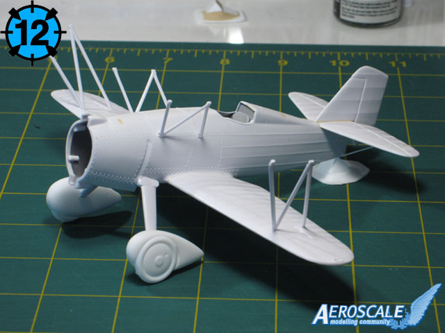
Finally heres a shot of the plane with the new resin farings attached, and the wheels setting in there for example (picture 12).
Conclusion
What have I learned so far? I learned that Im not a half bad machinist (if I can be allowed to pat myself on the back!). I learned that I can take a plan for a part that is largely laid out in my head and turn it into a physical, tangeable representation. I learned how to make molds and resin castings. This is stuff I never would have bothered with if I only stuck with the high-dollar kits. And if an utter, blithering knothead like me can do this stuff with a small measure of success, then cartainly a normal, intelligent person like you can, too!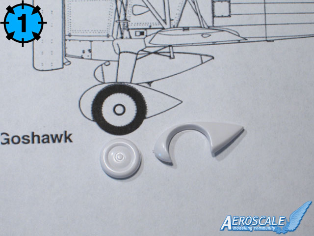


About the Author


FROM: CALIFORNIA, UNITED STATES
Just a modeling enthusiast, who also dabbles in 3D-CAD, resin casting, and 3D printing.
Comments

Hi Matt
many thanks for the hints!! Hope i remember them until the next time I try the stuff myself ...
best wishes
Steffen
JUN 08, 2007 - 09:47 PM

A good, very understandable article, Mark, nice job, and thanks for the effort, mate...as Jean-Luc has said, hope it's not the last!
Cheers,
~Gunny
JUN 08, 2007 - 10:17 PM


Very nice article, well done.
For lego leakage just tape or foil the inside and there isn't any.
I know with the RTV mold I use the length of your allignment rods would not last more than a few pours. I would opt for shorter rods - just a personal deal for me.
JUN 08, 2007 - 11:01 PM


What is that Steffen? [/quote]
Me thinks he is just trying to pester (bug) someone named Atti.
Mark, excellent article! Super subject! I hope you are archiving the building of the FC. Showing how to bring one of these old kits from 'also-ran manufacturers' to museum quality is a good way to inspire and encourage.
I, too, hope to see more from you.
JUN 10, 2007 - 03:00 AM

Thanks for spending the time to put this article together. It is very helpful. I have always wanted to know how to do this and you walked through a succinct and clear process to do it. Thanks.
Marty
JUN 12, 2007 - 03:05 AM

Folks
New to the site having trawled the web to find out how to make molds and cast items in resin. Came across Mark Bulcher's excellent article and am ready to try it out. However, there are a couple of questions that I need answered (Possibly silly questions to some!) but having not tried this casting lark before I wish not to make the mistakes that those before me have made and to get the best results that I can.
What is "RTV" abbreviated for in "RTV Silicone"?
What type of resin is used in Marks article to produce the quality of detail in his castings as there are numerous types of resins on the market?
(I note some of the other replies mention different types of resin but I am non the wiser at present).
Require three chimneys for a model building and, having crafted one, I do not have the will nor time to constuct two more. Casting seems to be the sensible approch to take to get all three looking the same.
JUL 04, 2007 - 09:26 AM

Greetings, and welcome to Aeroscale!
RTV is short for Room Temperature Vulcanizing, people much smarter than I will have to answer the rest of your questions.
JUL 04, 2007 - 09:52 AM

Steffen-
My apologies for not addressing your questions sooner. As a relatively new forum user, I had no idea there was a discussion group attached to an article. This site never ceases to amaze !
1. The Lego blocks fit fairly snugly, but there will indeed be areas that will leak slightly. That is why I wrap the outside of the Lego form with low-tack masking tape, and again at the bottom edges so nothing leaks out the bottom end.
2. The "sprue" method was utilized for two reasons: first, because there's less clean-up time on the wheel (less excess resin to remove from the wheel), and second, it is far easier to remove a cast part from a two-piece mold than from a one-piece mold, and as such, your mold will not tear from stress, like a one-pice mold can do. Another benefit is that you can cast several pieces at once if they're on a sprue, this is much more difficult with a one-piece mold. Try it, it's really not that complicated. You just have to be sure your parts are aligned on center with your pour spout and breather tubes, so your mold halves don't encompass any one attribute of the sprue.
The resin I use is available from MicroMark (www.micromark.com), it is their CR-600 High Performance Casting Resin. It has the pour consistency of water when fresh, and then to a light maple syrup about 4 - 5 minutes later.
Best regards-
Mark
JUL 17, 2007 - 05:22 PM
Copyright ©2021 by Mark Buchler. Images also by copyright holder unless otherwise noted. The views and opinions expressed herein are solely the views and opinions of the authors and/or contributors to this Web site and do not necessarily represent the views and/or opinions of AeroScale, KitMaker Network, or Silver Star Enterrpises. Images also by copyright holder unless otherwise noted. Opinions expressed are those of the author(s) and not necessarily those of AeroScale. All rights reserved. Originally published on: 2007-06-09 00:00:00. Unique Reads: 27111

WEB HOSTING BY


Copyright ©2021 AeroScale and Kitmaker Network, a subsidiary of Silver Star Enterprises
All Rights Reserved. Please read our Conditions of Use and Privacy Policy.
All Rights Reserved. Please read our Conditions of Use and Privacy Policy.