The brain child of H. P. Folland and Major Frank Widenham Goodden, the SE 5 airframe was modified after the initial batch of 24 (A4845 - A4868.) It was in the middle of the second production batch (A8898 - A8947) that design alterations created the new designation SE 5a. Essentially shortened wings and revised aileron controls were incorporated. In the matter of aircraft nomenclature it is of interest to note that the annotation of the Royal Aircraft Factory drawings states that it was modifications to the mainplane that distinguished the SE 5a from the SE 5. But in the Air Board technical notes are headed; (I) SE 5a, 200hp Hispano - Suiza (II) SE 5, 150hp Hispano - Suiza. The first production SE 5a was A8923.
The model
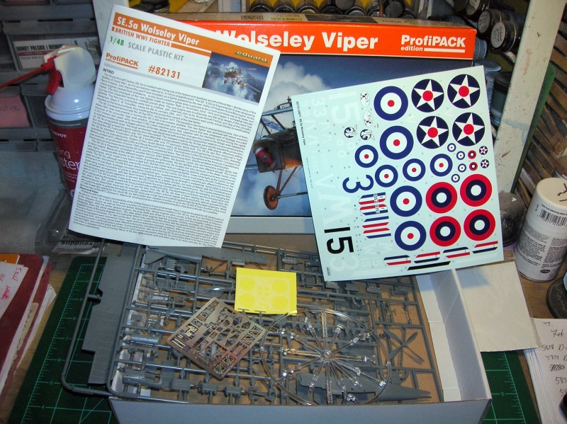
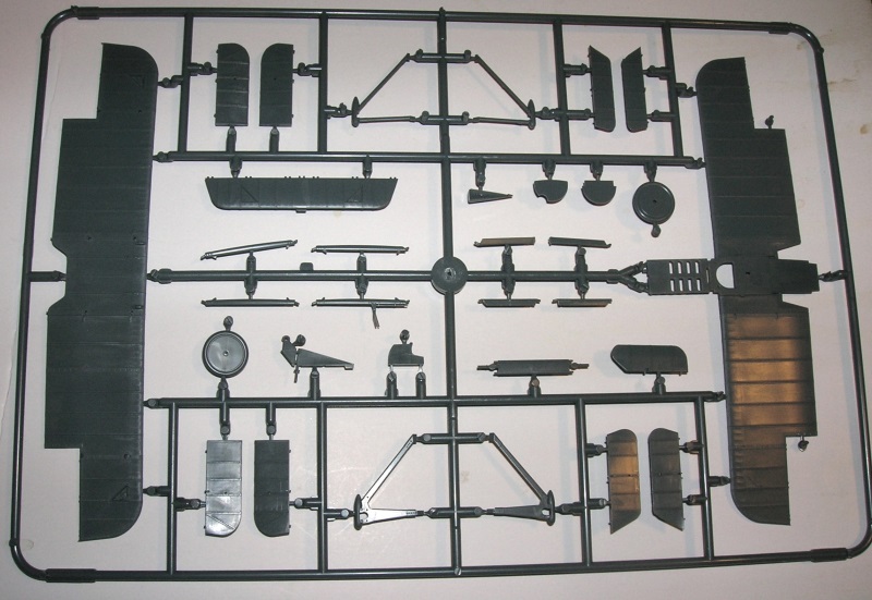
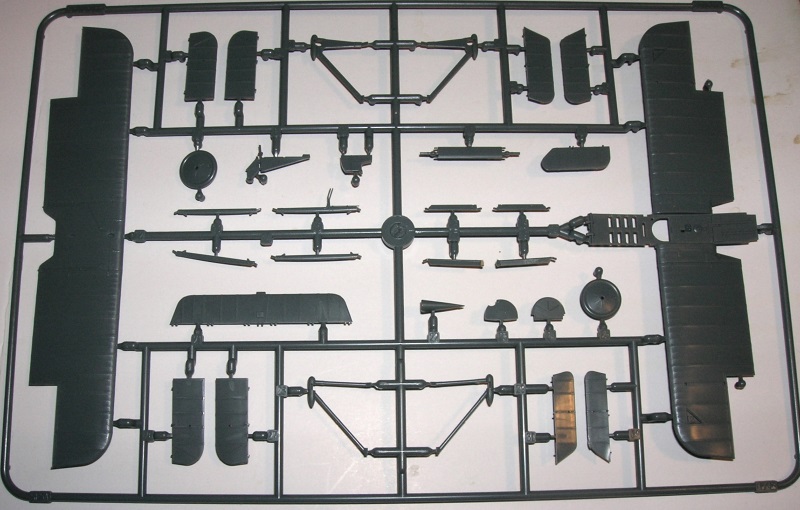
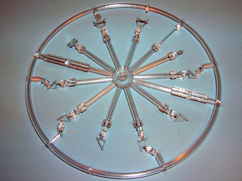
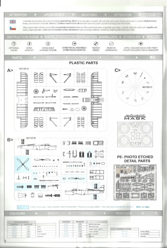
As a model the SE 5a has been a favorite subject for many years. Now in March 2017, the Eduard 1/48 kit 117 plastic piece version arrives. This kit is like all Eduard WWI aviation kits in that it does have the full engine present. The over all subtle detail contributes greatly to the over-all look. First if you want to rig this kit, you should plot all the rigging lines and strut locator holes you will need to work with. Planning ahead using references and plan views will ensure your success. Pre-drill all pilot holes for each end of the struts and the rigging wires. Do take notes. There should be two holes for each wire and each strut. Drill the strut locator holes and note that sometimes a strut may share the same hole as another intersecting strut.
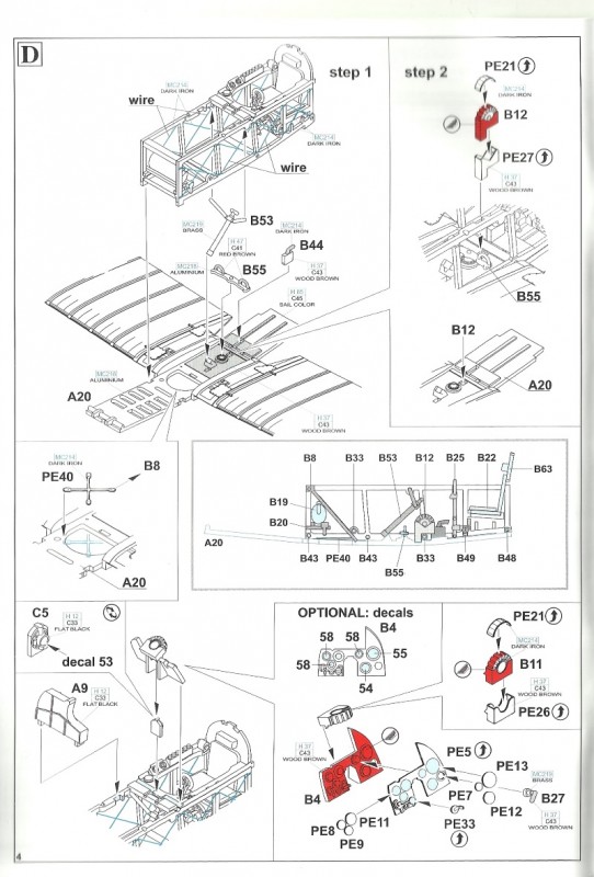
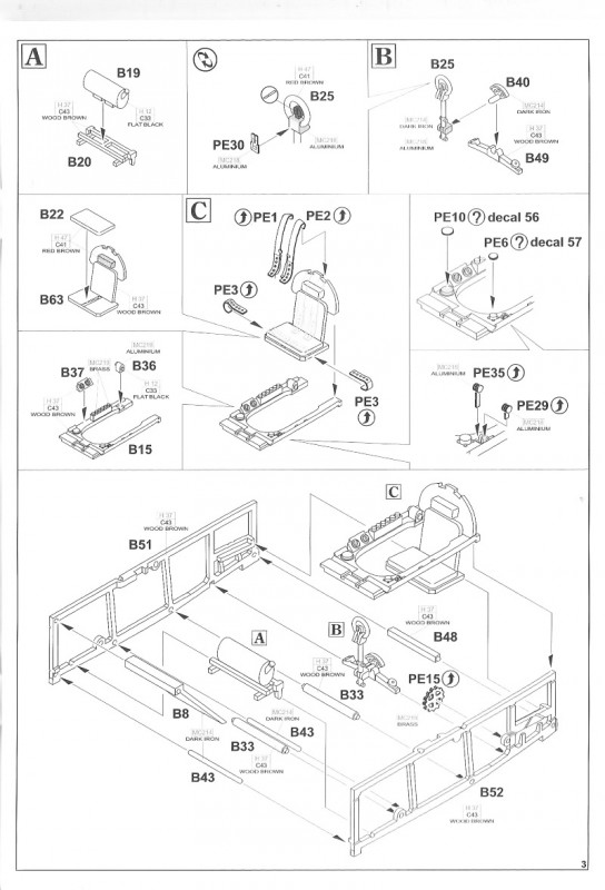
Step A. Oil Tank (B 19) and support (B 20) assembly.
Step B. Next the control column (B 25) can have the PE triggers (PE 30) added to replace the plastic items. Then add the aileron actuation pivot (B 40) and column lower brace (B 24).
Step C. The seat (B 22 & 63) represents a leather padded version. The lap (PE 3 X 2) and shoulder (PE 1 & 2) harness is typical for factory installed items. Note; the alternative wide lap belts were usually changed at the unit level per the pilots choice. On the support shelf (B 15) at right you have the inclinometer (PE 10 or decal 56), twin magneto switches (B 37) and a flare rack. On the left side of the shelf (B 15) you have an optional fuel gauge (PE 6 or decal 57) not seen on all examples and (PE 29 & 35) throttle levers for fuel and air pump advance /reduction.
The oil tank assembly, baffle / deflector plate (B 8) is added to the fuselage (B 51 & 52) and will be ultimately placed over the lower fuselage cutout in a raised 45 degree attitude. The lower cross braces (B 33 X 2, 43 & 48) and the seat and shelf assemblies complete the structure. The wheel (PE 15) for the adjustable tail incidence is also included here.
Step D. Next, the center of the lower wing (A 20) serves as the foundation for the cockpit internal structure from step C. Eduard recommends you add crisscross wires to simulate bracing. The you are to add the synchronizer lube tube (B 53), rudder bar (B 55)and flare gun storage box (B44). The floor mounted Lewis gun drum storage (B 12) can be augmented with PE (PE 21 & 27) details. Eduard recommends you add crisscross bracing to the open area of the lower fuselage cutout in A 20. The instrument panel comes in plastic (B 4) or in PE (PE5) with PE gauge faces (PE 7,8, 9, 11, 12 & 13) or the faces in decal form (54, 55 & 58 X 3), type 5/17 compass ( C 5 & decal 53). While the structures are made of varnished wood the gauge faces are mostly black with white characters. On the right side of the compass you have the oil pressure, tachometer, air speed and fuel tank hand operated air pump (B 27). On the left you have the brass fuel selector dial, radiator thermostat, air pressure gauges. The Vickers ammunition storage bin (A 9) is added here as well.
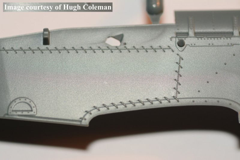
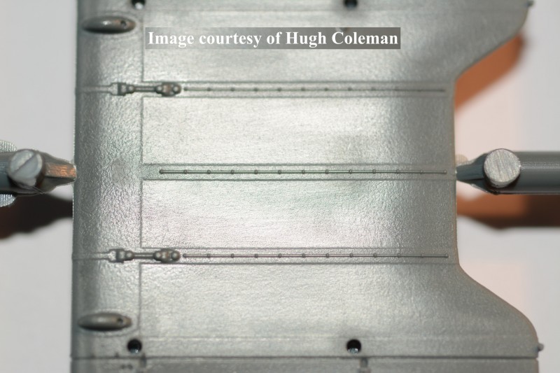
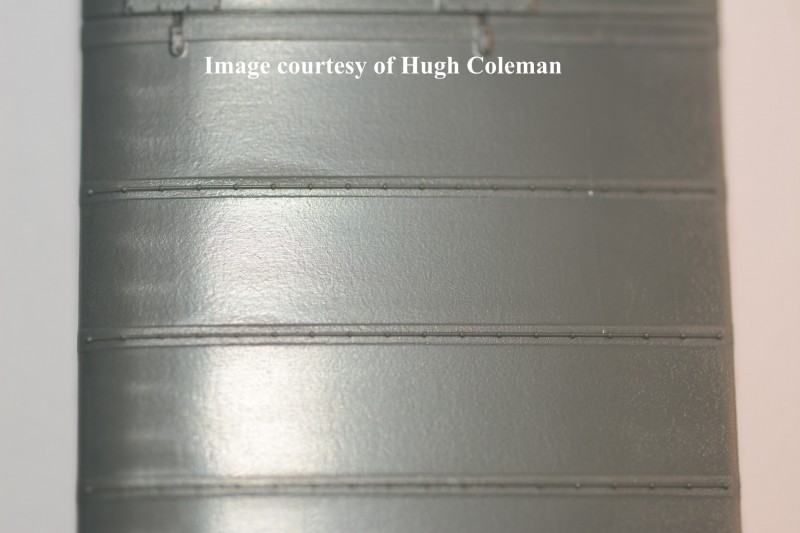
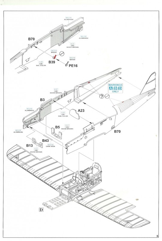
Page 5. Note the pilots left fuselage side (B 70) has a spark advance lever (B 39 or PE 16) attached. On the pilots right fuselage side (B 3) Eduard has you adding the engine supports (B 5 & 13) and a cross brace rod (B 43). The fuel cell here is represented by a single rear facade face (A 23). Note, the moldings on the outside of the fuselage are very well done and almost to scale. The thread used for lacing is much heavier than rib stitching thread.
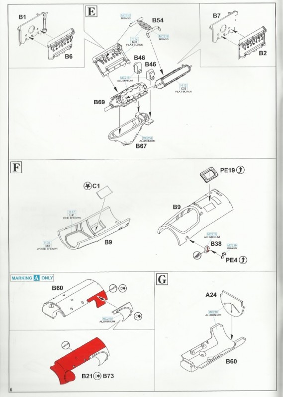
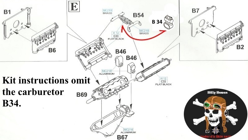
Step E. This assembles the Wolseley Viper. The cylinder banks are assembled in halves (B1, 2, 6 &7). Be sure the 4 portholes are on the outside faces for the exhaust pipes. Also engine parts are the carburetor (B 34 & 54), magnetos (B 46 X 2) and crankcase (B67 & 69). B 34 was omitted from the kit instructions but can be viewed in the on-line Pdf. Note Eduard has also provided the parts for the 200hp Hispano Suiza motor. But the way it is designed you can only completely build one or the other from the kit.
Step F. Shows the internal applications of the kit upper forward fuselage deck (B 9) and clear window ( C 1) to allow sunlight to illuminate the instrument panel on the original machine. There is also the outside framing (PE 19). Also you add the external Magneto crank (B 38 or PE 4).
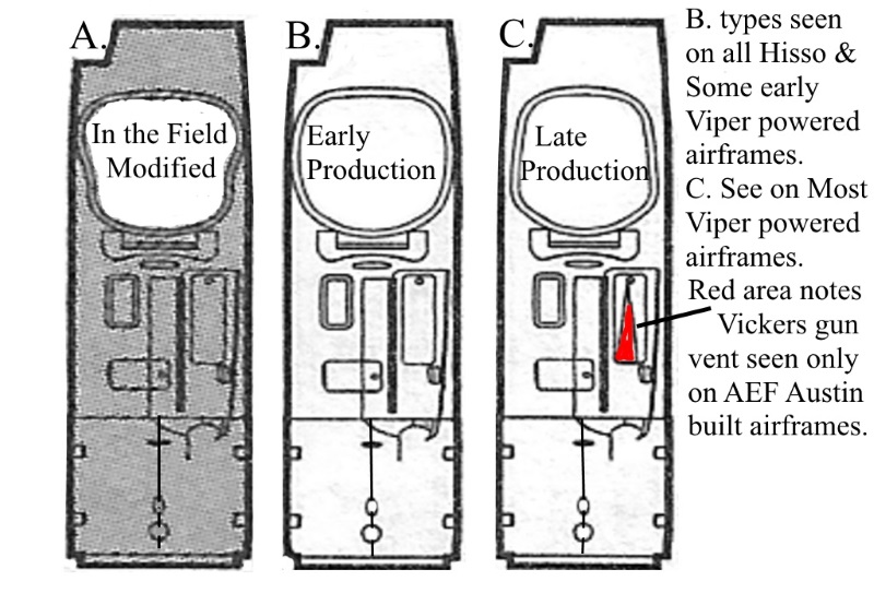
Note: Eduard cut some corners here and only provided one example (the British standard for the SE 5a type) of the 3 possible types of the upper forward deck for the different cockpit cutouts. They omitted the early production wider open type seen on the Hisso powered and some early Viper powered SE 5a airframes. Also there is an cut down example of the in-the-field modification to give the pilot more shoulder room. A nice 4th addition would have been to include the bulged cockpit version that was the first attempt to add shoulder area for the pilot. In each example the cockpit cutout is different in profile.
Eduard asks you to modify the kit engine cover / bonnet (B 60) to match an early Viper installation for C.1096. Otherwise B 60 is used unmodified on the late Viper profiles.
Step G. Here add the forward facade for the fuel cell (A 24) is added.
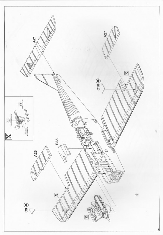
Step X. Is shown as an inset on page 7 and details the pulley inspection windows. Page 7 also brings together the fuselage (B 3 & 70) lower wing (A 20) and engine assemblies. Then you add lower wing ailerons (A 26 & 27), next the fuselage cover for the fuel cell (B 65) and horizontal tail unit stabilizer (A 21).
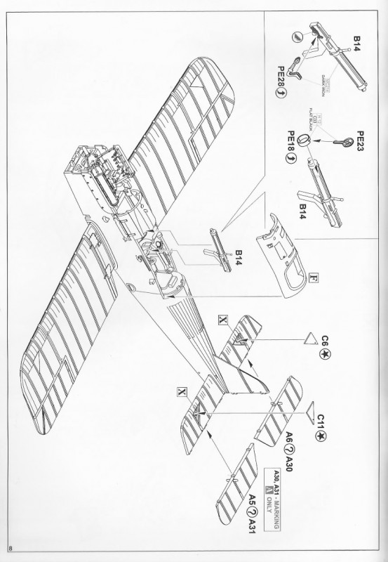
Page 8. Continues and details to the basic build. The Vickers machine gun (B 14 & PE 18, 23 & 28). Then the cockpit cutout deck is useful only for the British SE 5a. Note, there are two types of elevators ( A 5 & 6 or 30 & 31) depending on which profile you choose to do. You also can apply the clear inspection windows ( C 6 & 11) for the cable pulleys.
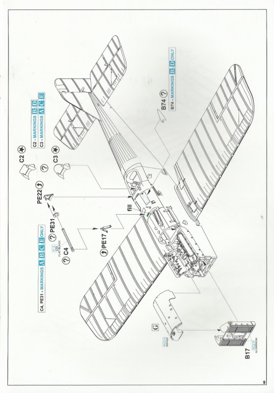
Page 9. The radiator (B 17 ) is the typical twin block version seen on all factory installed 220hp Wolseley Viper installations. Now, Eduard has a Brassin (648 298) set to be a drop-in replacement for the kit item. The engine cover / bonnet from Step G is added here as well. But many may want to show off the kit motor. Now that is an item there should have a small PE fret. 4 wiring harness, smaller tubing in the front of the cylinder banks, linkage and etc. If you are building an AEF Austin built example then you will want to add the Vickers machine gun vent (B 74). On the upper deck in front of the cockpit you add the Aldis optical scope ( C 4 & PE 17, 22 and maybe 31) The windscreen and framing comes in two types ( C 2 or 3). I would add the wind screen later.
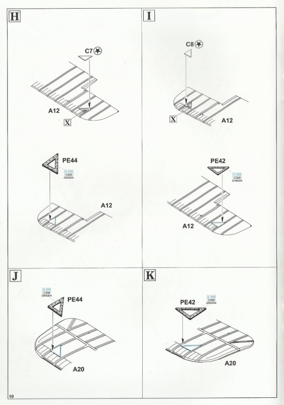
Step H & I. Lower surface upper wing (A 12) cutouts for the cable pulley inspection clear covers ( C 7 & 8) and the PE framing (PE 42 & 44) left & right. Note these item will not be out of scale compared to the originals. See step X.
Step J & K. Upper surface of the lower wing (A 20) cutouts for the cable pulley inspection clear covers ( C 7 & 8) and the PE framing (PE 42 & 44) left & right. Note these item will not be out of scale compared to the originals. See step X. Old friend and modeler Hugh Coleman commented. . . .On an SE5a, the stitch was knotted at on the top of the rib, then the thread laid lengthwise along the rib to the next stitch and knot. There was no knot underneath the wing and no thread lengthwise along the rib... Eduard should NOT be trying to replicate this detail on the underside of the wing. If anything, there should be a very fine hump for the stitch itself under the doped rip tape. . .
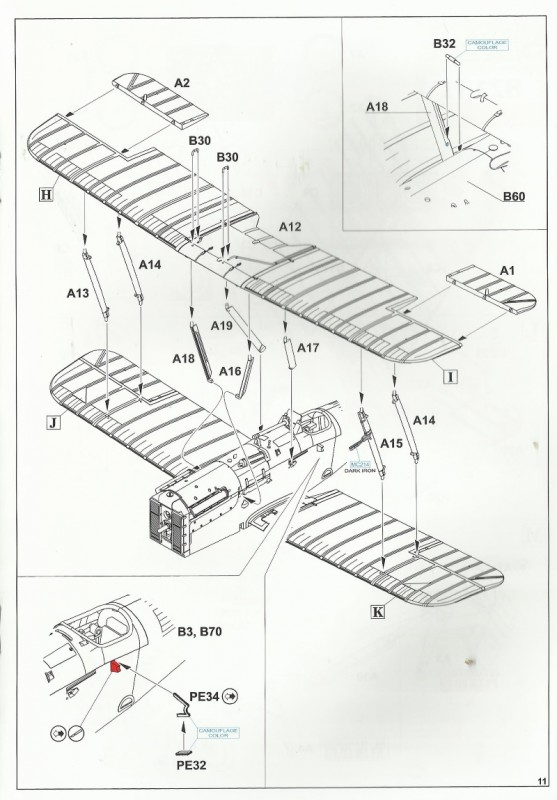
Page 11. Adds top wing (A 12), interplane (A 13 & 15) (A 14 X 2) and cabane struts (A 16-19). The battle-cry of the neophyte modeler - I cant do that, it has all those struts! Several methods are used with struts. I will either replace kit items with modified brass sections or put brass rod in all the ends of the kit struts. This reinforces your work but also gives your struts an adjustable (by bending) pivot that works to your advantage, especially when your kit has dihedral, reverse or forward stagger (like the SE 5 and SE 5a types.) When you have all strut locator holes in the right places and the cabane struts are fixed at the right angles, everything else should go great.
In this case I will use the kit provided struts. Now with all of the struts in-place and all rigging holes are found to be open and ready to take the strands begin your rigging. The key to working with monofilament is start by securing all of the strands that go into the anchoring holes first. Note Eduard has some after market PE brass called Stretchers set # 48915 that will help to keep the twin RAF wires at the right distance apart. This usually begins with the top wing areas adjacent to the cabane and interplane struts. But on the SE 5a there are two pairs of RAF wires near each lower wing root. You want to start here and with the top wing areas adjacent to the cabane and interplane struts. You can use an accelerator to dry the glue quicker but this must be managed carefully (most of theses are known carcinogens.} Normally I just take my time to ensure the anchored strands are completely dry. Start with the loose ends of the fuselage anchored rigging near the cabane struts and move out and across to the interplane struts. Once the anchored strands have the loose ends inserted through the corresponding holes (that you pre-drilled) near the interplane struts, use spring action wooden clothes pins to clip on these ends hanging under the lower wing. Attach one clothes pin for one strand with the wooden clothes pins suspended away from the model, their free weight pulling the strands tight. Then you just put one drop of thin type super glue in the hole and let thoroughly dry. Dont use metal hemostats on the small 5-8 mil as they can over stress strands and after your complete it will go slack and heat application wont tighten it permanently. When your finished rigging use a sharp #11 blade and clip all ends of the secured strands and then carefully scrape any glue spots from the bare plastic / resin. Now finish these surfaces to suite your chosen profile. NOTE!!! When you are scraping away extra glue be sure to hold the wing specifically that you are working with. If you are holding the bottom wing and working on the top, it will cause undo stress and damage the connections for the struts and rigging.
The ailerons (A 1 &2) are added, note the correct angle for each (like the ones on the lower wing from page 7. Eduard also offers PE exhaust hangers (PE 32 X, 34 X 2). There is also a small plastic item to represent the short segment of plumbing (B 32). The radiator overflow plumbing ran from the radiator header to the right front cabane strut up the strut to the bowl on the bottom of the leading edge radiator expansion tank.
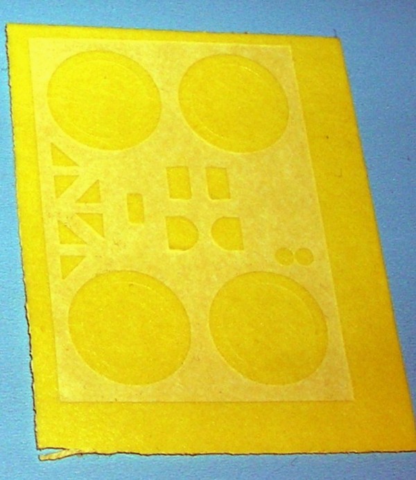
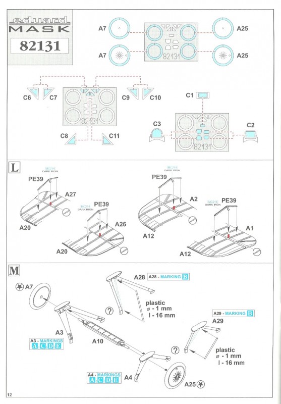
Page 12. At the top of the page you have diagrams for the Eduard express masks for this kit.
Step L. Next you add the PE actuation horns and their cable segments (PE 39 X 4) to the wing tips.
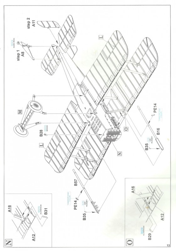
Step M. The landing gear legs come in two variations. Both are the late types, wooden faired, steel tube versions (A3 & 25) or plain three legged steel tube versions without the fairing (A28 & 29) with a faired axle / spreader bar (A 10). The wheels (A 7 & 25) are profiled to represent the typical 700 X 100mm tires.
Step N & O. The leading edge of the center-section was two tanks, the one on the left was auxiliary gravity fuel tank and the one on the right half was an radiator overflow expansion tank. The radiator overflow plumbing (B 29) ran from the radiator header to the right front cabane strut up the strut to the bowl on the bottom of the leading edge radiator expansion tank. (B 31) The plumbing from the bowl on the bottom of the auxiliary gravity tank went to the left front cabane strut and to the fuel selector cocks on the instrument board then to the carburetor. Adds the exhausts (B 16, 35 X2, PE 14 X 2) and the assembled landing gear from step M. Also add the steerable tail skid (A 8) and the rudder (A 11).
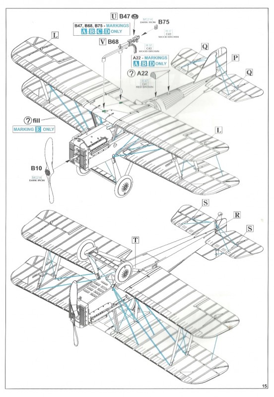
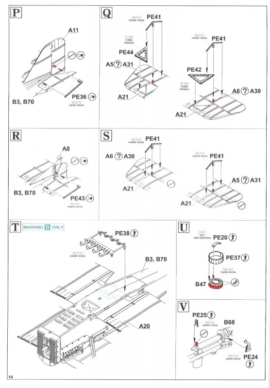
Step P - S. Next you add the PE actuation horns and their cable segments (PE 36 X 2, 43 X 2, 41 X 4 ) and framing (PE 42 & 44) left & right. Note these items will not be out of scale compared to the originals. See step X.
Step T. Here you assemble the Cooper bomb rack (PE 38) but no bombs parts are present in the kit.
Step U & V. Next the Lewis gun MK II (B 68 & 75) and the 97 round magazine (B 47, PE 20 & 37). The gun is on the Foster mount that is set up for the geared 200hp Hispano Suiza installation. To better represent the Viper Foster mount installation the front and rear posts need to be cut down. Next you can add the headrest (A 22) if your profile calls for it. Note the headrest was not on some airframes as they were sometimes removed in the field. Finally add and propellor (B 10) to finish the build. Complete your rigging here at this time.
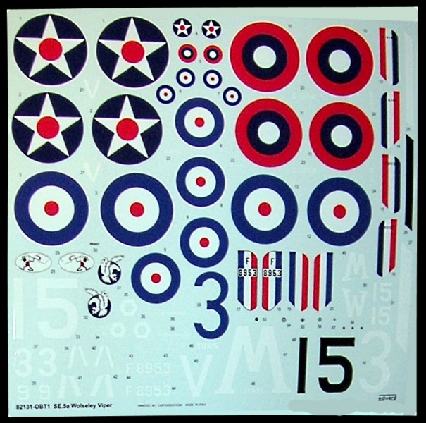
Decals;
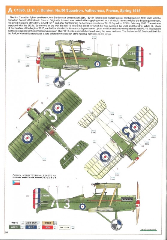
A. SE.5a Wolseley Viper C1096, flown by Lt. H.J. Burden, No. 56 Squadron, Valheureux, France, Spring 1918. There is some controversy over this profile and it appears to be a mixture of two aircraft D283 & C1096. This version appears to be based on the Memorial Flight replica. To better represent C1096 delete the word Maybe and simulate a St. Christophers medal.
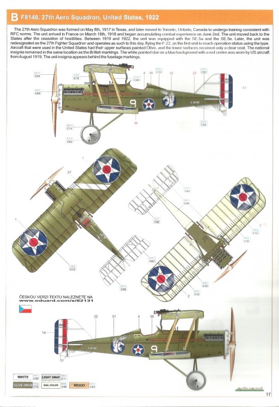
B. SE.5a Wolseley Viper F8146, 27th Aero Squadron, 1922.
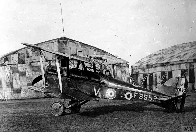
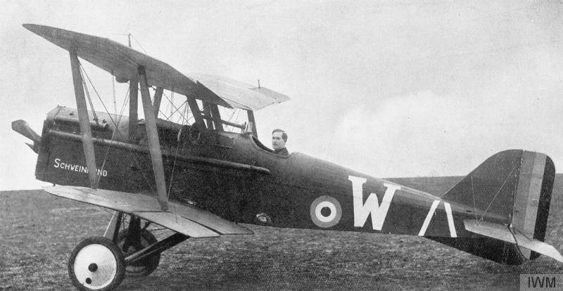
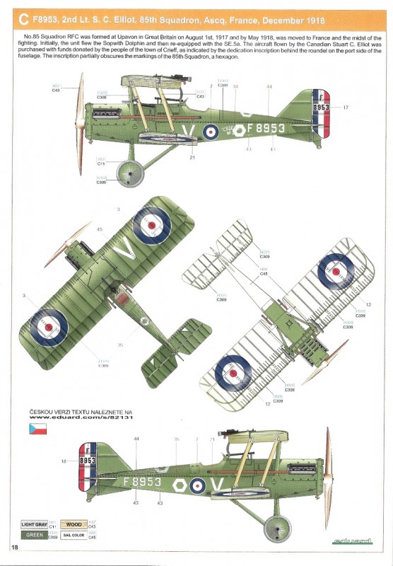
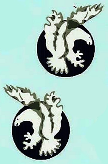
C. SE.5a Wolseley Viper F8953, flown by 2nd Lt. S.C. Elliot, No. 85 Squadron, Ascq, France, December 1918.
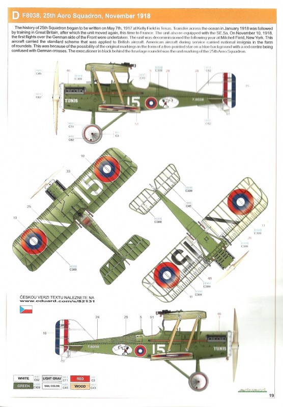
D. SE.5a Wolseley Viper F8038, 25th Aero Squadron, November 1918.
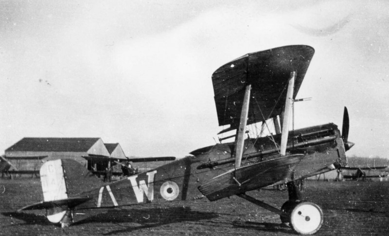
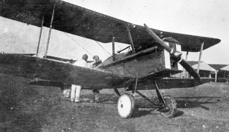
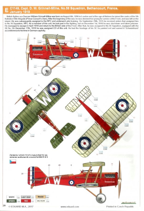
E. SE.5a Wolseley Viper C1149, flown by Cpt. D Grinnell-Milne, No. 56 Squadron, Béthencourt, France, January 1919.
References;
British Fighter Units 1917-18" by A. Revell, Osprey Pub. Ltd. 1978.
Fighting Fifty Six by A. Revell, Aeroplane Monthly Pp. 591 - 596, Nov. 1976
S.E. 5 Fighter Supreme by J.M. Bruce, Aeroplane Monthly Pp.264 - 269, May 1977
S.E. 5 Fighter Supreme by J.M. Bruce, Aeroplane Monthly Pp. 327 - 331, June 1977.
S.E. 5 Fighter Supreme by J.M. Bruce, Aeroplane Monthly Pp. 355 - 360, July 1977.
S.E. 5 Fighter Supreme by J.M. Bruce, Aeroplane Monthly Pp. 437 - 442, August 1977.
S.E. 5 Fighter Supreme by J.M. Bruce, Aeroplane Monthly Pp. 493 - 498, September 1977.
S.E. 5 Fighter Supreme by J.M. Bruce, Aeroplane Monthly Pp. 552 - 558, October 1977.
S.E. 5 Fighter Supreme by J.M. Bruce, Aeroplane Monthly Pp. 608 - 613, November 1977.
RAF SE 5a by J.M. Bruce, Datafile Special, Windsock pub.1993.
Royal Flying Corps in WWI by R. Rimell, Osprey Vintage Warbirds series #1, 1985.
The SE 5 by J.M. Bruce, Profile Publications #103, 1966.
The SE 5a by J. M. Bruce, Profile Publications #1, 1964.
SUMMARY
Highs: Great detail, complete engine, varied WWI and post war markings. Eduard has 5 aftermarket sets available for further detail. Lows: Details on both surfaces of the wing rib stitching over engineered. B34 carburetor is omitted from kit instructions - but can be seen in the online PDF.Verdict: Excellent kit well worth the cost.
About Stephen T. Lawson (JackFlash) FROM: COLORADO, UNITED STATES
I was building Off topic jet age kits at the age of 7. I remember building my first WWI kit way back in 1964-5 at the age of 8-9. Hundreds of 1/72 scale Revell and Airfix kits later my eyes started to change and I wanted to do more detail. With the advent of DML / Dragon and Eduard I sold off my ...
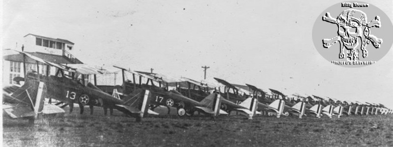
The 27th Aero line up in Texas 1920 At the far end are the unit's "captured" Fok. D.VII machines.
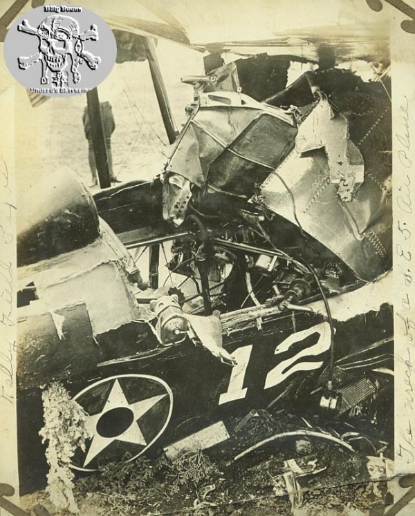
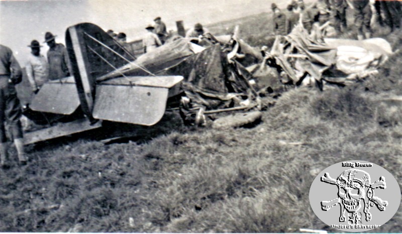
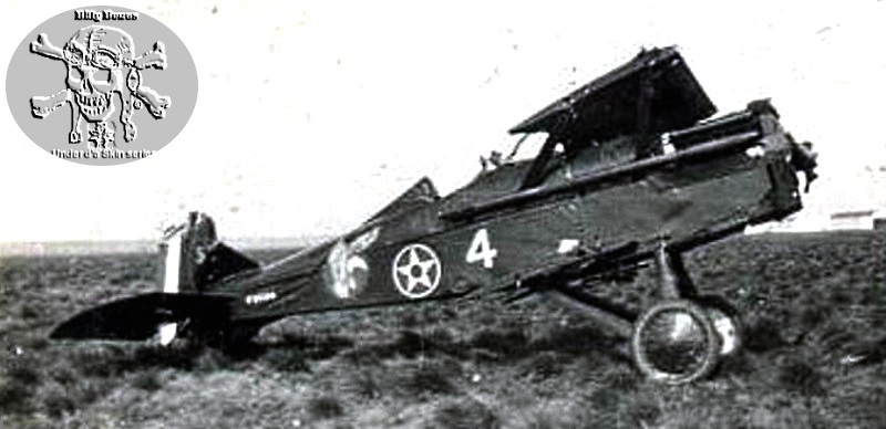
Broken 27th Aero Squadron #4 Austin built SE 5a.
Broken 27th Aero Squadron Austin built SE 5a.
SE.5a Wolseley Viper C1149, flown by Cpt. D Grinnell-Milne, No. 56 Squadron, Béthencourt, France, January 1919. Before the fuselage was over-painted red.
SE.5a Wolseley Viper C1149, flown by Cpt. D Grinnell-Milne, No. 56 Squadron, Béthencourt, France, January 1919. Before the fuselage was over-painted red.
SE.5a Wolseley Viper C1149, flown by Cpt. D Grinnell-Milne, No. 56 Squadron, Béthencourt, France, January 1919. Before the fuselage was over-painted red.
Broken 27th Aero Squadron Austin built SE 5a.
SE.5a Wolseley Viper F8953, flown by 2nd Lt. S.C. Elliot, No. 85 Squadron, Ascq, France, December 1918. Profile C in the kit
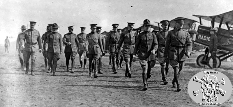
Pershing inspecting the 27th Aero in Texas 1920
25th Aero Squadron #13 Austin built F80010. If memory serves some plugger hereabouts did this scheme on a 1/32 SE 5a back in 2008.
For any confusion on the type of factory installed seatbelt applications on the SE 5a see the HGW set
Also available now in 1/48.
And this reference gives a bit more info on the early Sutton Farms types. Even though some have mentioned them - they probably were not seen on SE 5a wartime types.


Comments