

1⁄72Beriev Be-6
4
Comments
History
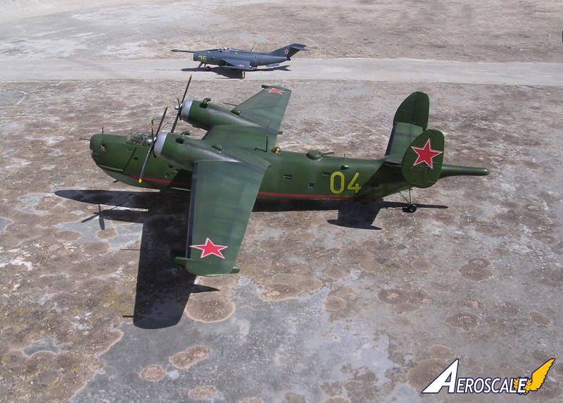
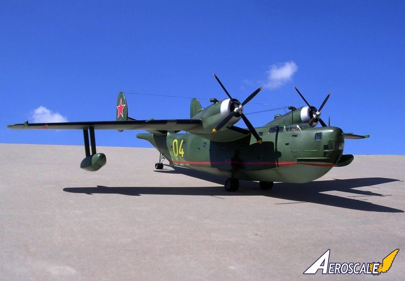
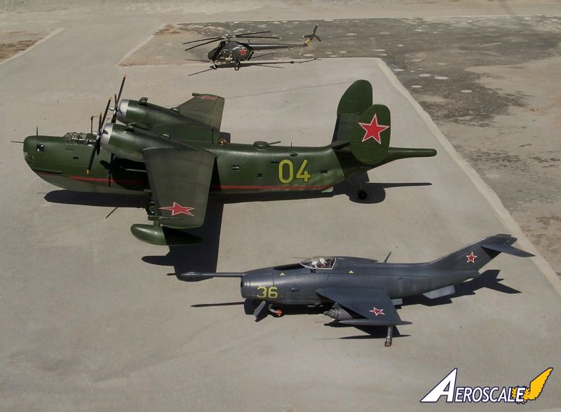
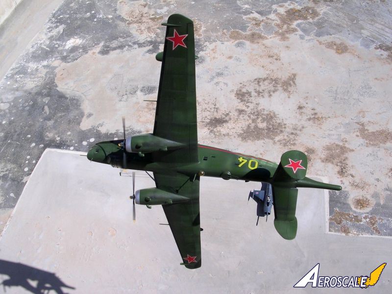
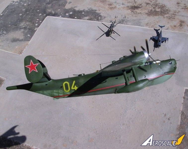
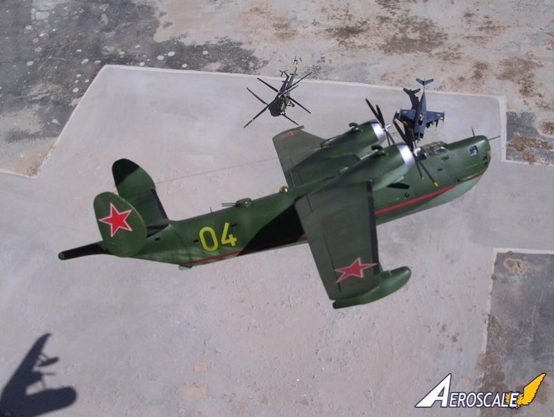
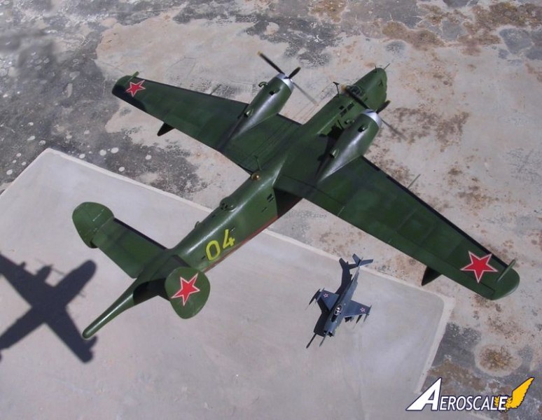
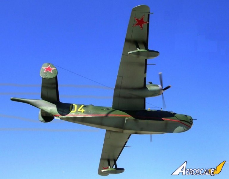
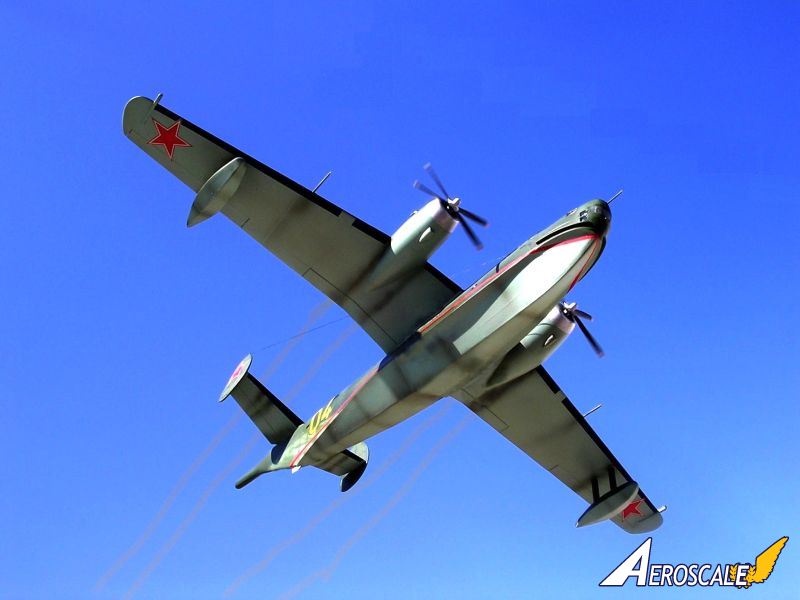
The Be-6 is a large maritime reconnaissance and bombing flying boat that flew for the first time in 1947. It was an all-metal high-wing monoplane that was powered by two 2000hp Shvetsov ASh-72 radial engines. Until early sixties it was still in service and was relegated to fishing patrol and protection duties with the Soviet Navy. It is the only Russian flying boat of post war design to have attained quantity production.The Be-6 are known to have formed part of the North Fleet since 1953 in both the rescue form that was based at Poty, and others belonging to the 318th Independent ASW Air Regiment at Donuzlav in 1967. Other Be-6s were based at the hydrobase in Taganrog. The Be-6 left a mark in the maritime history of the Soviet Union and was the forerunner to other important projects that were to come out of the Beriev line that followed. The Beriev ventured on patrol, maritime recce, ASW duties till early 70s. Others remained in service on transport or fishery protection duties into the late 70s.
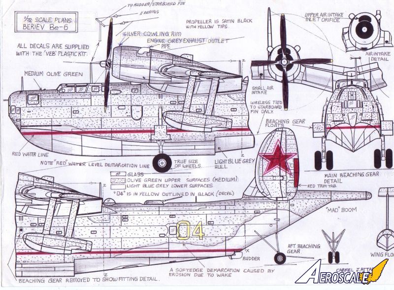
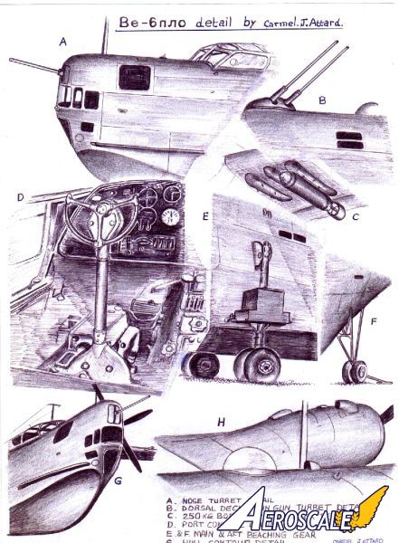
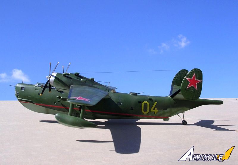
Defensive armament on the Be-6 ASW "MAD" version comprised twin NS-23, 23mm cannon in a remotely controlled dorsal barbette and a single NS-23 cannon installed in the bow turret. The Be-6 carried sophisticated equipment, which included a retractable radome aft of the second step. At a later stage it had a redesigned nose without cannon equipment. The Beriev carried a heavy offensive load comprising a variety of combinations of mines, depth charges and torpedoes on underwing pylons located outward and inward of its engines. Typical bombs carried on underwing pylons as the 250Kg bombs, shown in sketch "C". Other typical loads include AM-1000 mines, depth charges and type 45-36 ABA torpedoes.
The kit
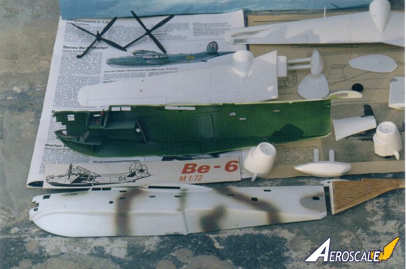
The 1:72 scale model of the Be-6 is mainly moulded in white plastic by the East German company VEB Plastikart. This is of a rather brittle type of plastic as the kit I possessed was fractured from two places in both the fuselage and main wing parts. But this is of no concern as the pieces welded together quite effectively with liquid cement. Some parts such as the propellers, tail barbette, guns, and aerial masts are molded in black plastic. These had a crude appearance and with little effort the propellers and the cannon barbette can be salvaged and used on the kit. Over the years, this kit has been released several times by other companies, most notably by Revell of Germany.I elected to do the later version of the Be-6, which was mounted with a Magnetic Anomaly Detector "MAD" "stinger" aft of its tail. This meant that the aft part of the rear fuselage had to be modified and rebuilt completely, different from that supplied with the kit. We come back to this at a later stage.
The transparencies supplied are in very clear plastic. In all there are a total of 38 components excluding the 2-part stand, which I always discard anyway. There is an assembly drawing which makes construction straight forward if one desires to do the version as issued. However in my opinion the kit was very basic and fell short of my expectations. This turned out into a project that model-wise required a lot of work to turn it into an accurate scale replica of the real flying boat. Certain areas such as the cockpit has no provision of any detail and one should not be deterred from manufacturing a cockpit floor, bulk-head, instrument panel, a couple of seats, control columns, control foot pedals and other de-tails as one desires. The ailerons, which are designed to be moveable, leave an unrealistic gap when raised or lowered so it would be best to fix these in place permanently. At the lower part of the hull there is a rectangular slot into which the stand will fit. This needs to be trimmed and filled.
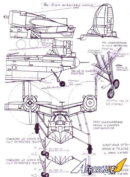
Over the years I managed to acquire copies of LETECTVI + KOSMONAUTIKA, a Czech magazine that goes back to 1980. This contained an article, which related to updating the Be-6 kit. Pages 290 and 291 produced a side elevation of the fuselage and wing plans and on pages 374 and 375 there is an accurate "stinger" MAD boom drawing. More recently more accurate material in the form of photos started to emerge and reference to these enabled me to produce accurate revised scale drawings of the undercarriage beaching gear. Adding the beaching gear to the kit produces a more impressive and realistic appearance.
Construction
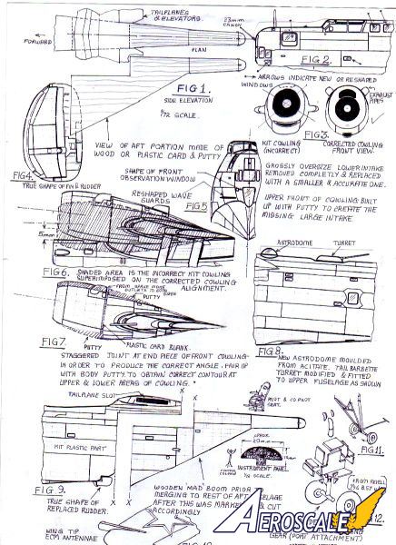
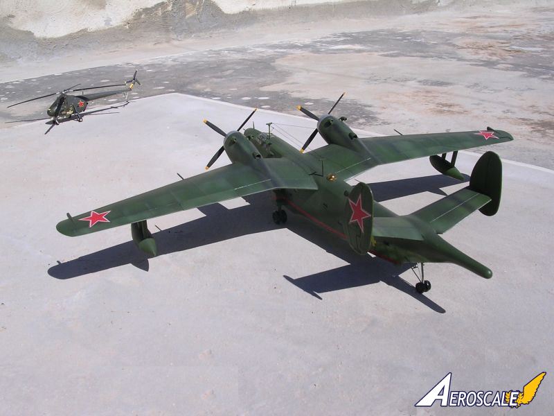
The model of my Be-6 was converted to the later version, which involved modifying the rear end of the fuselage to take the MAD Sonar equipment, which is shown in FIG. 1. Parts of the rear end of the fuselage and sonar combinations were produced out of yellow pine. This is a soft, easy to work, wood, which does not warp. Section templates were made out of cardboard using the plan and side elevation drawing in FIG.1. Producing this component took some time. In the end, after it was carved close to the shape required, it was given two coats of sanding sealer, allowed to dry and sanded down to shape.The next step was to place the fuselage halves, part I and 2 together, securing them temporarily with tape from three places. This allowed marking and cutting along line "X-X" shown in FIG.9. This was then cut with a Xacto knife and fine saw. The horizontal part was the tricky bit. This was scored several times over using a sharp modeling knife until it broke away gently from the corresponding half of the fuselage, one at a time. The end bit of the kit fuselage was discarded. A medium file brought down the desired joint preparation so that there is an even and corresponding joint between the fuselage section at "X-X" and the wooden shaped piece at "X-X" that contains the "MAD" boom.
The kit first appeared on the market over 20 years ago and was then a reasonable product. With the advent of the breakdown of the Iron Curtain certain details on military aircraft started to appear in form of photos, accurate drawings, data, etc, certain areas on the kit such as the portion ahead of the cockpit, aft of the cockpit, wave guard fairing, position of antenna masts, grossly raised panel lines, shape and size of turret/barbette needed to be looked into and each item is rectified with careful reference to the new material. Though small items these appear to be, it is surprising what improvements these will bring to the "end-product" appearance.
While the kit is still in pieces, it is important to mark, drill and shape the 15 porthole windows that are scattered throughout the length of both fuselage sides. The location of these is identified with careful reference to the 1:72 scale drawing shown. Some of the existing ones may need to be blanked over with plastic card and replaced with others of the correct shape and at the right place. At this early stage the main plane and tail plane parts are glued together and allowed to set.
Major kit faults corrected
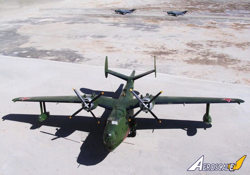
A major fault in the kit lies with the angle of the centerline of the engine cowlings with the horizontal. A quick check with FIG.6 or reference to the 1:72 scale plan side elevation will reveal the new angle of elevations. This needs to be so much inclined so that when viewed from the side, the lower part of the cowling front rim is 5mm higher than the uppermost level of the fuselage. This is illustrated clearly in FIG.6.In order to reproduce this inclination to the kit parts this has to be carried out as follows:
- (A) Remove the exhaust pipes, which are wrongly placed at the cowling joint line. The huge lower intake is also filed off completely. See FIG.3. Replacement small intake ducts and new position of exhaust pipes are needed.
- (B) Blank the rear end of the cowling (parts 14 and 15) with a 25mm round plastic card.
- (C) The upper edge of the cowling on wing (parts 3 and 4) are filed 2mm at the joint so that when parts 14 and 15 are fitted these have a corrected inclination.
- (D) With reference to FIG.7, the cowling parts are now joined together noting the new angle of inclination and also the joint is staggered by 3.5mm at the upper and lower rim of the cowling ends.
- (E) Once this has dried out, the stagger is built up with putty. This is allowed to dry, reshaped and faired over. A somewhat tedious operation but in the end it brings a satisfactory result. FIG.7 indicated the built up areas, which are shown in shaded lines.
- (F) All along the upper area of the cowling is built up with putty to produce the upper air intake, which was non-existent in the kit. FIG.3 shows the incorrect cowling front part as compared to the new one. Note also the upper area of the kit cowling that needs to be filed (shown in dotted lines) before the putty is added. This will be the lower in-take front/wall.
- (G) Having built up and reshaped the cowling, a small air intake is added to the lower cowling front as per drawing. The air intake is made out of a rear part of a small fuel tank (2 in number) found in the spares box. (e.g. AIRFIX Fiat G91 wing tanks). The upper exhaust pipes are produced from sprue, which are shaped and hollowed out at one end.
Conversion to the MAD series
Before the two fuselage halves are permanently joined, any cockpit detail as mentioned earlier is completed. Sketches show shape of pilot and cockpit seat, control 86 columns and instrument panel. I added two crewmembers as it gives a scale indication and more life to the completed model. The drawings show all the identifying features of the Be-6 to convert to "MAD" version series. This merely required cutting, filling, scribing and reshaping operations to reproduce them in model form. Vac forming of the dorsal astrodome was essential using the male/ female acetate technique. This is of a smaller diameter at the root and the hole that exists on the fuselage needs to be blanked and re-bored accordingly.The 23mm cannons shown in FIG.2 & FIG.8 are made out of 1mm diametersurgical steel needles, which are cut to the required length as to leave 12mm barrel length. Three in number are required, one for the front, and two for the dorsal barbette. The barbette was made out of "part 12" after the required alteration by blanking part of the upper slots and filing a flat top to con-form to the outline of the turret shown in FIG.8 Sketches A and B depicts enlarged details of the cannons. After the kit is completely assembled, with the major components put together, the various aerial masts and small intake scoops on the fuselage are added and the joint lines of the rear modification components are sanded, refilled and sanded gently until a smooth satisfactory finish is obtained. The two supporting struts of the floats needs thinning down their sections when viewed from front as per wing float scale drawing.
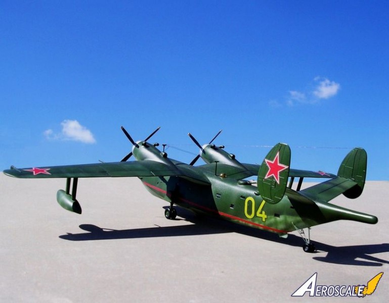
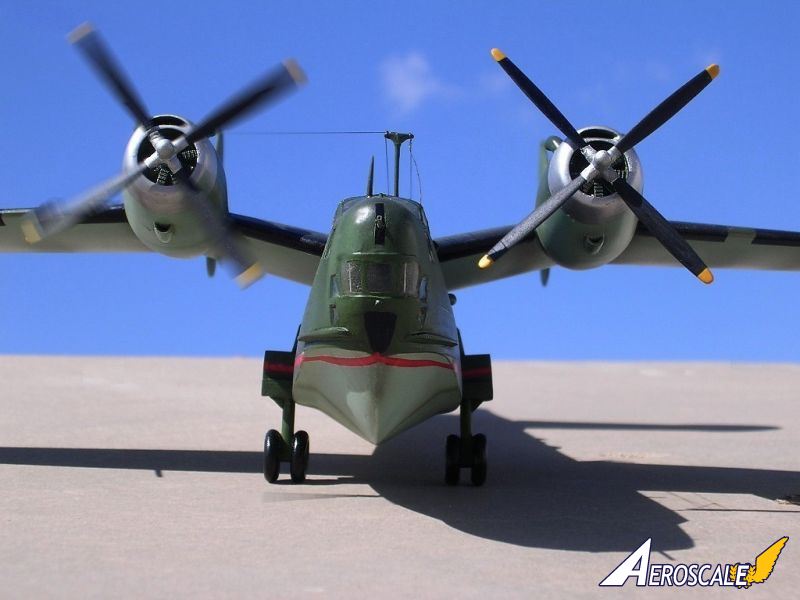
The hull rudder supplied is replaced with one from plastic card and correct outline and relocated aft of the hull structure as shown. FIG.5 shows the reshaped wave deflectors/guards. This is done by reducing the oversize ones integrally molded on the fuselage front, and also by thinning down this section with a scraper running down the remaining length. An observers front nose window is added to conform to FIG.5 and the scale plans. Wingtip ECM antennae are added - see FIG. 10. These are made from 2mm thick by 3.5mm wide plastic card, which protrudes 6mm ahead of the leading edge.
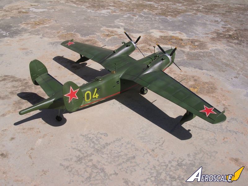
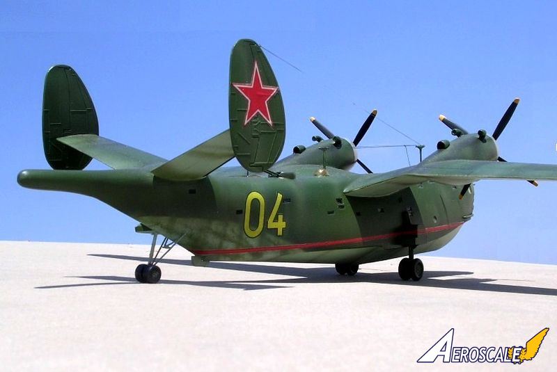
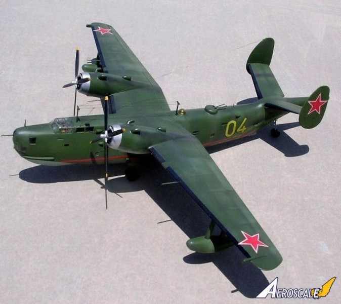
Having done all the extra work to improve the kit, then building up the beaching gear becomes imperative. The scale drawings show the correct size of the details to produce the beaching gear and FIG. 11 depicts an exploded view of the aft wheels construction; FIG. 71 shows the main wheel beaching gear along with parts to form the floats. These are made out of sprue and plastic card. Two wheels, 14mm diameter and 5mm wide are attached to the assembled structure on each side. The smaller rear wheels are 8.5mm diameter and 3mm wide. I found that for the main wheels, those coming from 1:96 scale REVELL B-57 Canberra kit are most suited, failing this, one can produce a single accurate wheel and cast 3 more out of resin using two part core and drag mould technique. The kit provides one leading edge aerial antenna. The location is correct but the aerial mast was discarded and replaced with one made from a pin. This is repeated to the other wing as most of the photos I have seen carried one antenna on each wing.
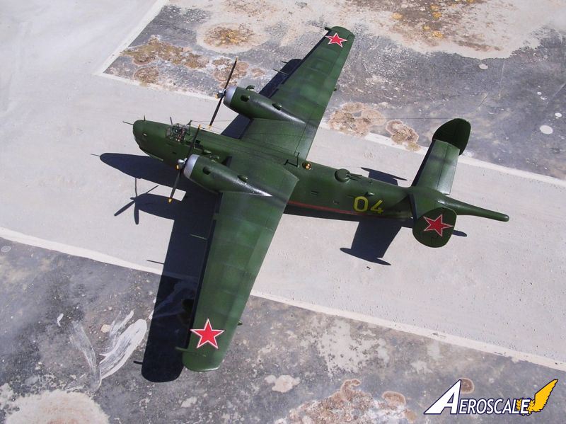
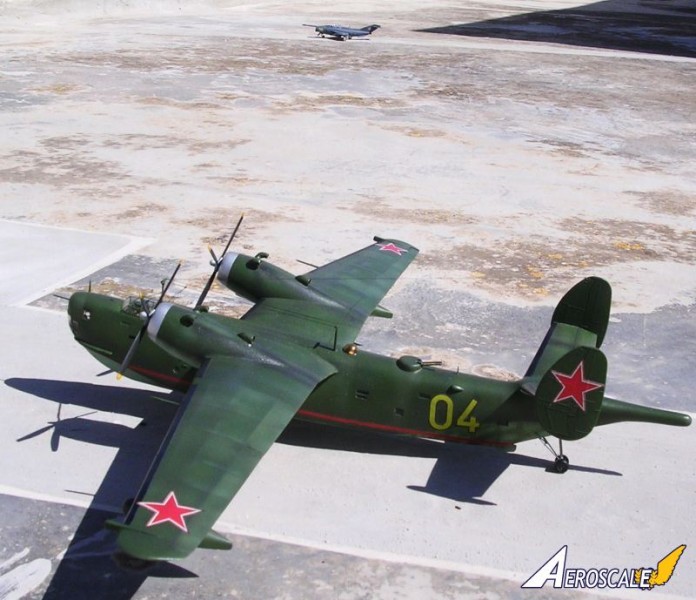
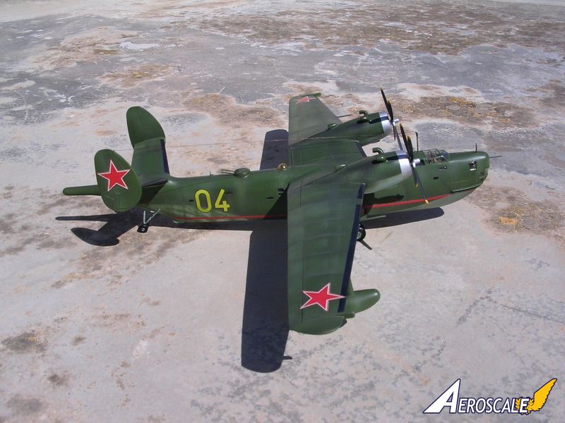
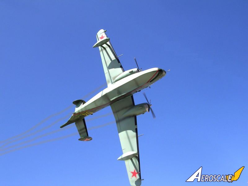
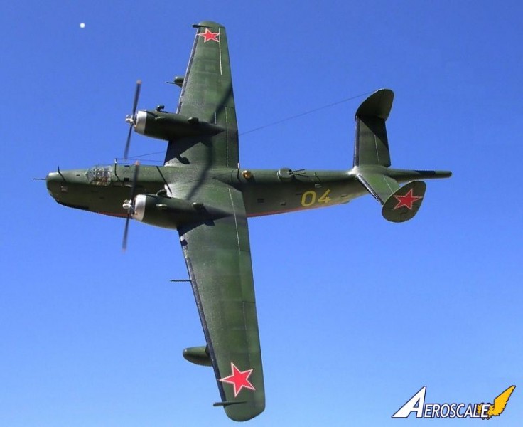
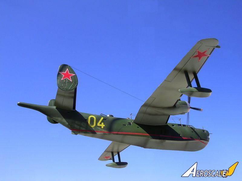
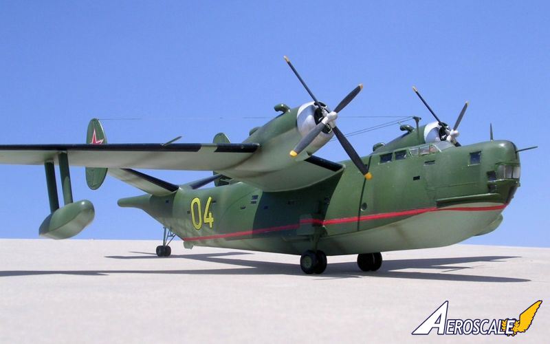
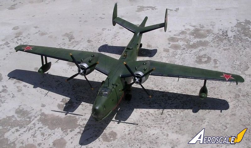
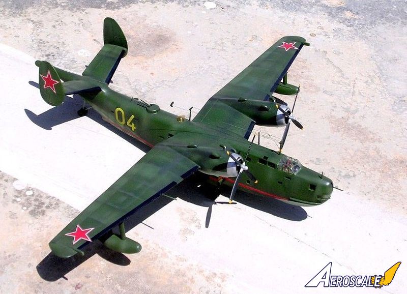
Colour and markings
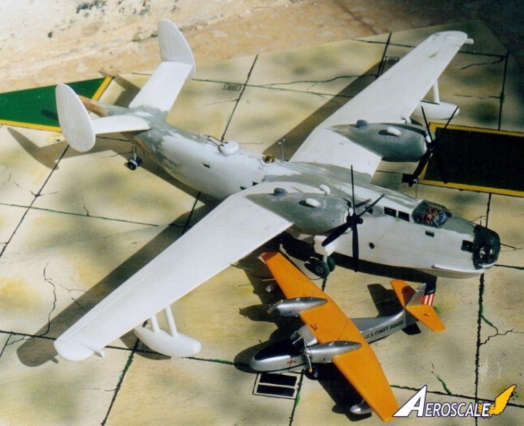
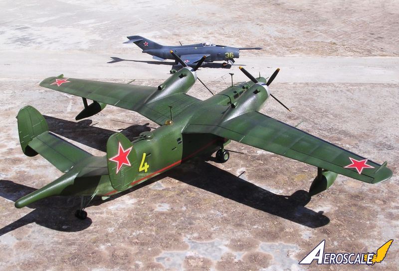
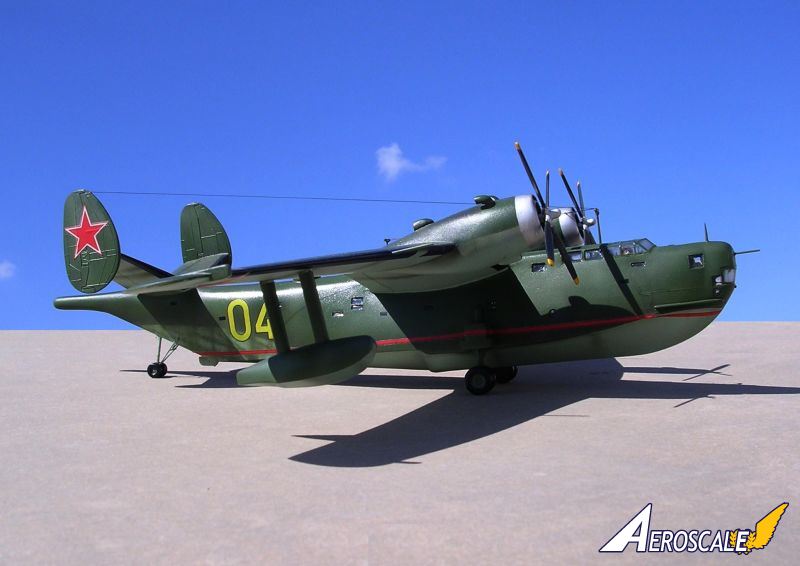
A good number of Be-6s were finished in olive green upper surfaces and light blue/grey undersurfaces. On my model I applied two shades of olive green, one lighter than the other to bring out the weathering effect. The kit is supplied with a reasonable quality decal sheet. These only needed the transparent film trimmed off at the periphery otherwise the large red stars makes the kit look complete. A large yellow number "04" which is neatly outlined in thin black was ideal for the exact version 1 have made. A long red water line decal trim was carefully applied to the hull. Other weathering effect was added by airbrushing engine grey to areas aft of the exhausts and engine-cowling front. Cowling rings were completed in silver paint. A soft edge merging separated the upper olive from the lower blue/grey finish.Alternative fuselage identification numbers carried by various types of Be-6 have been noted on photos. These include 1, 02, 07, 14, 11, 15, 10, 5, 47 and 24. Some early Be-6 and also others that went late into service were finished light grey overall. The Peoples Republic of China also had Be-6 in service on maritime patrol. A particular one was in overall grey finish, which carried large red identification number 89706 on the forward fuselage beneath the cockpit and the red star and bars in all the appropriate positions. Apparently the Chinese went further in developing the Be-6 as the one being referred to is powered by a pair of turboprops in place of the bulky radial engines. The turbo props closely resembled the Ivechenko AI-20 powerplants normally seen on the II-18.
Conclusion
The VEB Plastikart Be-6 Madge may indeed be a challenge to construct, modify and add detail to, but in the end it is very rewarding with a pleasing result, producing a Soviet aircraft that for many long years we knew little about, until not so long ago.Reference:
Observers World Aircraft Directory - William Green
L&K issue No.8. 1980
About the Author


Comments
Carmel, another outstanding build and modification of an unusual subject. Your corrections and additions to this ancient kit is remarkable.
Joel
FEB 02, 2014 - 03:02 AM


Hi Carmel
Wonderful job on the old kit! I've had one stashed away since about 1980 and I'll certainly refer to your corrections if I ever pluck up the courage to tackle it.
All the best
Rowan
FEB 09, 2014 - 09:26 PM
Copyright ©2021 by Carmel John Attard. Images also by copyright holder unless otherwise noted. The views and opinions expressed herein are solely the views and opinions of the authors and/or contributors to this Web site and do not necessarily represent the views and/or opinions of AeroScale, KitMaker Network, or Silver Star Enterrpises. Images also by copyright holder unless otherwise noted. Opinions expressed are those of the author(s) and not necessarily those of AeroScale. All rights reserved. Originally published on: 2014-02-01 03:16:28. Unique Reads: 5368

WEB HOSTING BY


Copyright ©2021 AeroScale and Kitmaker Network, a subsidiary of Silver Star Enterprises
All Rights Reserved. Please read our Conditions of Use and Privacy Policy.
All Rights Reserved. Please read our Conditions of Use and Privacy Policy.