

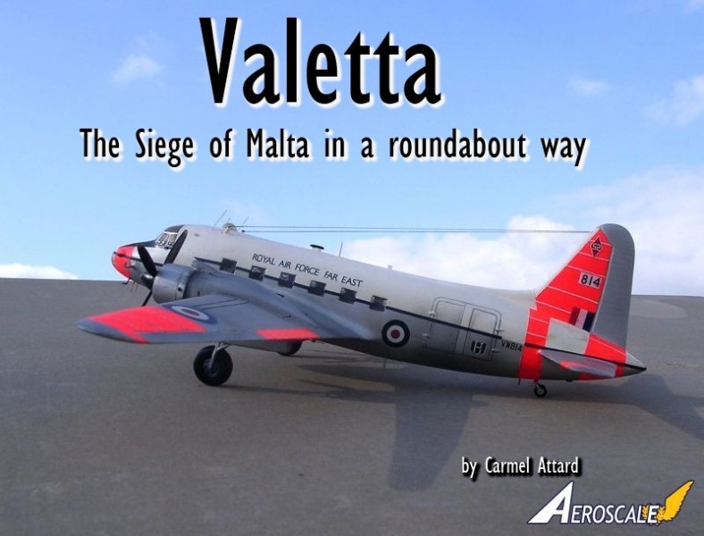
1⁄72Valetta
1
Comment
history
The aircraft name Valetta is a corrupted title derived from the name Valletta, the capital city of the Maltese islands. The origin of the name Valletta comes from Gean Parisott de La Vallette. In late spring of 1565, the Turks under Sulieman The Magnificent invaded the island of Malta, just off Sicily. La Vallette was the 72-year-old Grand Master of the Order at the time that fought in the battlements in the hot Mediterranean summer alongside his beloved knights of the Order of St John of Jerusalem, Knights Hospitalers.They were outnumbered, besieged, trapped by an enormous merciless, veteran Turkish Army. Sulieman knew, as did Adolf Hitler and Benito Mussolini; he could not control the Mediterranean Sea until he held Malta. In spite of the immeasurable might on the warrior-monks and the local inhabitant recruits, the Maltese and Knights emerged victorious after 5 months of continuous daily attacks, of never ending cannonade and prevented the Mediterranean from becoming their private lake of the Turkish armada. The Knights Hospitaliers and their men-at-arms and locals fought. Five hundred knights and 5,000 men-at-arms against 60,000 Turks including the admiral of the fleet Dragut .read the number over and over again. 30,000 Turks left dead the Turkish expansion into Europe came to an abrupt halt. This dramatic account is based on historical records.
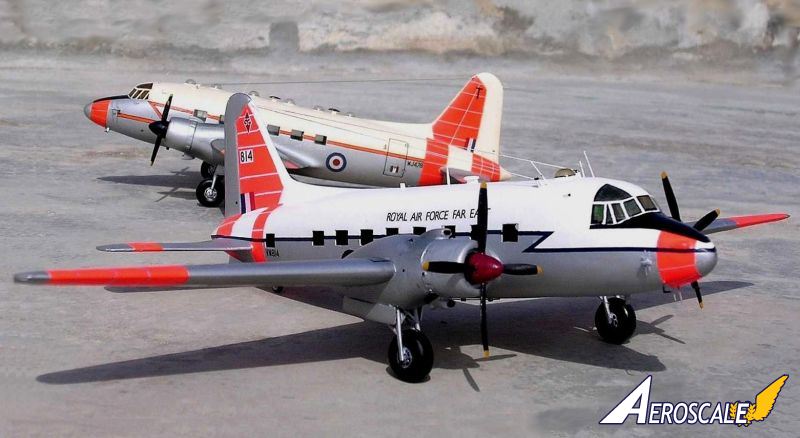
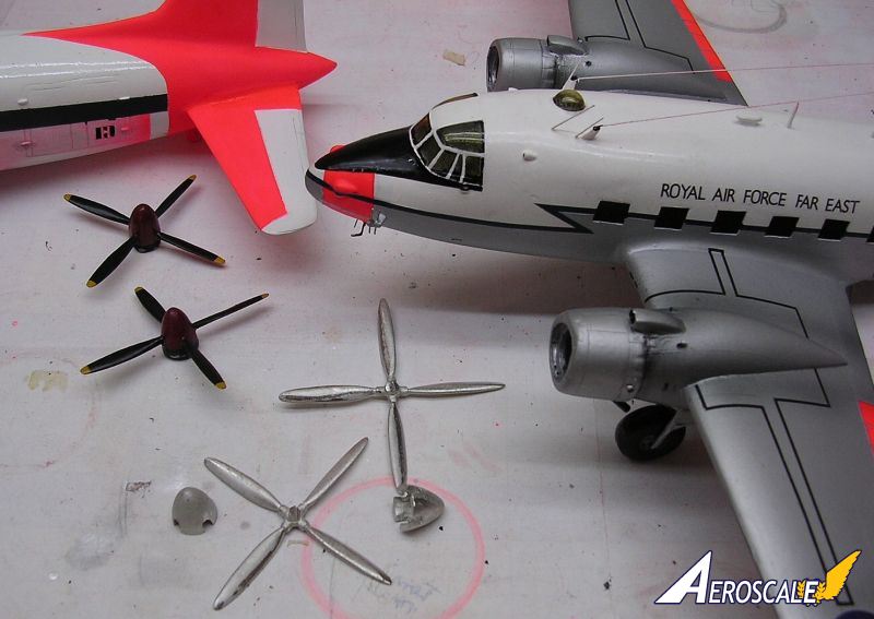
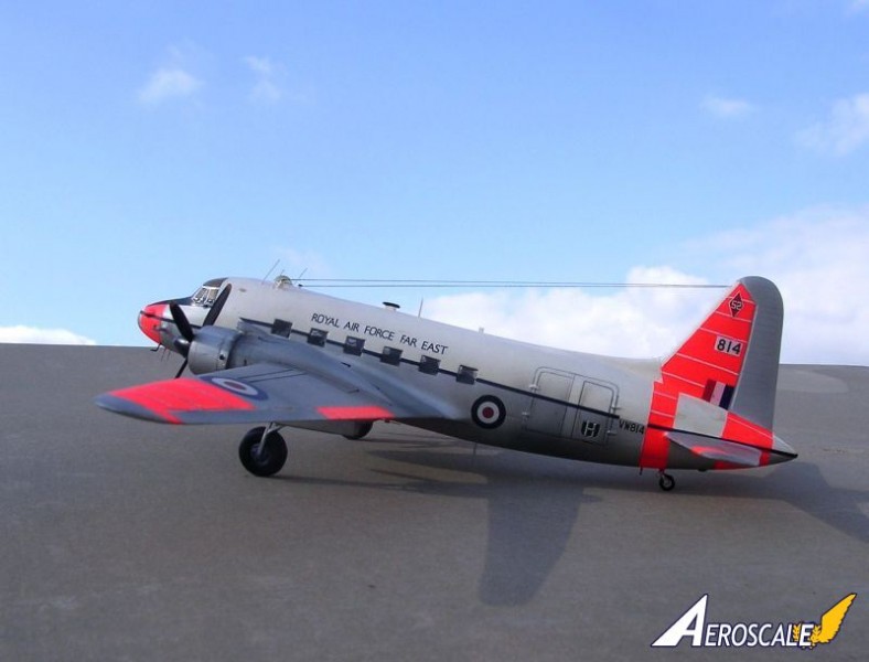
The Valetta aircraft was a military development of the Viking airliner as a medium-range Transport aircraft for the RAF. These aircraft shared several common features and resemblance to the wartime Wellington bomber from which both types evolved. As a transport the Valetta was fitted with strengthened floor and a large freight door at the rear of fuselage, port side. Valettas of the Far East Air Force transport wing operated over the Malayan jungle in support of British troops while others performed a variety of roles apart from logistic duties at different RAF bases in different parts of the world
the model
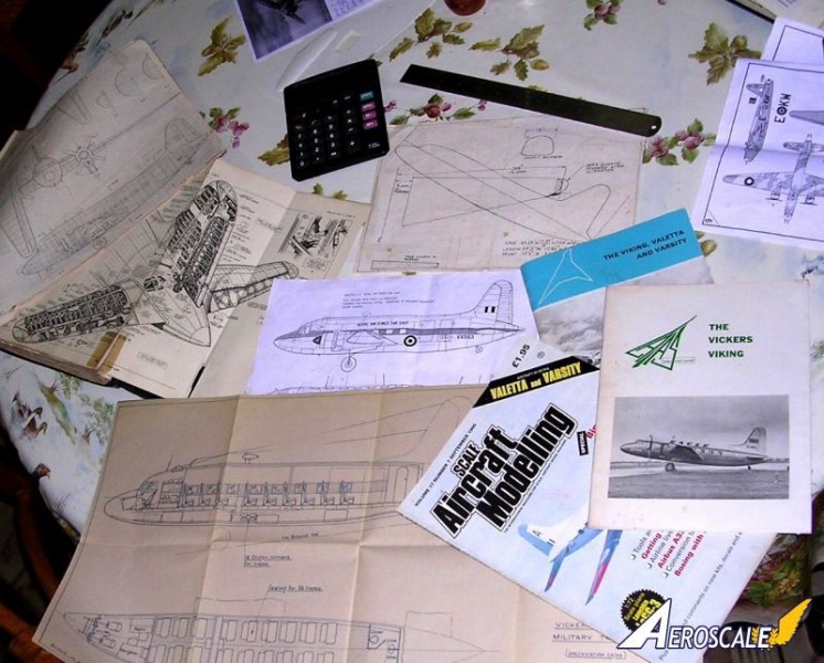
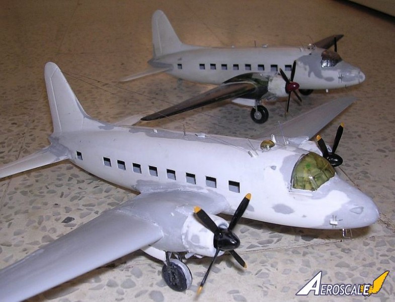
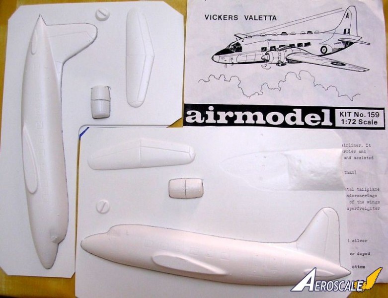
Modellers who have been in the hobby for some time are in no doubt familiar with vacform kits as those produced by Contrail, Rareplanes, Esoteric, and Aeroclub etc. Vacform kits that have been around for some time are those produced by Airmodel, and who also happened to produce a reasonably priced vacform conversion kit of the Valetta which is intended to go with parts of the Airfix Wellington kit at a scale of 1/72.The kit comes in as one white polystyrene sheet, which contains the fuselage halves of the Valetta, tail planes and engine cowlings along an acetate clear sheet containing a perspex cockpit. In making a start on the Valetta kit one need to decide from early stage the version is to be made i.e. C1, T3 or a T4 which all have little variations between one and another. The first one I built was a T3 which was some time ago and more recently I decided on two C1s in view of the connections this have had with the local station flight when Malta offered facilities to the RAF at both taQali and Hal-Luqa. Over the years I have accumulated a reasonable amount of reference material and photos so that I will be able to make scale models of the Valetta as accurate as I could.
Nowadays the Valetta/Viking is produced in injection moulded kit form but this did not alter my plans to utilise the vacform kits that I had in my stash and besides I do recommend this conversion even to the first time modeller who wants to start building vacform kits.
construction
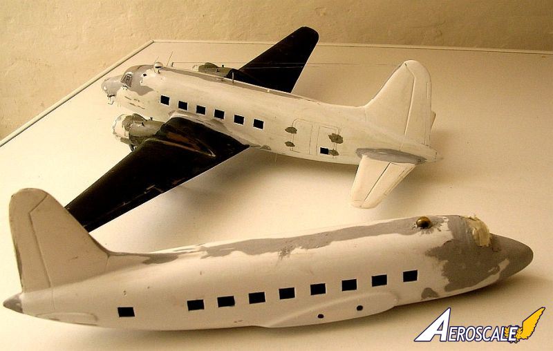
Several parts from the Airfix Wellington bomber kit are suitable to use to make the Valetta. Basically these are the wing halves and the undercarriage parts. Modellers are therefore advised that the work involved in this conversion is within the ability of the average modeller who already has acquired the basic skill of plastic modelling if a successful result is to be achieved. I used to find that rubbing and filing down vacform parts as time consuming when I started my first vac form kit. This is not so today and care is always needed with every stage but each modeller will in due course develop his or her own technique.Having cut the two fuselage halves from the polystyrene by scoring the outline with a sharp modelling knife, the first task is to rub down the joint lines to ensure that a good match and fit can be achieved when the two halves are stuck together. I found that the best way to do this is to have a large sheet of wet and dry sanding paper placed with a small fold under the edge of a 1/2thick x12x 6 wooden flat piece. Double sided tape will achieve a good fit of these together. The next step is placing each of the fuselage halves on this sanding paper and starts rubbing backwards and forwards to obtain a satisfactory finish fairly quickly. The front engine nacelle parts, which are also supplied, are also dealt with in this way. The next step is to carefully mark with a pencil the series of rectangular windows and each corner is drilled using a 1/8 twist drill. The four corner holes are then cut with a sharp modelling knife until a series of square windows are produced all being equal is size and shape. To complete this first stage the cockpit is also cut and the finishing of this is left to a later stage. The cutting of the astrodome opening is left to a later stage i.e. when the two halves are already joined together.
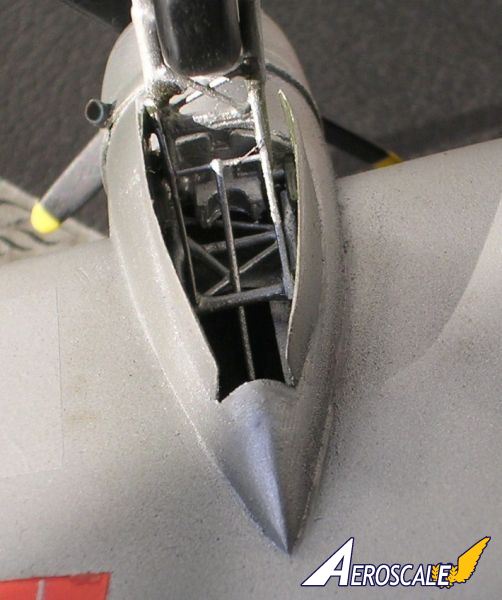
The interior to the cockpit as cabin floor, bulkhead, seating arrangement, instrument console and control columns and rudder pedals are also scratch built and added at this stage after reference to photos and drawings of this area. The layout is painted light grey with touches of black and dark brown seat cushioning. Interior of the VIP and /or freight area and floor are also painted at this stage. Intricate detail to this area is not recommended as the window panes are made of Kristal kleer which although is clear any detail added will be lost in the end. In the case of the T3 I have resorted to square cut clear Perspex windows.
The pilot and co-pilot seat were made from scrap polystyrene sheet coming as backing sheet with the vacform parts. Strips from same source, which are about 3/16 wide, were added around the edge of the fuselage at alternate distance to each half. These will act as self-alignment and reinforce the parts when these are glued together. I found Humbrol liquid cement very effective to do the job and produce a strong bond. After the fuselage was allowed to dry out thoroughally, putty was applied to joint lines and other areas around the nose to obtain the correct contour or to fill up depressions and other surface imperfections that are normally present on this vacform kit as it is starting to show its age. Needless to say that constant reference is made to a selection of photos and scale plans that I had at my disposal. Using various grades of wet and dry sanding and reapplying body putty wherever needed I was able to obtain a much desired smooth round surface and in doing so completed the work satisfactorily.
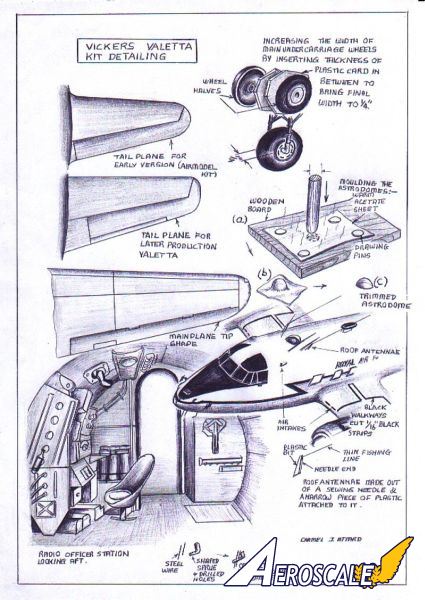
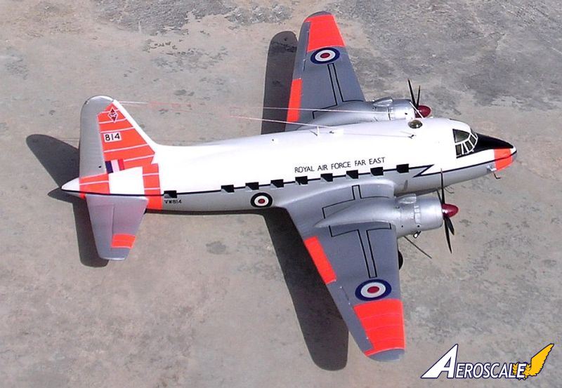
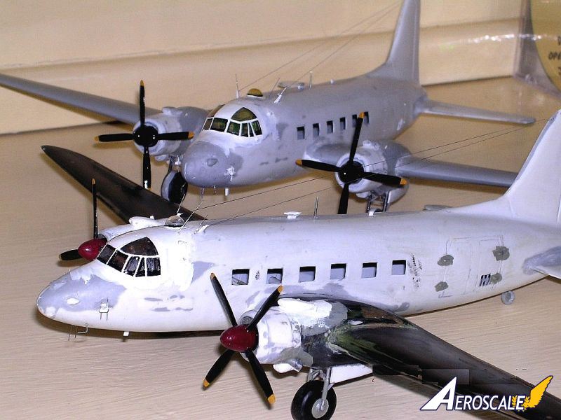
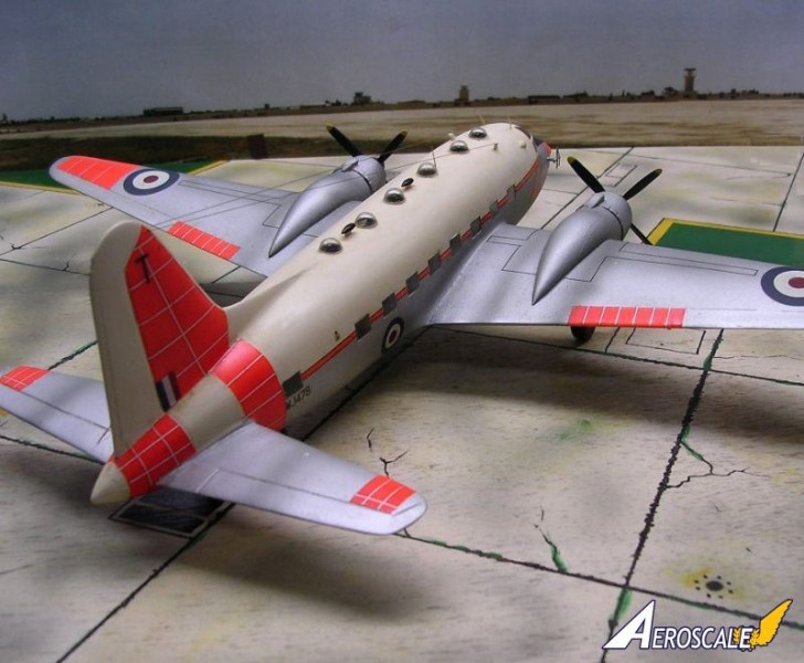
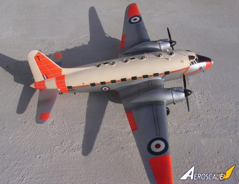
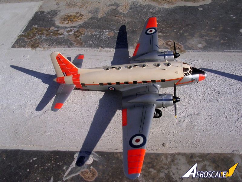
At this stage one will notice that the principal exterior difference between the T3 and the C1 version was that the T3 carried six astrodomes for use during navigation training while the C1 only had one astrodome used for observations. Therefore I simply had to accurately mark the position of these astrodome with respect to the version used and drilled 9/16 diameter holes. Frequent checks using a wooden stick of same diameter was used as go/no go gauge in order to produce equal diameter holes. The astrodomes were made from acetate clear plastic that I accumulate from new shirt collar stiffeners and chocolate wrappings using male/female method and a small burner of the kitchen cooker. The mould male was made from the same 9/16 d wooden male mentioned before with the end rounded with a smooth file to take a hemisphere shape. Eight astrodomes were needed to make the three models but I did make a few extra ones to replace lost or damaged ones.
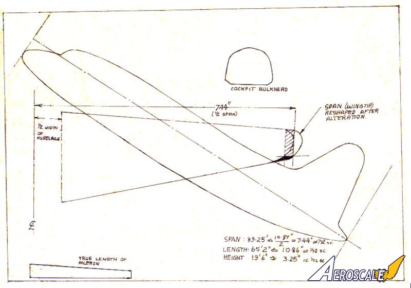
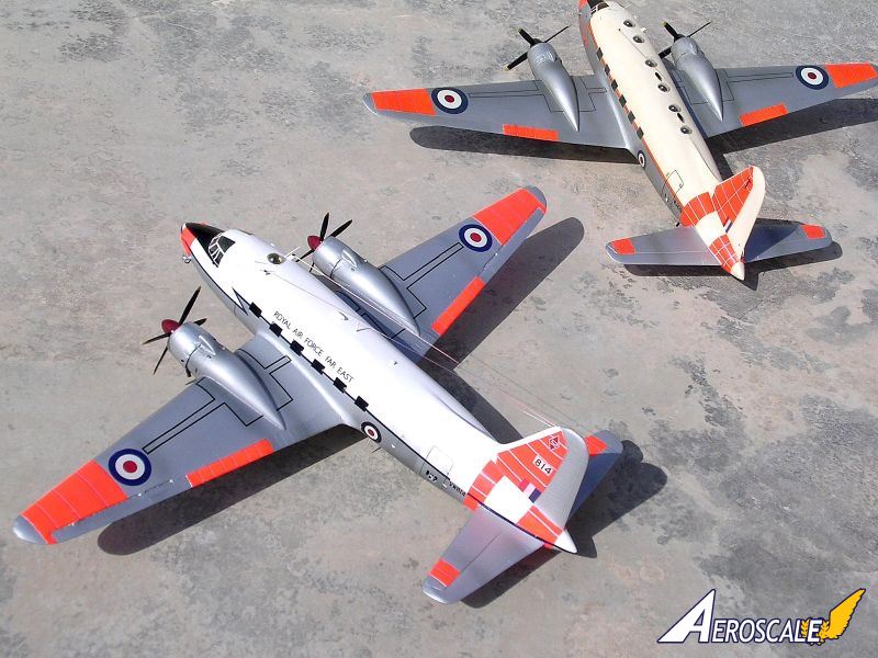
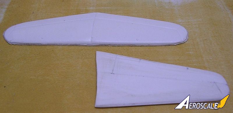
Using the Airfix Wellington parts 40, 41,37,38,36 and 39, one needed to do some alteration first. Each wing was assembled and a line was marked chord wise and ¼ from the wing tip from where the wing was parted using an exacto saw. The wing span was then measured so that the final overall span measures exactly14.87 or better still 7.44from the centre-line of the fuselage. To simplify the accurate measurement of the span, a slot is cut at the wing root of the fuselage to take the locating flat pegs on the inner wing area. This will indicate that the new wing tips have to be about 1/4 inner in the wind and so this amount is cut from the sawn off wing tip before the tip is rejoined to produce a new wing. The trailing edge of the wing tip area is then faired gently using a smooth file to produce a corresponding smooth outline. The surface geodetic structure detail associated with the Wellington wing is also removed using a generous amount of wet and dry until this will disappear. New panel lines and elevator areas are then scribed using a sharp scriber, thin steel ruler and steady grip. The next stage is to produce a new set of tail planes. I have found that those produced by Airmodel conform to very early Viking design and match exactly with scale plans that I have coming from the March/April 1947, Aeromodeller magazine. The other Valetta tail planes were much bigger in overall size using Aviation News plans. Nevertheless these same parts were cut, sanded to correct section, joined together and were extended at the root end to bring to correct area after these got dry and sanded to shape. The tail planes were then drilled at the edge so that locating pins are added to assist to secure in place when joined to the rear fuselage. Be prepared however to carefully align the parts to correspond well with the tail section and these should be level when viewed from the front or rear. Putty is added to the root to produce the required small fillet by sanding to correct appearance. This in the end becomes a straightforward job in view that I had to repeat it three times in my case.
Bearing in mind that the Airfix Wellington is some 50 years or so old kit I also noticed that the trailing edges needed trimming down the section to bring to a fine thinner edge. Fixing the main planes was simplified by first cutting a simple cardboard template in the shape of the lower surface of the wings looking from the front. This was made secure in a way so that it will stand on its own and the assembled model would rest on it while the glue is setting and at the same time giving the main planes the correct anhedral while drying for the next 24 hours. The joint area at the root was then given a coat of Plasto body putty to produce a smooth fillet. Airmodel suggests that that the engine cowlings and propellers come from an Airfix Bristol Super Freighter. As I already have plans for two Freighters in RCAF and RNZAF scheme I decided not to spoil any of these and instead I have used the Airmodel kit cowlings, and the props and Spinners were on one of them obtained from the Aeroclub range of white metal props. These were very accurate in shape and outline and on the others I used scratch built ones using Contrail struts to produce the blades etc.
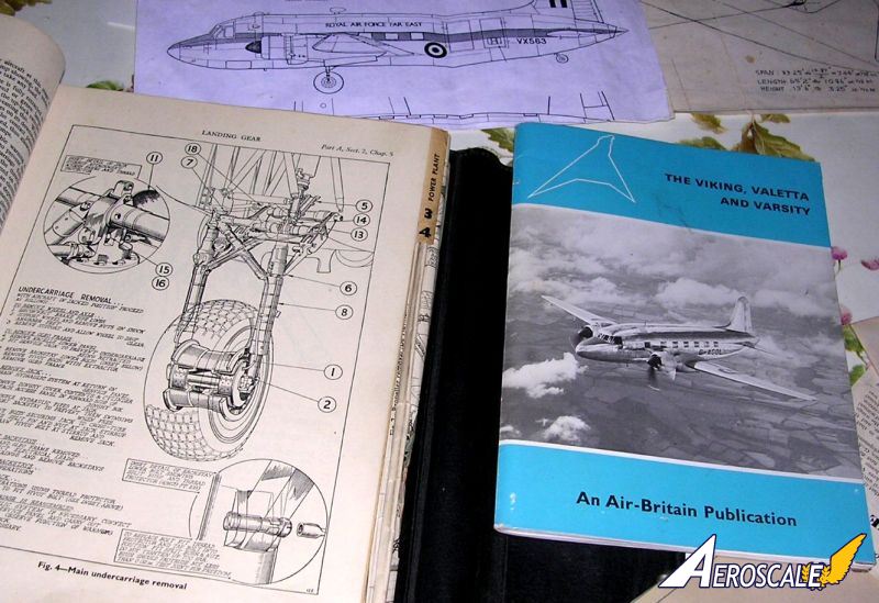
For making the undercarriage, the following Airfix parts were used: 56, 57, 58, 59, 54, and 55. The difference being that the wheels needed to be thicker using plastic card spacers to bring this to correct dimension. Wheel well doors were also made from plastic card, which were bent to correct shape and cut to size. Part 72 was utilised as a tail wheel and detail added using stretched sprue parts.
Fixing the clear acetate cockpit part was left to the final stage. This was first cut close to the size required using a pair of scissors and taking care not to initiate cracking to the rather thick clear Perspex. The next step was to trim the contact edges using a sharp trimming blade. A measured amount of putty was all that was needed to have a sturdy fit with a small amount of super glue added to the exterior joint surface away from the clear areas. Wing tip lights were cut at this very final stage. Small Perspex pieces were stuck in the space using super glue and when dry these were shaped with a smooth file followed by fine wet and dry.
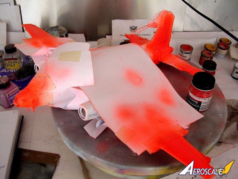
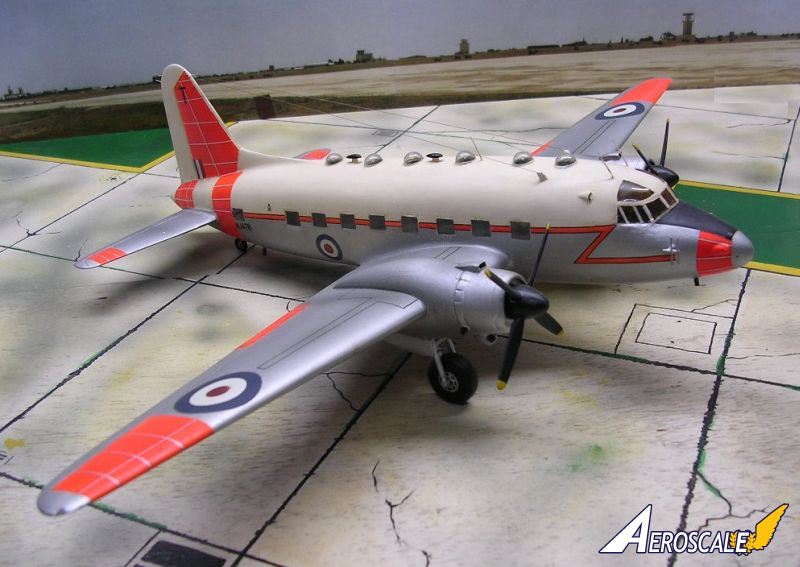
The final stage consisted of detailing the models. This comprised of reshaping the air intakes on the cabin roof and around the engine nacelles. The kit was then given a semi matt white overall finish and any imperfections that still remained which stood out were treated accordingly. Cockpit framing was carefully hand painted using a thin brush, around thin masking tape wherever this was required. Tiny antennae around cockpit, door hinges, small fairings, wireless, and other detail to the undercarriage were also added.
colour and markings
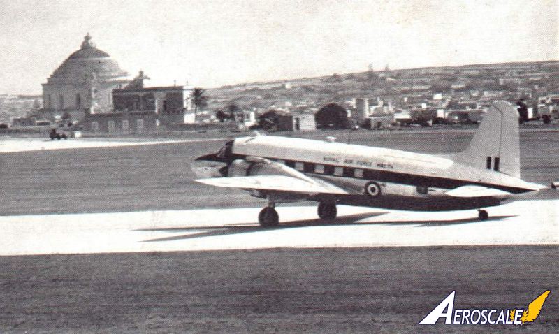
Each kit was given its respective colour scheme using Humbrol, Revell, and Modelmaster colours. I found that the local Hampel brand silver ideal for the metal finish. This was mixed with a tint of white and few drops of Revell clear satin varnish for best results. These were mixed well and thinned down to accommodate the airbrush extra fine nozzle.The list of those Valettas that at any one time served with the Malta Communications Squadron is quite numerous. Other Valetta came as regular visitors during transit.
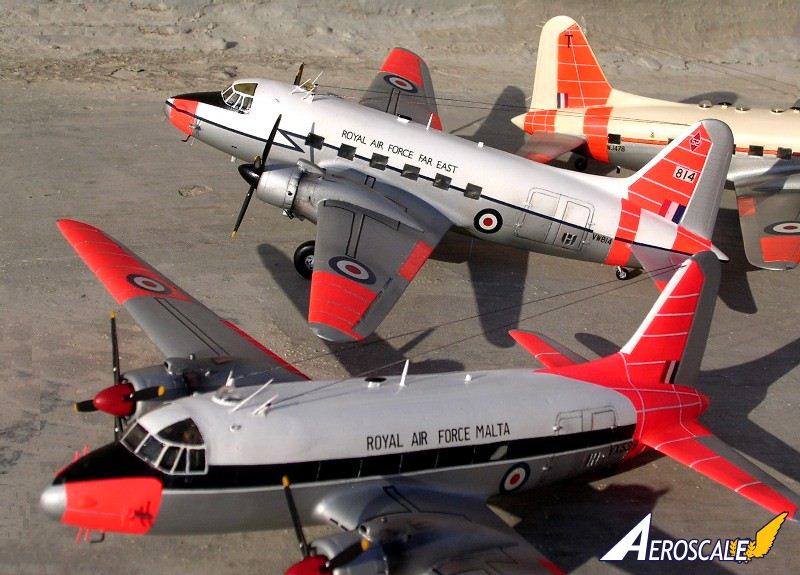
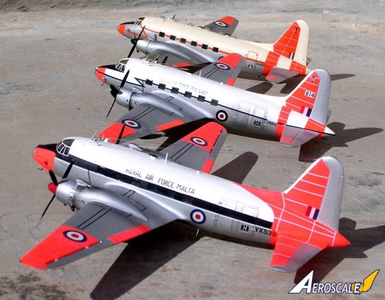
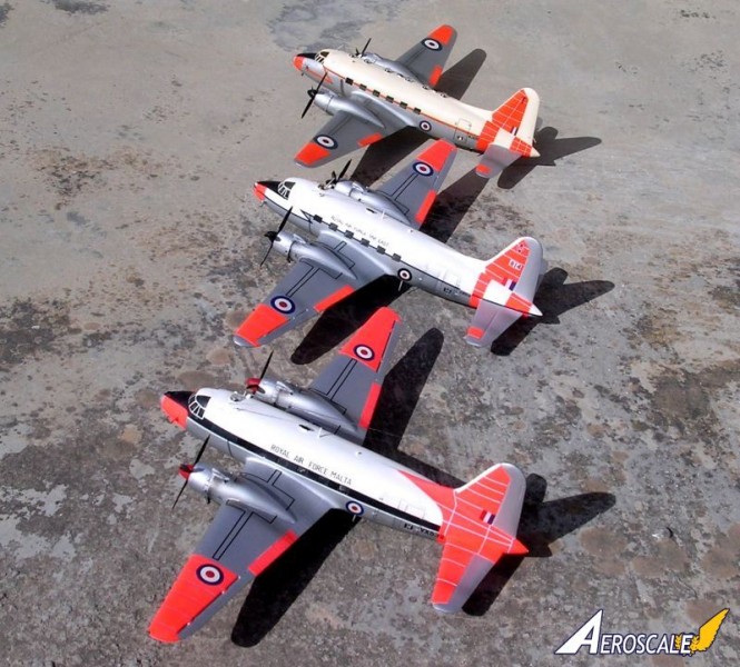
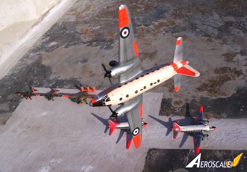
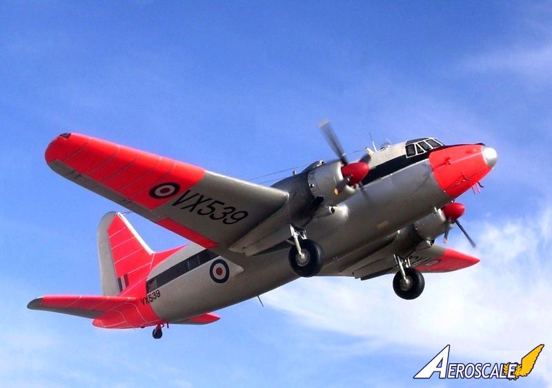
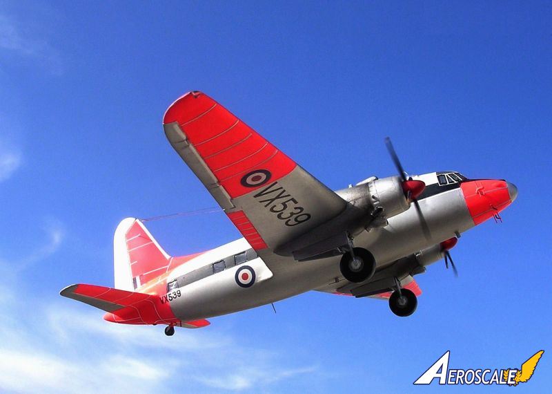
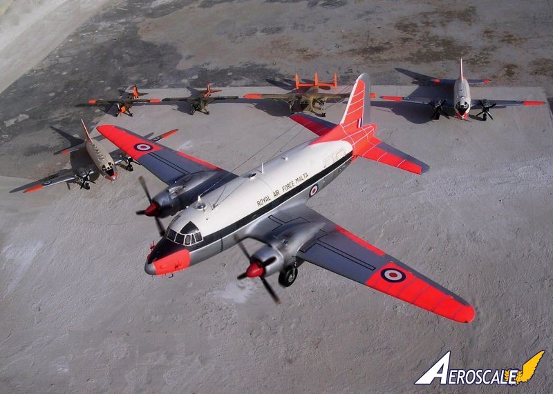
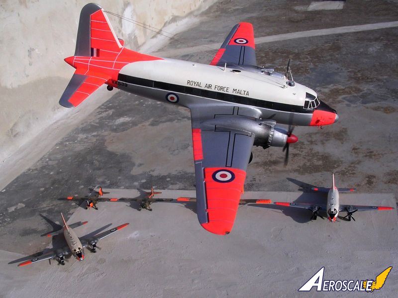
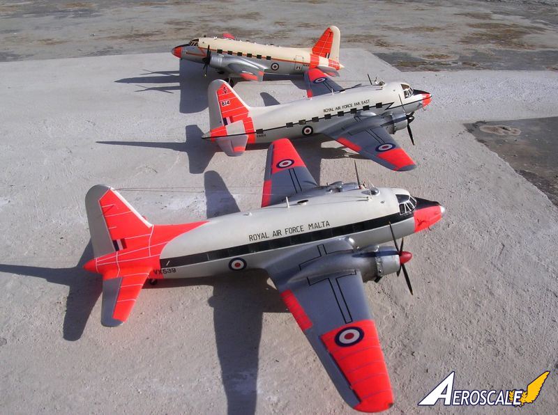
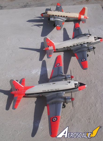
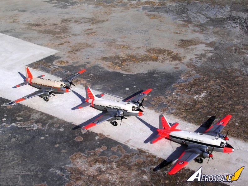
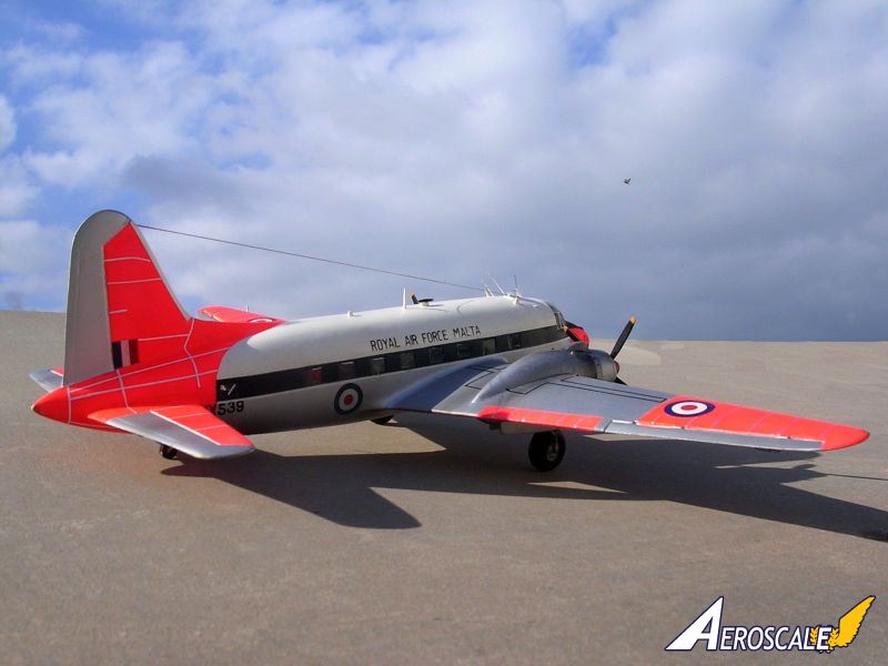
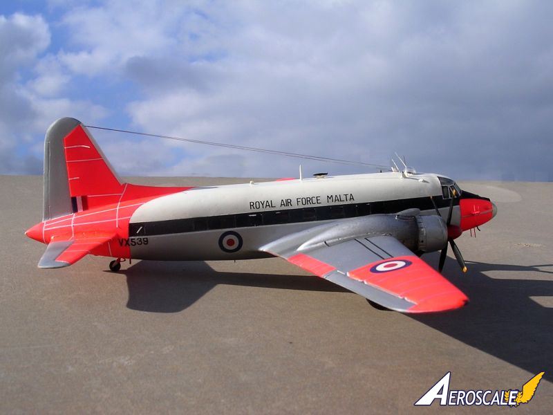
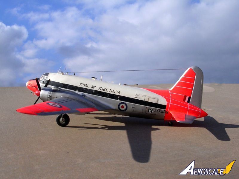
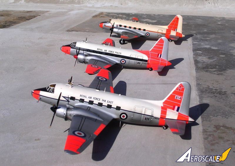
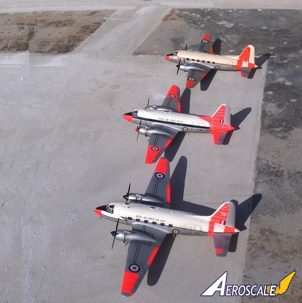
The three scale models of the immortal aircraft that I built all had some connection with Malta Either attached with the local station flight or came to Luqa airfield at some time as a welcome Visitor.
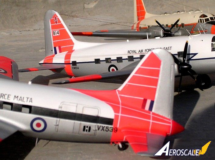
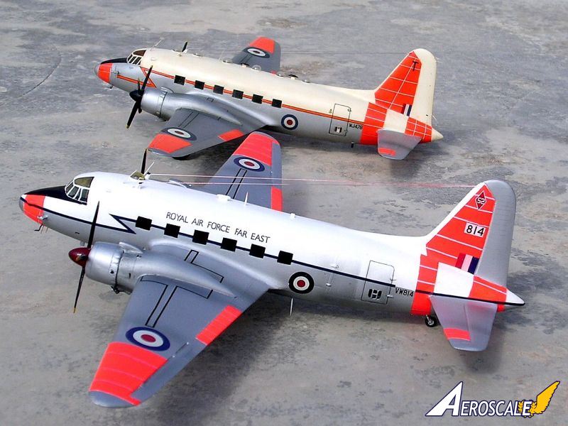
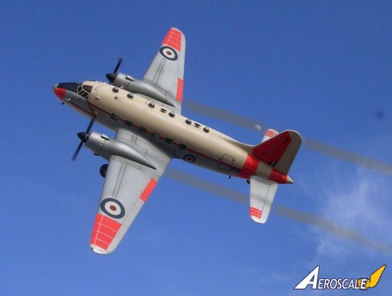
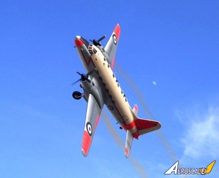
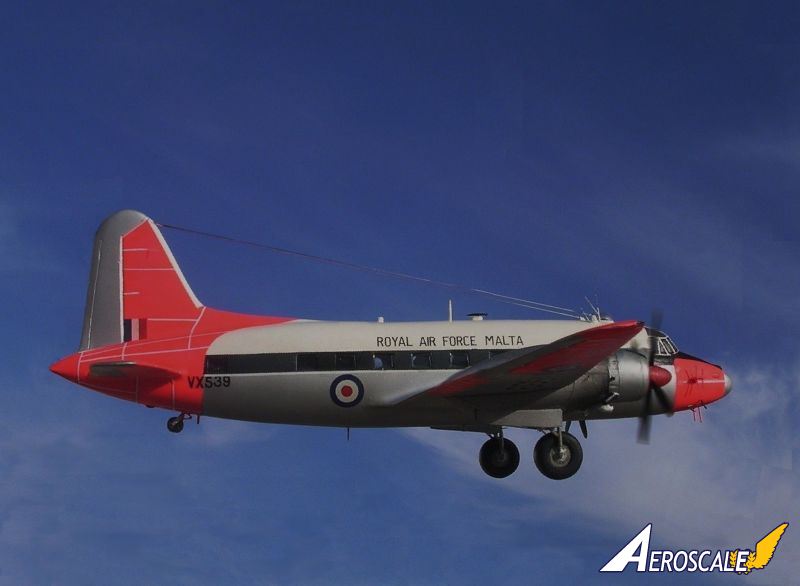
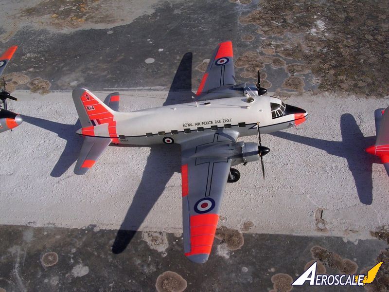
The decals I used came from various sources most of which came from the model Decals Range particularly the wing lettering and roundels. The No 52 Sq motif on the fin of one of themodels was hand made decal. Strips of black decal were cut to form walkways and fuselage trim, others made out of thin blue decal and then filling in between with brush paint. RAF MALTA was madefrom a Roodecal wording, Royal Australian Air Force, and adopting the lettering accordingly.
The parting line between the Day-Glo panelling was produced by thin white and silver decal strips depending on the area where the Day-glo orange was. A fair amount of exhaust weathering was applied to all effluent areas and finally the wheel and anti glare areas were given a coat of matte varnish.
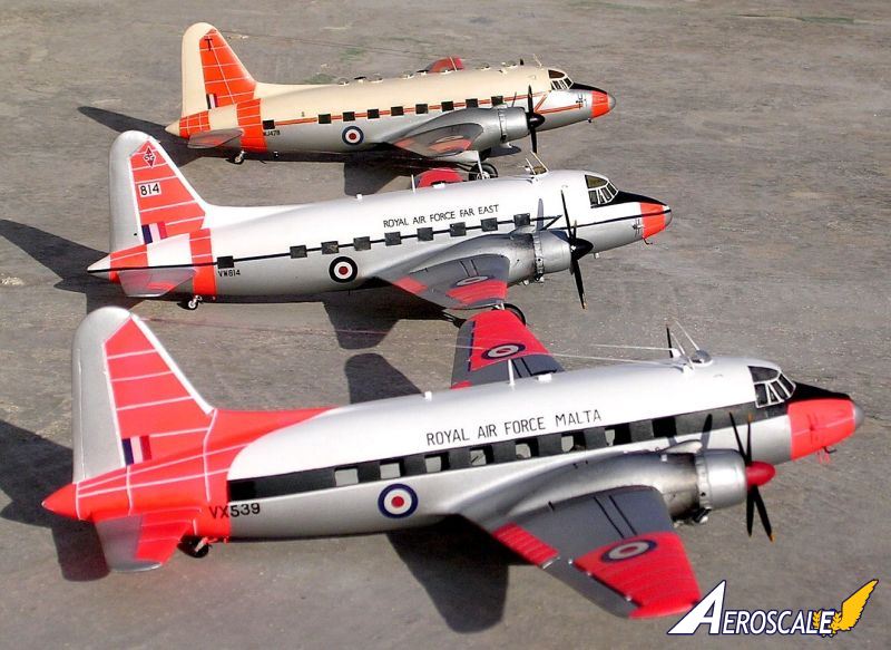
The three scale models represent as follows:
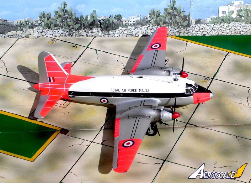
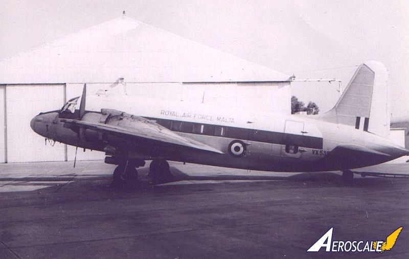
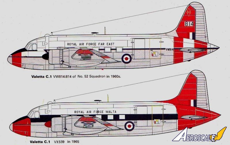
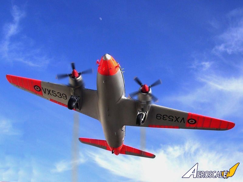
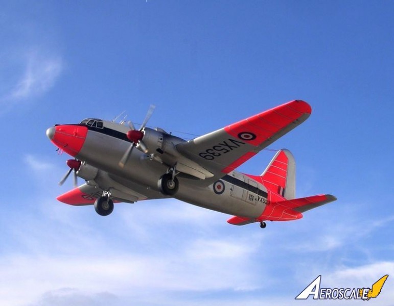
- 1. Valetta C1: VX539. No of production line at Weybridge 181 Construction number: 468 Type 561/1, first flew on 24-5-50 Served with the Malta C&TT Sqn 4-62 till 9-65 SOC: 28-2-66 used for fire fighting practice at Catterick.
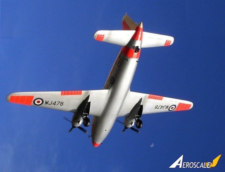
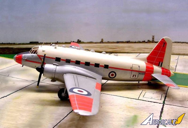
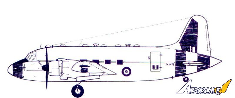
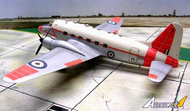
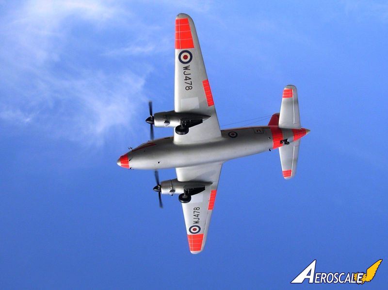
- 2. Valetta T3: WJ478, Construction number 603 completed as type 664 Valetta T3 Visited Hal Far, Malta in 1966
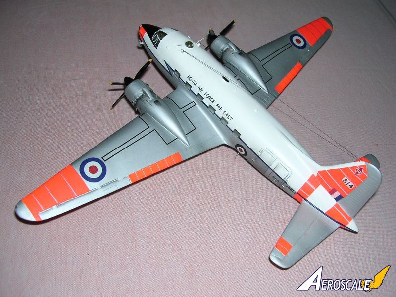
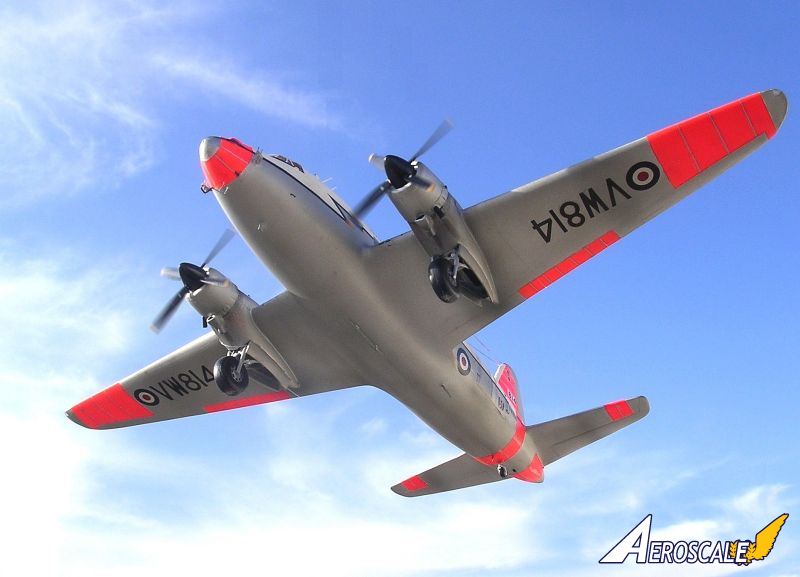
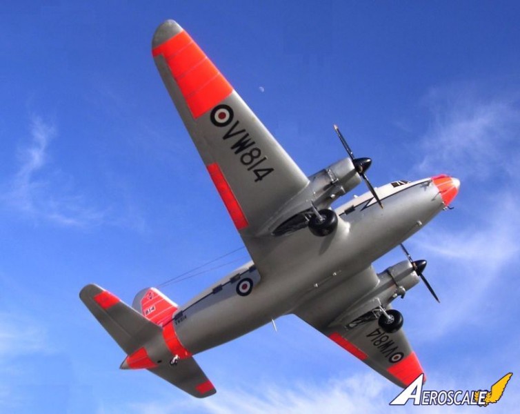
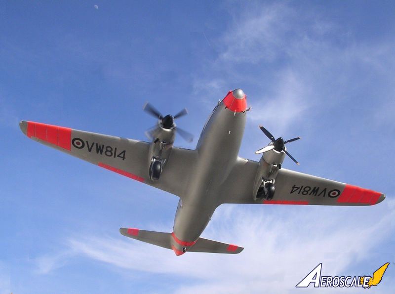
- 3. Valetta VW814, Construction number 375 as Type 561/1. Served with Far East Comm. Sq 12-60 to 10-61 with 52 Sq codes 814. 10-61 to 6-62 and 12-64 to 4-66. Struck off charge 6-5-66. Visited Malta 16-12-64 while with 52 Sq ferry to Butterworth, Malaysia.
conclusion
The end result was quite pleasing and hopefully in not too distant future I should make an exception and add a civil aircraft type. An Autair or British Airways Viking using the same kit conversion and build procedure.REFERENCES
- 1. Aeromodeller March/April 1947 scale plans
- 2. Workshop Manual Vickers Viking Autair International No42 July 1948 Publication
- 3. Quarter scale drawings Valetta Mk1 Specification c9/46 Drg 45382 sheet 2 issue B EDH Aug 1946 PS Jan 47
- 4. The Vickers Viking a LAAS Int Publication Sept 1970
- 5. The Viking, Valetta and Varsity compiled by Bernard Martin issue ISBN 085130 0383 3 an Air Britain Publication
- 6. Aviation News scale plans
- 7. Aviation News Vol17 No7 Aircraft in Detail
- 8. Information forwarded by R.Robinson of Fife, Scotland, about Malta based Valettas.


Copyright ©2021 by Carmel John Attard. Images also by copyright holder unless otherwise noted. The views and opinions expressed herein are solely the views and opinions of the authors and/or contributors to this Web site and do not necessarily represent the views and/or opinions of AeroScale, KitMaker Network, or Silver Star Enterrpises. Images also by copyright holder unless otherwise noted. Opinions expressed are those of the author(s) and not necessarily those of AeroScale. All rights reserved. Originally published on: 2014-01-04 03:56:20. Unique Reads: 4528

WEB HOSTING BY


Copyright ©2021 AeroScale and Kitmaker Network, a subsidiary of Silver Star Enterprises
All Rights Reserved. Please read our Conditions of Use and Privacy Policy.
All Rights Reserved. Please read our Conditions of Use and Privacy Policy.