

1⁄32Silver Wings CR.42 Build Guide
...
Post a Comment
general
This kit gives the builder the option to do either an Italian, German or Swedish version. Be sure to review the instructions and highlight which parts you will need for the version you are building. Also note that I used standard superglue for all assembling, with the exception of the struts, where I used slower setting superglue gel to give me more time for adjustments.parts cleanup
As with other Silver Wings kits, parts cleanup is fairly simple, and due to the soft resin they use for their kit, a sprue cutter can even be used to snip most parts from their pour stubs. After that, a few scrapes with the Xacto knife and/or sanding stick and the part is ready for use. With these kits, since there are no part numbers to worry about, I like to clean up all the parts and then begin the build. The only exception to this is the struts. Any parts can be painted as appropriate after cleanup and before assembly as well. A few things to note when preparing your kit parts for use:- Do not remove the number "tabs" from the struts (unless you mark them in some other way, such as a tape tag) as the numbers are crucial in aiding proper strut placement (Photo 1)
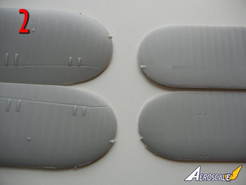
- The wings have excess resin rods on the upper tips (see Photo 2), these must be removed as the outer wing should be smooth.
- Check your fuselage framing for any breaks before you remove the pour blocks. You should repair any breaks with superglue before removing the pour blocks.
- If you intend to use the kit provided cockpit frame cross brace tubes, be sure to measure them before you remove them from the pour stubs as I found I had to trim carefully in order to not end up with tubes that were too short.
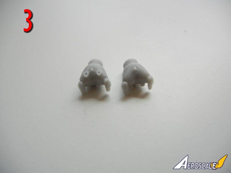
- Take care in removing the pour block from the seat back, as there should be a lip at the top. There are two different types of engine cylinders. Be sure to keep them organized as one set goes on the front of the engine, the other on the rear (front on the left, rear on the right in Photo 3).
- Some of the engine cylinders may have some slight seams on the sides that require cleanup, however any that you "miss" during cleanup will likely not be visible on the finished model without searching really hard for them.
- Test fit your propeller to the engine block and enlarge the hole as necessary to achieve a good fit.
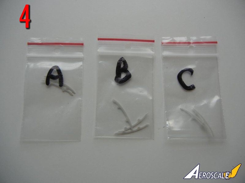
- The cockpit sides have 3 frames that must be attached, and are placed in bags labeled "A"; "B" and "C" (Photo 4). As they look similar, I recommend you clean up each set, and then place them back in the bags until you are ready to attach them.
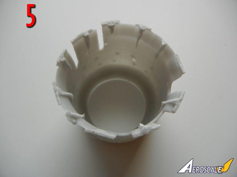
- The engine cowl has some pour channel remains on the inside of the cowl flaps (Photo 5). While a portion of these look like they may be actuating rods of some kind, they should be removed and the cowl flap area should be smooth on the inside.
interior subassemblies
There are a few items that can be assembled before installation in the cockpit, as indicated on page 3/4 of the instructions. I'll review them here:- Instrument Panel: Note that part PE-2 is for the German/Swedish versions, while part PE-2a is for the Italian version. Cut out the instrument backing from the clear film and paint the back white, and install in in position on the PE instrument panel. Prior to attaching the PE panels to the resin instrument panels, you should test fit the resin panels to the PE gun sight "box" as some trimming of the rear of the resin panels may be necessary to get a good fit (don't worry about destroying any detail, the back in not visible on the finished model). If possible, I recommend attaching the PE panels to the resin panels after the resin panels have been attached to the cockpit framing and test fit to the fuselage.
- I left parts PE-4 off of my build as they are not really visible on the finished model.
- Use the end of your paintbrush to bend the PE rudder straps into shape and attach them to the rudder bar. The provided PE shoulder belts and pad are "interesting" to assemble, but you can leave them off until the fuselage is completed if you prefer.
- While the PE control levers fit into the slots in the side control panel, you may want to drill small holes to give them a stronger attachment point.
cockpit assembly
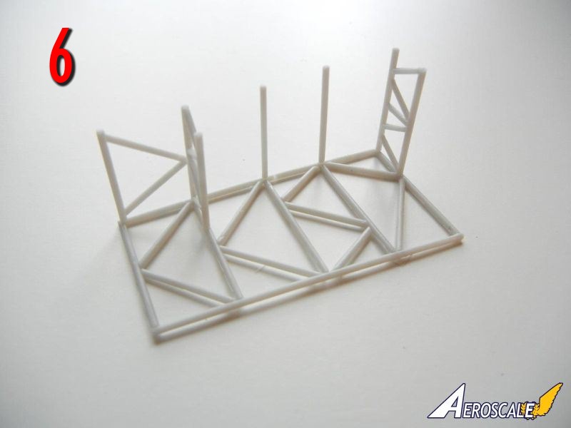
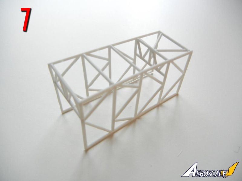
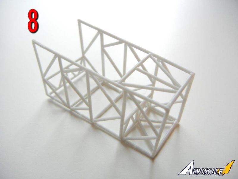
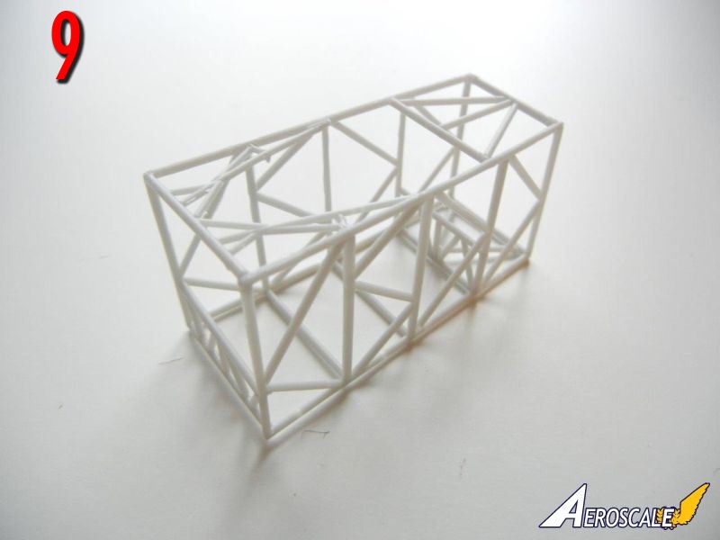
Cockpit assembly is shown on pages 2 and 5 of the instructions. If you've built any other Silver Wings kits, assembly should be familiar to you.- I started my assembly by cutting the provided resin cross-braces to the appropriate lengths as indicated (you may find it easier to use plastic or metal rod) on page 2. I then attached the rods and lower support frames to one side of the framing (see Photo 6). I then attached the opposite side framing piece, starting at one end and moving towards the other to ensure the best alignment (see Photo 7). I then added the upper rear framing (Photo 8) and finally the upper front framing (Photo 9). Once complete, test fit the frame into the fuselage to be sure everything is lined up properly.
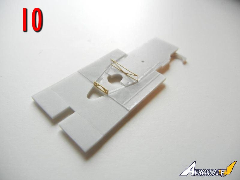
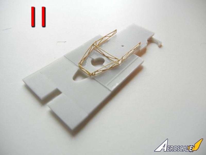
- Next, I attached the PE framing to the floor. I attached PE20 and PE21 and let dry (Photo 10). It would appear that PE22 is meant to be folded in half and then attached, but it was rather thick when I tried that, so I ended up cutting it in half and attaching it to the cockpit floor (Photo 11).
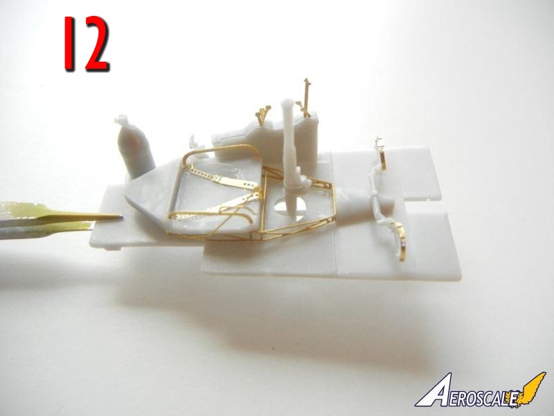
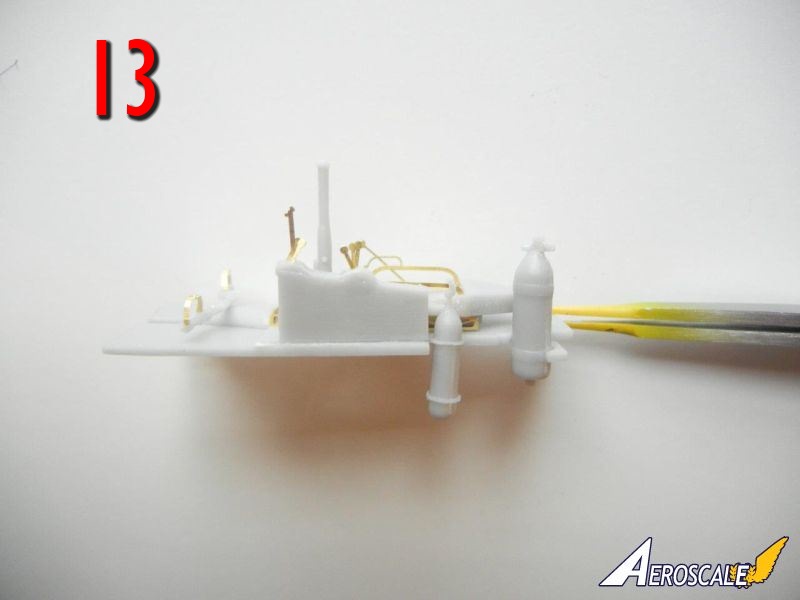
- Attach the seat subassembly in position, and then add the rudder bar, control column, and side control panel subassemblies as well as the two tanks (Photos 12/13)
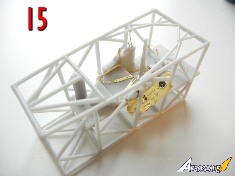
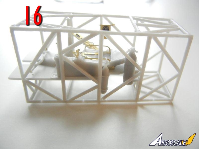
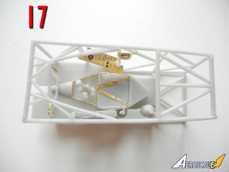
- Slide the floor into place, and then attach the PE side consoles as appropriate (see page 2 of the instructions) see Photos 14-17.
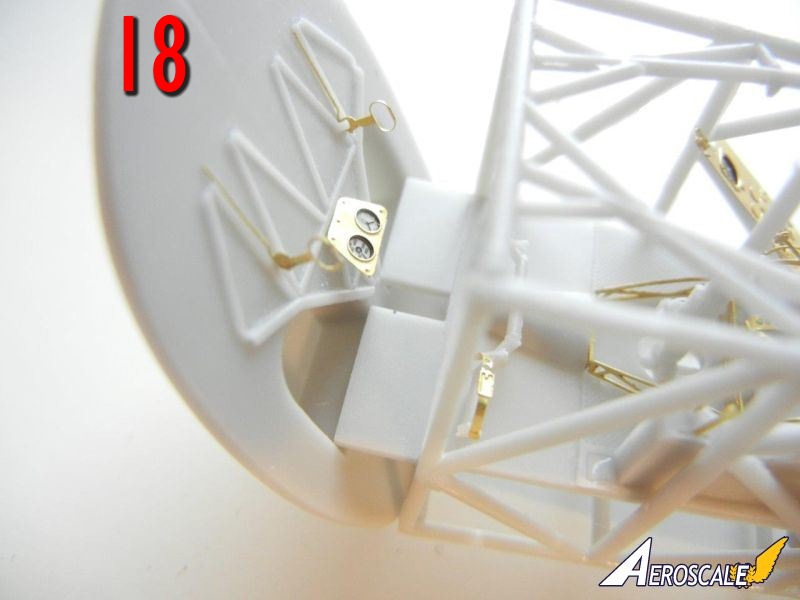
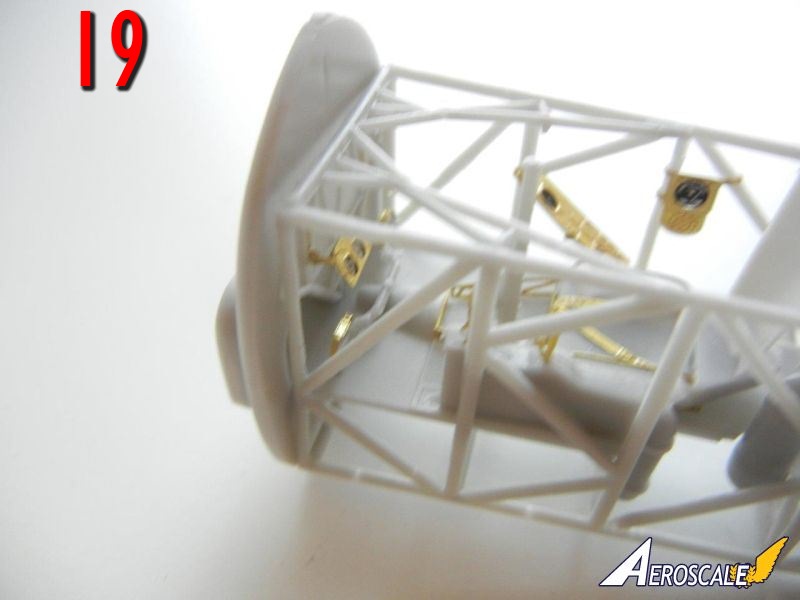
- I then attached the firewall subassembly to the front of the cockpit floor (Photos 18/19) rather than to the fuselage sidewall as shown on page 7 of the instructions. Fit was so good on mine I did not need to glue it, which gives the option to wiggle it should you need to for final positioning in the fuselage.
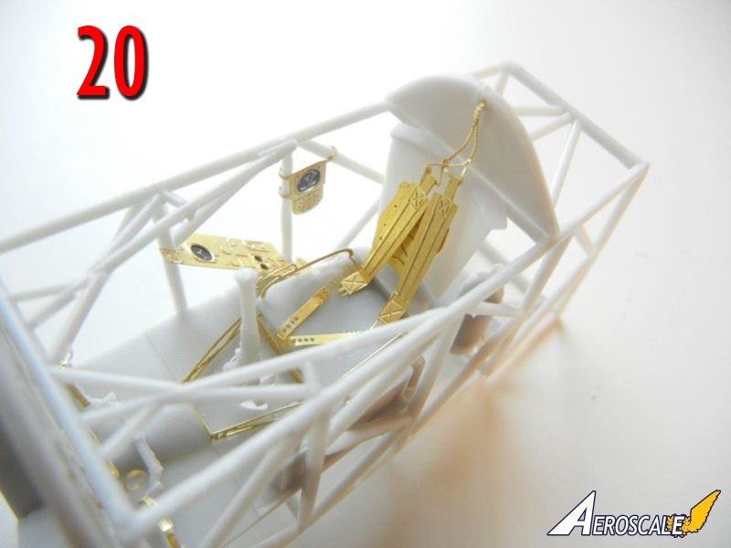
- Attach the seatback to the upper cockpit frame using the flange on the seat. You should be able to move the bottom slightly to get it into position. Attach the rear cockpit bulkhead in position on top of the seat flange (Photo 20). You can attach the shoulder belts at this time, or later in the build.
- Although not shown in the instructions, attach the instrument panel(s) 11mm back from the cockpit frame front. Test fit your completed cockpit in the fuselage.
fuselage assembly
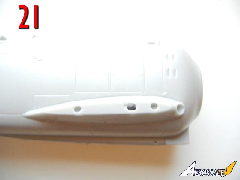
Fuselage assembly is covered on page 7/8 of the instructions.- Prior to assembling the fuselage, I drilled out an additional hole on each side of the wing root to allow the metal rod on the lower wing to fit into the fuselage (Photo 21)
- Test fit the windscreen to the fuselage, and trim the fuselage attachment area as needed to ensure optimal fit (namely the pointed area where the rear of the windscreen fits)
- If needed, cut and remove the section of the tail wheel fairing as indicated for the Swedish version.
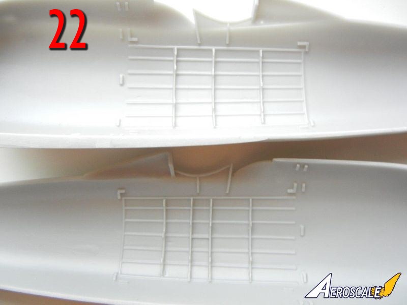
- Attach the fuselage frames (labeled "A", "B" and "C") into position as indicated (Photo 22)
- As mentioned previously, I prefer to install the forward bulkhead to the cockpit floor rather than the fuselage halve as shown in the instructions
- Attach the tail wheel (or trap between the fuselage halves if you want it to move)
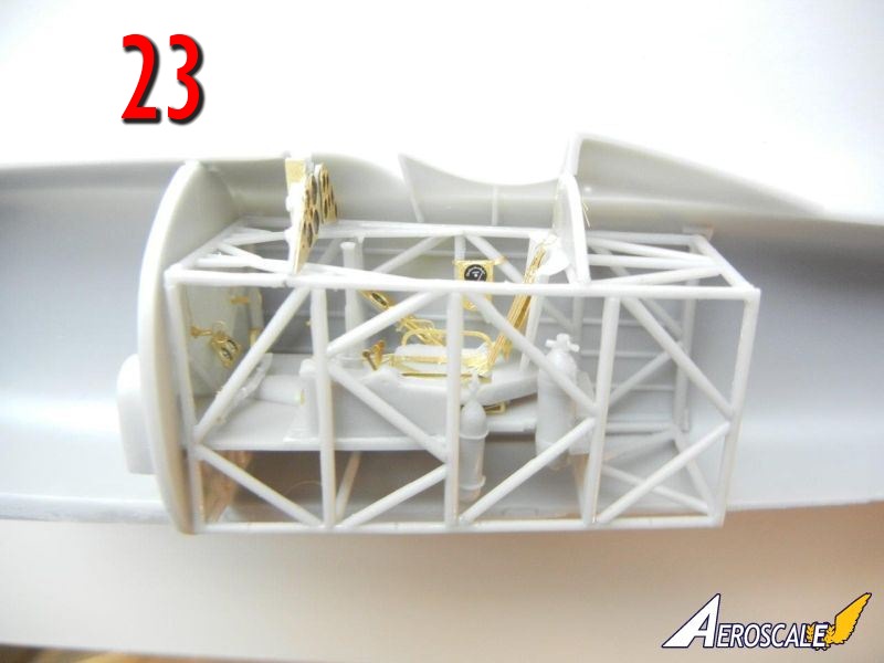
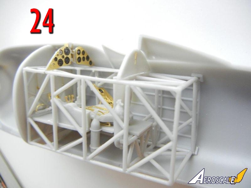
- Install the completed cockpit frame to one of the fuselage halves. Photos 23 and 24 show everything ready to be closed up.
- Glue the fuselage halves together.
- Attach the tail ski if you are building the Swedish version.
engine assembly
Engine assembly is covered in the upper section of page 6 of the instructions, although you can complete this step at any time during the assembly of your model.- Prior to beginning assembly, I recommend you drill out the pushrod attachment points on the front and rear crankcase, as it will make placing the pushrods much easier.
- Assemble the engine crankcases and manifold together as shown in the instructions. Do not remove the remaining rod that sticks out as it will be used to attach the engine/cowl assembly to the fuselage.
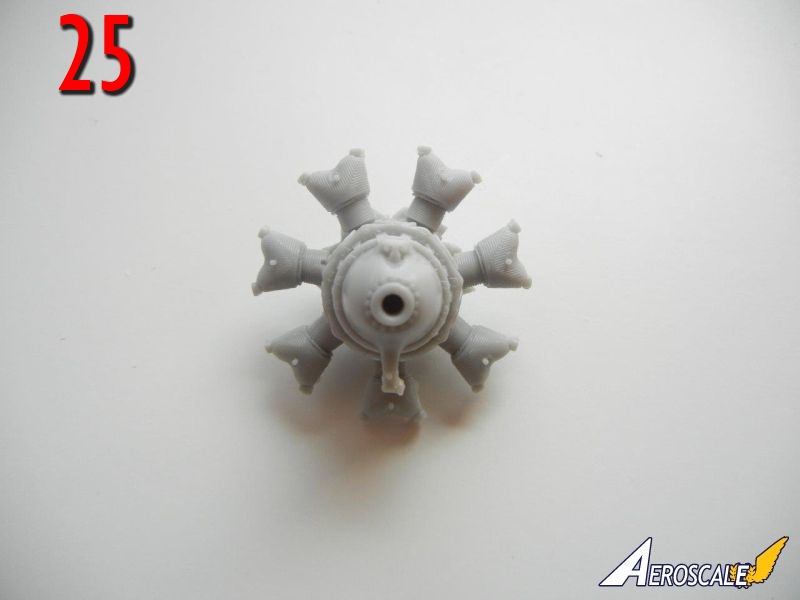
- I began assembly by attaching the back row of cylinders, being sure that each was facing exactly forward. See Photo 3 for assistance in determining which are the rear cylinders (on the right in Photo 3) if needed. Photo 25 shows the completed rear cylinder row.
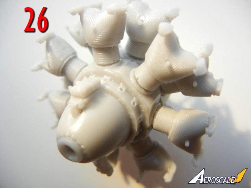
- When set, I attached the front cylinders. Photo 26 shows them in position (as well as the drilled out pushrod holes in the crankcase). Cut the pushrods (one or two at a time if you are prone to losing things like me) from their pour blocks and test fit it to the engine block/cylinder head by first inserting it into the drilled hole, and then pulling it up to meet the rocker on top of the cylinder. If the length is good, you can glue into place. Repeat the process until all 28 pushrods are in place, I would recommend the use of unpainted steel wire or rod rather than the kit parts for a more striking look.
- Once set, attached the intake pipes which fit to the left side of the cylinder heads (when viewed from the front) and to the manifold base. Add the parts that goes on the bottom of the front of the engine block.
- If you wish, you can add spark plug wires to the engine.
- You can attach the two exhaust collectors at this point. When doing so, I suggest test fitting each one and trimming the attachment points as necessary to achieve the best fit. When attaching them, I find it easiest to attach the ends first, and when set, to attach the remaining pipes pushing them into the correct position. Note that these are not visible on the finished model, so I left them off my build.
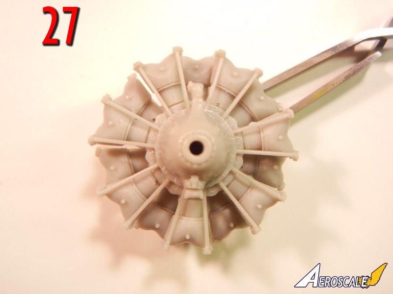
- Photo 27 shows the completed engine sans exhaust collectors.
lower wings
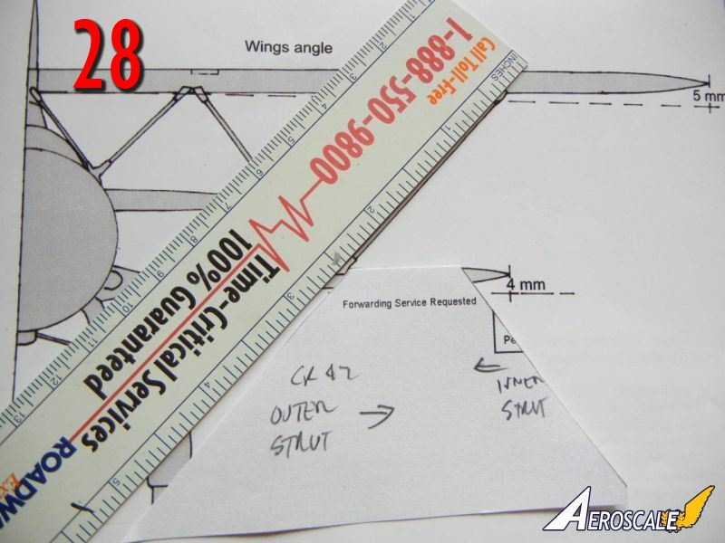
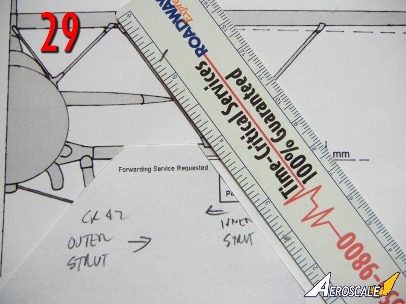
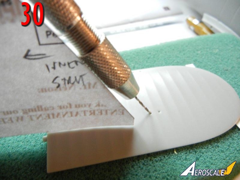
The lower wings have a metal rod inserted for strength, the remains of which can be used for attaching the lower wings to the fuselage. As mentioned in the fuselage section, I recommend drilling out the appropriate hole on each side of the fuselage attachment point to accept the entire metal rod.- Begin by drilling out the strut attachment holes in the lower wings as indicated by the small indents. You can drill these at the correct angle for the metal rod that sticks out of each end of the strut by simply transferring the angle from the plans onto a piece of cardboard or paper (see photos 28/29). Photo 30 shows the holes being drilled using the template. Note that they do not have to be perfect, as the brass rod in the struts will allow you to bend them a little to adjust their fit a little if needed.
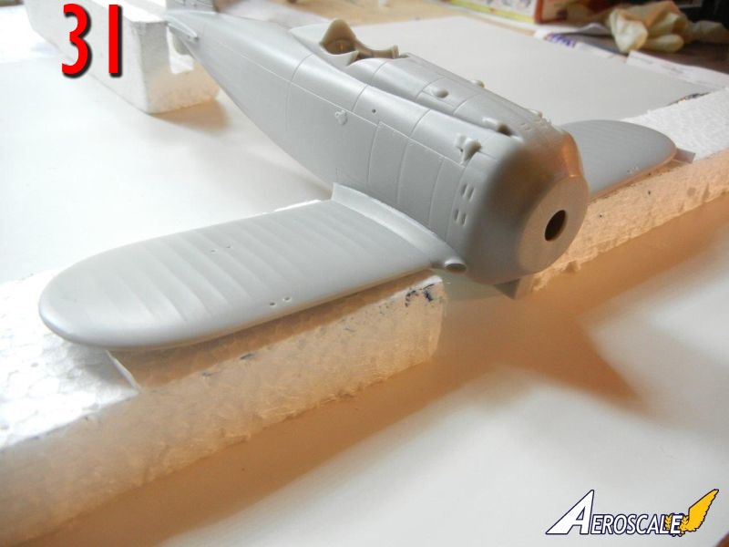
- Attach the wings to the completed fuselage assembly. Note the lower wings should have 4mm of dihedral at the tip according to page 6 of the instructions. I use a cardboard spacer to ensure the proper angle (see photo 31).
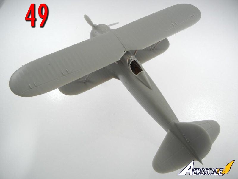
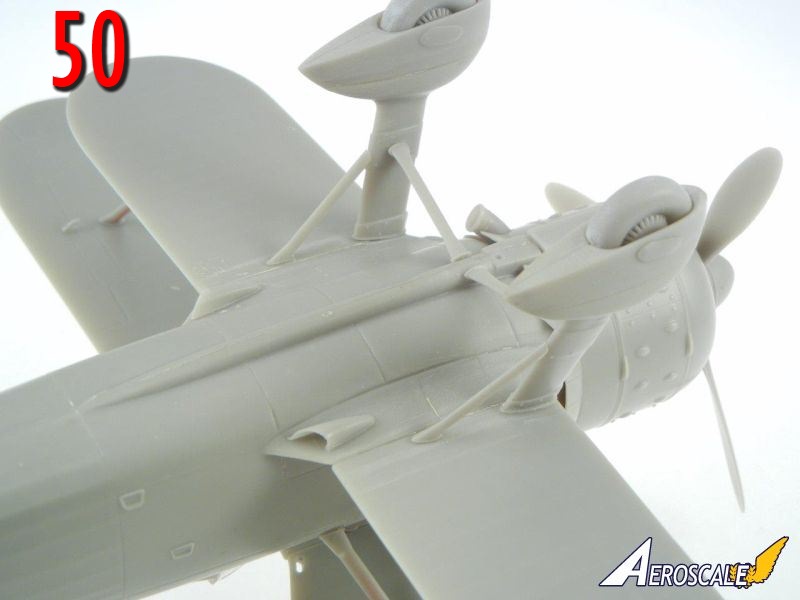
- Attach the two small scoops, one on the bottom of each wing (shown on page 9). See completed build photo 50 for placement.
empennage
The empennage is covered on page 9. Note that you can install these parts at any time after the fuselage is completed.- I began by attaching the vertical stabilizer to the fuselage
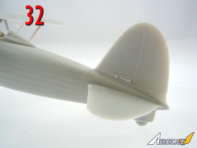
- I then attached the tail planes to the fuselage. Photos 32 shows the completed assembly. You can use the provided tail lamp, or I would recommend a piece of clear sprue for the tail lamp.
upper wings and wing attachment
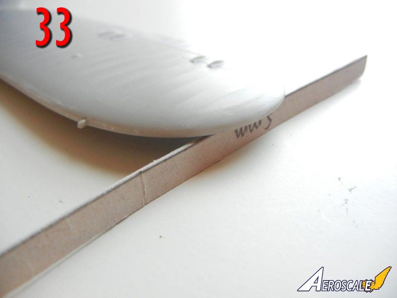
The upper wings should have 5mm of dihedral according to the instructions (page 11). As shown on page 10, you will need to join both upper wing halves to the center piece. As with the lower wings, I recommend you drill out the appropriate holes for the struts.- Test fit the upper wings together and check the dihedral, adjust as necessary. When satisfied, glue together using a spacer taped to the bottom of the wing tip (photo 33). Now for the "tricky part". With the more complicated strut design of these Italian fighters, I had to think for some time on what would be the best way to go about attaching the struts. In the end, I think I found an easy way to do it. It turns out we only really need the inner cabane struts (parts IX, X, XI and XII) and the inner interplane (parts III, IV, V, and VI) struts to provide strong enough support to attach the upper wing in place.
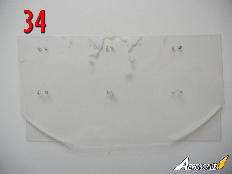
- I started by using a section of an old clear plastic pie cover to mark and drill holes to match the holes in the bottom of the wing (see photo 34). I then used this as an upper wing template in place of the upper wing to align the struts when attaching them to the lower wing and fuselage.
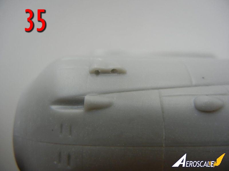
- Drill out holes for the inner cabane struts (parts IX, X, XI and XII) in the forward fuselage (see photo 35) and test fit the inner cabane struts using the clear wing template. I found I had to bend/push mine a bit to get them into the correct position.
- Test fit the inner interplane struts (parts III, IV, V, and VI) using the upper wing template to align them properly.
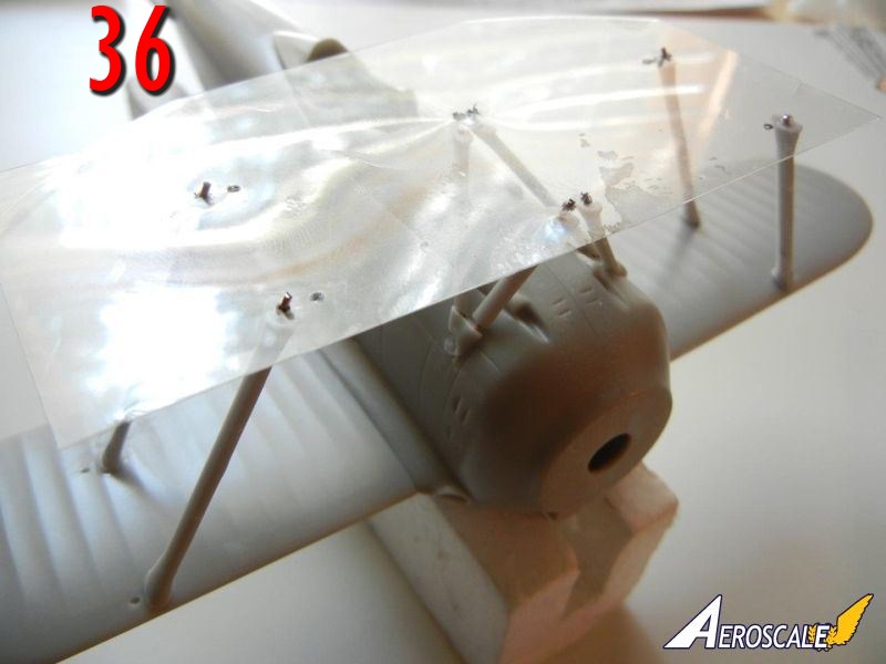
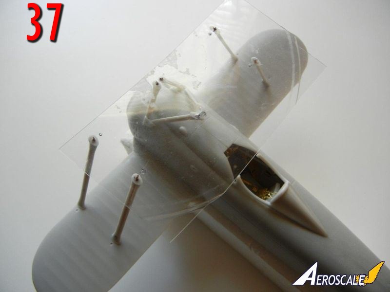
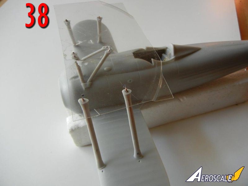
- When satisfied with the fit, glue the inner cabane and inner interplane struts in position, again keeping the clear template in place to hold the upper ends in position. It should look like photos 36-38. Note that the extra holes you see in the clear wing template are for the "N" shaped cabane struts, which it turns out are not needed for strength and can be added after the upper wing is glued in position.
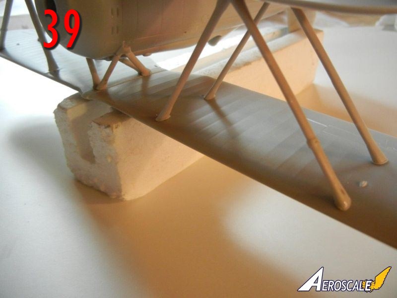
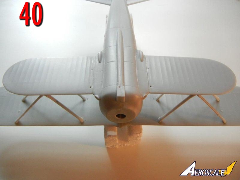
- Once dry, test fit the upper wing into position. Add the outer cabane struts (parts I, II, VII and VIII) and when satisfied, glue into position (photos 39/40).
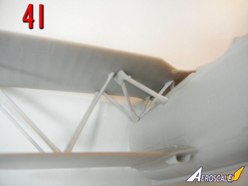
- Once dry, you can add the "N" struts into position (photo 41)
landing gear
The main gear struts are shown being assembled on page 4 of the instructions, and shown being attached on page 12- Glue the two fairing halves together for each spat as shown on page 4, trapping the wheels between them (be sure to read the two following notes before doing so).
- Note that the two parts labeled "I" go together, and the two parts labeled "II" go together. Do not fit "I" to "II".
- Also note that both wheels should have the hub detail facing the same way (with the fin detail on the port side of the aircraft).
- Attach the gear struts to the spat/wheel assemblies as shown on page 4 of the instructions. Some filling and sanding will be necessary to achieve an optimal fit.
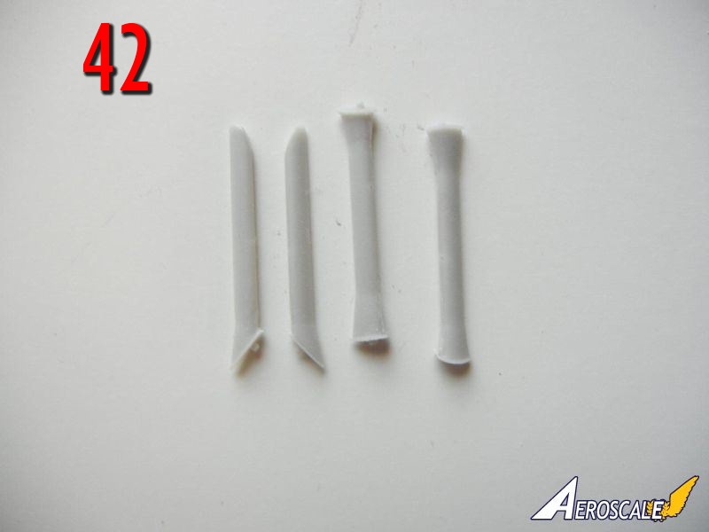
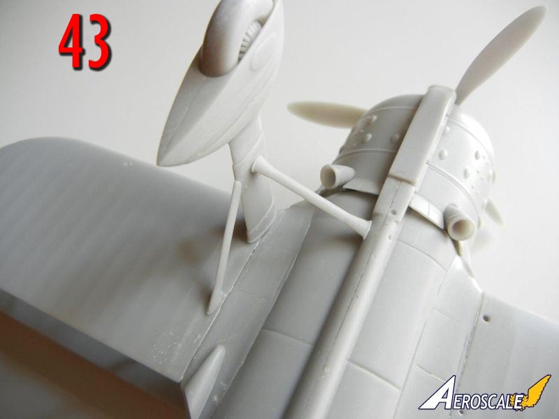
- When dry, attach to the underside of the aircraft using the gear support struts (photo 42) to align the gear in the correct position. Photo 43 shows the starboard side gear attached.
final assembly
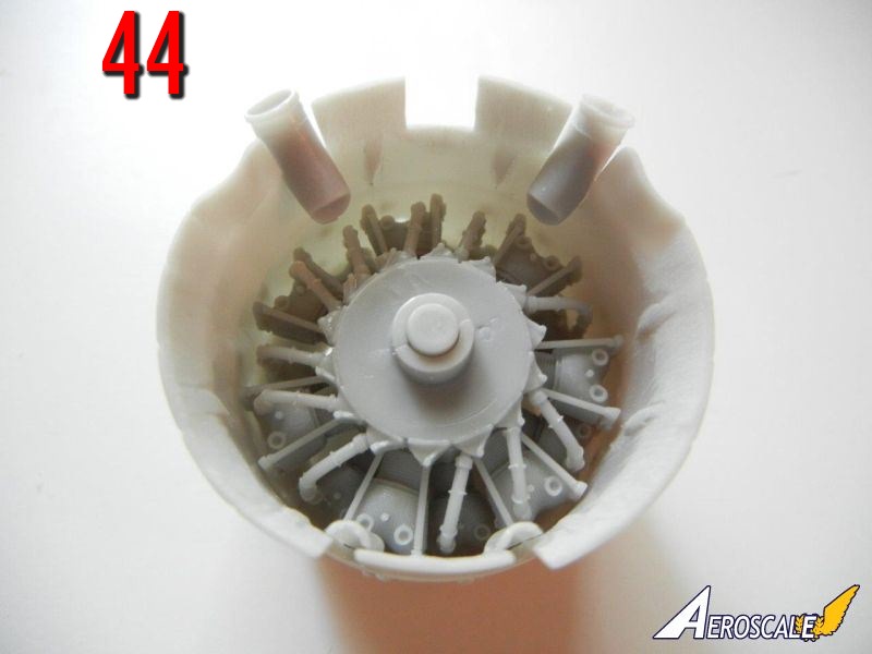
- Insert the engine into the cowling. I did not find it necessary to glue in place. Attach the gun troughs (shown on page 6) in place after placing the engine in the cowling. I glued the exhaust into place as shown on page 10. See photo 44. If using the night fighter exhaust, you can glue this into position after the engine/cowl assembly has been attached to the fuselage.
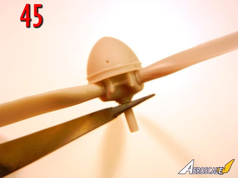
- Assemble the propeller as shown on page 11. Note that the spinner cap should rest on the prop hub as shown in photo 45.
- Attach the PE instrument cowl (after bending into shape), headrest, windscreen and venturi tube in position as shown on page 9 if you have not already done so.
- Attach the engine/cowl assembly to the fuselage. Add the appropriate chin scoop (shown on page 6) once the cowl is in the correct position.
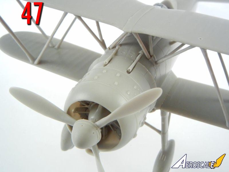
- Attach the two MG's to the fuselage as shown on page 12 (see finished photo 47)
- Attach the various control horns into position on the wings (page 12) and tail planes (page 11).
- Finally, attach the two pitot to the forward starboard interplane struts as shown on page 12.
conclusion
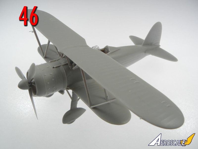
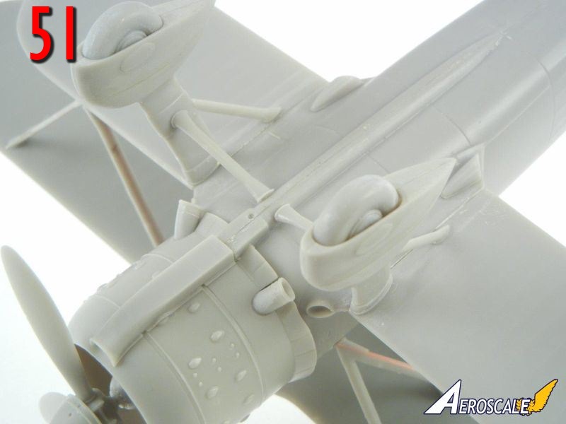
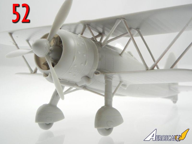
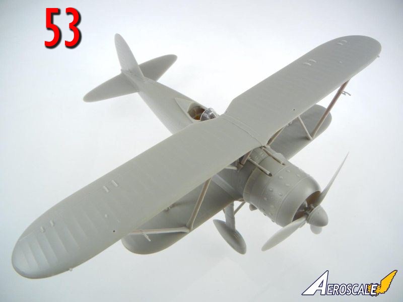
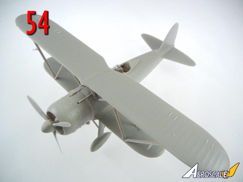
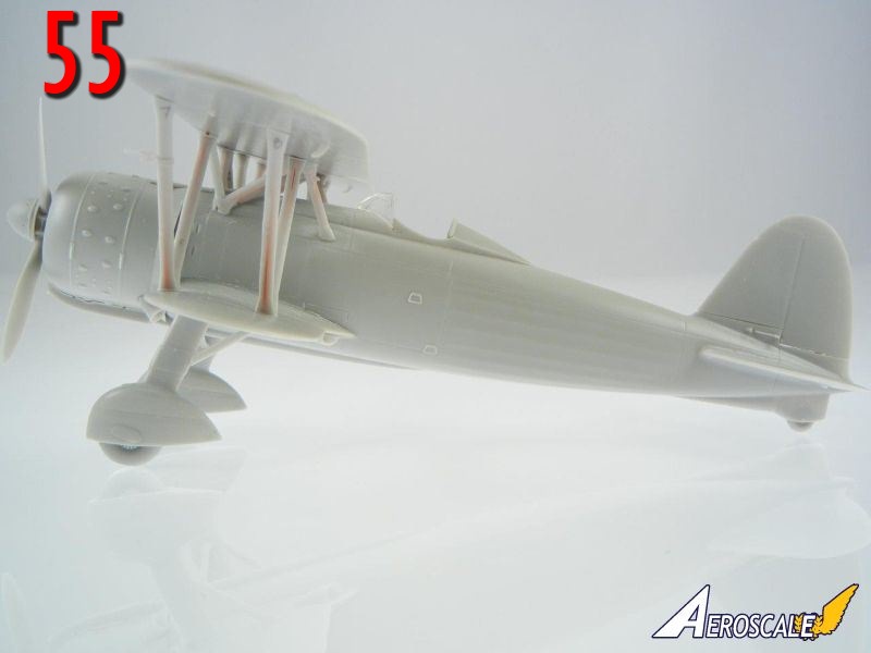
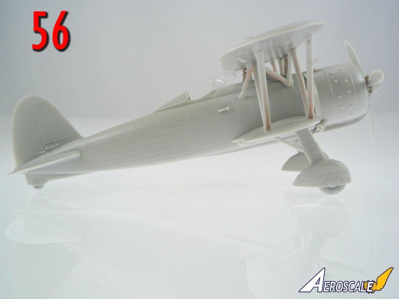
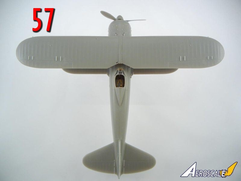
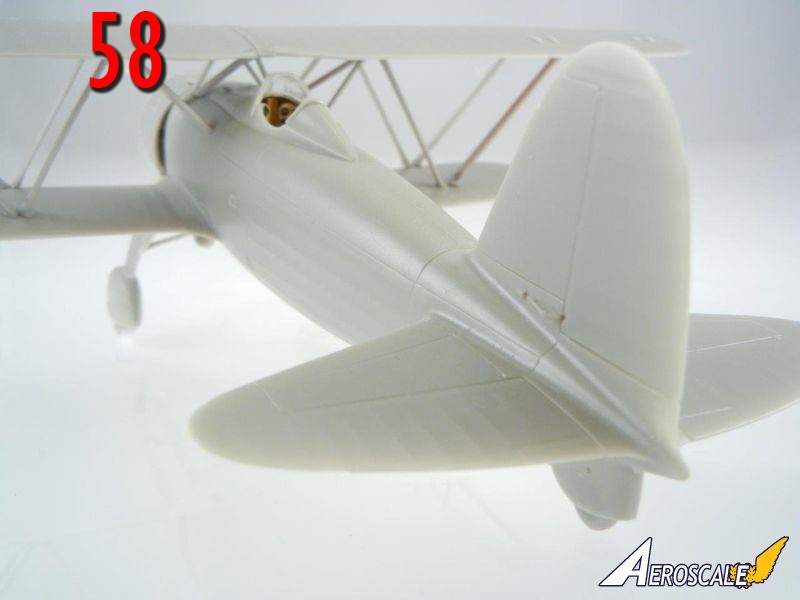
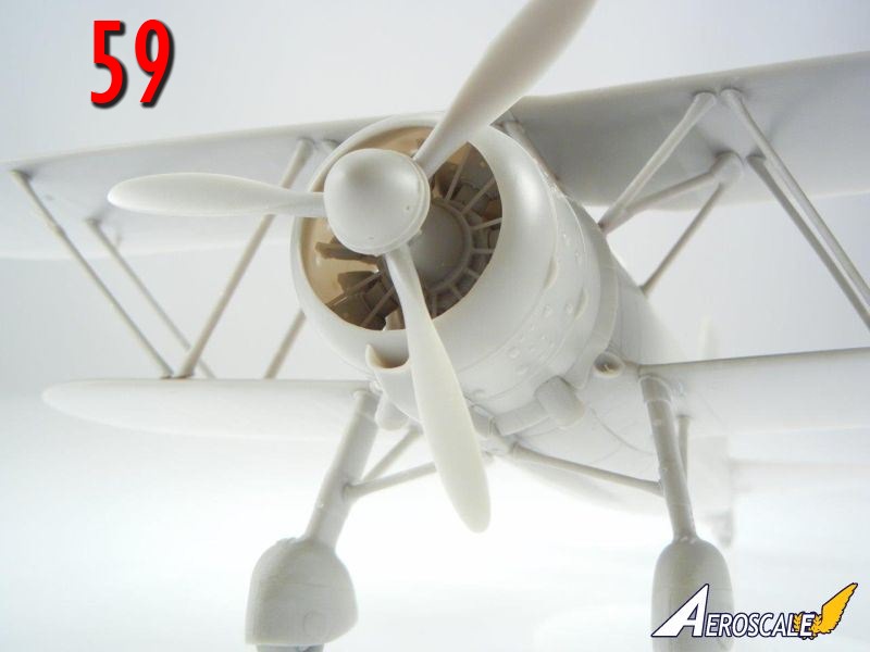
Congratulations on your newly finished model! Photos 46 ~ 59 are of the completed model.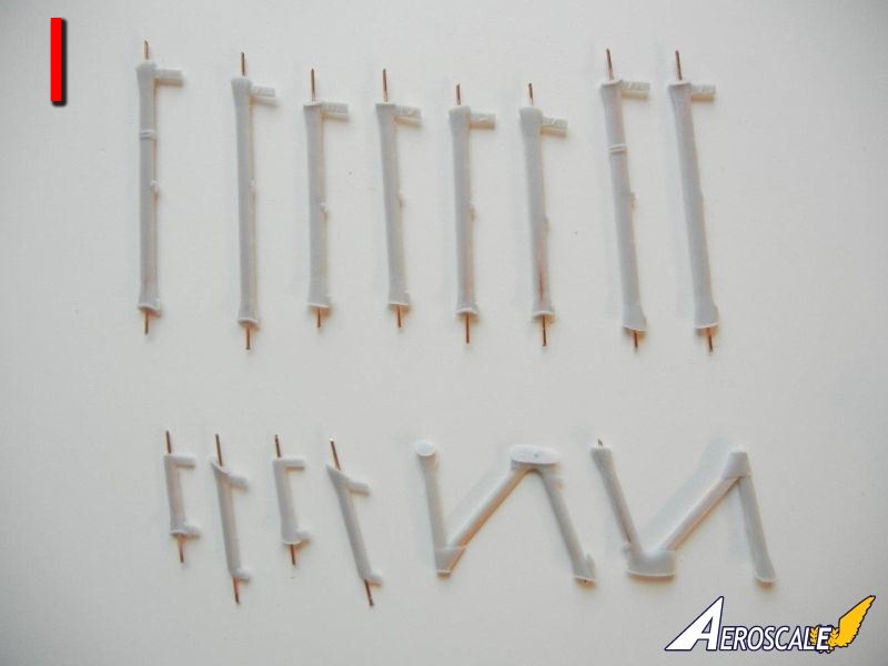

About the Author


FROM: GEORGIA, UNITED STATES
I've been modeling on and off for over 40 years. My primary interests are WW1, Interwar and WW2 aircraft, although I do build an occasional WW2 armour kit. I used to build 1/32 kits back in the 80's, but switched to 1/48 in the early 90's when all the nice new kits started showing up. I've sinc...
Comments
Copyright ©2021 by Doug Nelson. Images also by copyright holder unless otherwise noted. The views and opinions expressed herein are solely the views and opinions of the authors and/or contributors to this Web site and do not necessarily represent the views and/or opinions of AeroScale, KitMaker Network, or Silver Star Enterrpises. Images also by copyright holder unless otherwise noted. Opinions expressed are those of the author(s) and not necessarily those of AeroScale. All rights reserved. Originally published on: 2013-12-07 04:25:10. Unique Reads: 6033

WEB HOSTING BY


Copyright ©2021 AeroScale and Kitmaker Network, a subsidiary of Silver Star Enterprises
All Rights Reserved. Please read our Conditions of Use and Privacy Policy.
All Rights Reserved. Please read our Conditions of Use and Privacy Policy.