_GOTOBOTTOM
World War II: USA
Aircraft of the United States in WWII.
Hosted by Rowan Baylis
P-38E into an F4 Photo Lightning
Thearmorer
_VISITCOMMUNITY
Alabama, United States
Joined: June 17, 2014
KitMaker: 121 posts
AeroScale: 118 posts
Posted: Friday, February 06, 2015 - 08:09 AM UTC
Having gained some small measure of confidence by reasonably succeeding in my F4F to FM-2 conversion, and thus armed with a misguided sense of ability, I shall endeavor to tackle another long delayed conversion. This time the object of my machinations is the Academy/Minicraft 1/48 scale P-38E kit which I have visions of turning into a Lockheed F4 photo-recon version.

An artist's rendition of what is in the box.


This is not a bad kit in it's own right, as with most Academy kits this one is not without it's warts, but the detail and accuracy is good for a kit this age. It is a direct relative of the excellent P-38L build that Joel_W recently completed and I will refer the reader to that topic as an example of how it should be done. However my misguided meanderings will take me in this direction:


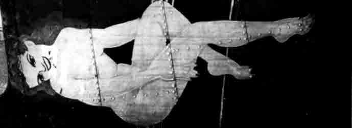
This shot upon close examination appears to be a colorized version of this b&w shot.


As with any colorized photo, all colors involved are suspect. This shot was probably taken in the summer or early fall of 1942 and shows an F4 of the 8th Photo Recon Sqdn. in the SW Pacific. This is the direction I am heading - and this is where I'm coming
from:


This is another one of my projects that got started long enough ago that I am no longer quite sure where it was originally headed. The two small resin pieces are the extent of the conversion. How hard could two little pieces of resin possibly be? For starts one has to remember that model conversions are like plumbing projects, one not only has to contend with the parts being replaced, but there is a near iron-clad certainty that any parts that come in contact with, or in near proximity of said parts will also require work. Thus we launch into the land of guess-work and supposition. The cockpit is the True Details P-38 set, which like most True Details cockpits has some fidelity shortcomings but is an improvement over most kit parts. This cockpit was done at a time when my standards were a bit more slack than at present so at some point in the build process I'll have to go back in and see if anything can be done to spruce it up without making a bigger mess. The only real conversion work done at this point is to saw off the bottom of the nose fairing to accept the resin ventral camera lens. The conversion pieces themselves are of unknown origin (something gathering dust on a LHS back shelf in the 1990's). The 3 inch x 3 inch instruction sheet (remember - how difficult can two small pieces of resin be?) mumbled something about these being for the Hasegawa Kit. This may explain the fit of the recon nose on the Academy forward fairing.


This is definitely heavy in the jowls and will take some work to get it smoothed out. More on this as our build develops.
Redhand
#522
_VISITCOMMUNITY
New Jersey, United States
Joined: January 20, 2013
KitMaker: 1,460 posts
AeroScale: 1,443 posts
Posted: Friday, February 06, 2015 - 06:47 PM UTC
You're a better man than I am, Gunga Din. That's going to be a helluva paint job, after the "east" work of the conversion. But I like the subject matter.
Joel_W
Staff MemberAssociate Editor
AUTOMODELER
_VISITCOMMUNITY
New York, United States
Joined: December 04, 2010
KitMaker: 11,666 posts
AeroScale: 7,410 posts
Posted: Friday, February 06, 2015 - 07:23 PM UTC
You can count on me tagging along for this conversion. Of course how can just two simple little pieces of resin be much of a conversion project? Well, just looking at the fit of the nose is a great hint, and I'm really curious to see how the bottom piece fits. I'm betting it's undersized as well.

So the major issue is that of the overall shape. Which is correct, the Academy or the conversion? I think both are close. Your photograph shows a lip/step or I think it does between the two, but it's a lot less then what you have in your dry fit. Also that side mounted camera position really looks like it was a Ad Hoc install.

I'm not the greatest when it comes to research, and make certain assumptions without fully documenting it. Case in point is the outside lower intakes on the engine cowlings. I just replaced them with home made larger dia ones. But in reality they're spark plug blast tubes, you might want to replace them with some brass tube.

I also replaced the kit cockpit which was pretty poor with a Legend cockpit. I was disappointed in it, and should have gone with the True Details one you used. The seat and brace assembly in my example were next to useless, and I ended up reworking the kit seat assembly. You might want to also consider replacing the turbos with AM resin ones from Quickboost which are a major upgrade. I would also suggest using the Ultra Cast wheels, and the Eduard masks for all that complex cockpit glass.

And Brian, I'm pretty sure that you're the 1st person to ever post any reference to "Gunga Din" in a online plastic modeling forum.

Joel
Redhand
#522
_VISITCOMMUNITY
New Jersey, United States
Joined: January 20, 2013
KitMaker: 1,460 posts
AeroScale: 1,443 posts
Posted: Friday, February 06, 2015 - 07:38 PM UTC

Quoted Text


And Brian, I'm pretty sure that you're the 1st person to ever post any reference to "Gunga Din" in a online plastic modeling forum.

Joel


WOR, Million Dollar Movie, the 1950s? Yeah, a different eon.


I have legal work this morning but am DEFINITELY returning to the 17 today.
Joel_W
Staff MemberAssociate Editor
AUTOMODELER
_VISITCOMMUNITY
New York, United States
Joined: December 04, 2010
KitMaker: 11,666 posts
AeroScale: 7,410 posts
Posted: Friday, February 06, 2015 - 07:51 PM UTC
BTW, just how close to the F4 paint and weathering are you going to be trying to replicate? I'm not exactly the world's greatest fan of beat up looking aircraft in model form. I much prefer the "Used but not Abused" look to an operational aircraft in miniature.
Joel
Joel_W
Staff MemberAssociate Editor
AUTOMODELER
_VISITCOMMUNITY
New York, United States
Joined: December 04, 2010
KitMaker: 11,666 posts
AeroScale: 7,410 posts
Posted: Friday, February 06, 2015 - 08:01 PM UTC

Quoted Text


Quoted Text


And Brian, I'm pretty sure that you're the 1st person to ever post any reference to "Gunga Din" in a online plastic modeling forum.

Joel


WOR, Million Dollar Movie, the 1950s? Yeah, a different eon.


I have legal work this morning but am DEFINITELY returning to the 17 today.


Brian,
You're certainly in rare form today. Better get back to the 17 before it starts to grow mold. Unfortunately for me, I'm working today 2-10ish, so there isn't any modeling for me today.

That's one great picture. I certainly remember watching that movie dozens of times. Of course today, not too many even know who Gunga Din was, nor so the movie.

Joel
Thearmorer
_VISITCOMMUNITY
Alabama, United States
Joined: June 17, 2014
KitMaker: 121 posts
AeroScale: 118 posts
Posted: Saturday, February 07, 2015 - 09:29 AM UTC
Ah yes, Kipling's quote is one that come frequently to mind at this site, I am more often than not amazed by the quality of the builds I see here. I too am old enough to have seen Gunga Din more than a couple of times, or The Three Feathers, there's a reference that ought to stump the masses. Sure, a lot of the old flicks were a little hokey by today's standards and they tended towards the melo-dramatic but there was a story in them worth watching. Now we get special effects and some banal dialog to give the overpaid actors something to do between chase scenes, some improvement (not). Now I'll get off the soap box and back to the build. Joel, I hear you on the tweaks to the engine nacelles but I'm kinda constrained on what I can do at this point. the following picts will show why.


What you see here is about a pound of fishing weights (I only exaggerate a little) crammed into each nacelle since I knew I might be a little challenged on getting it into the nose. I figured that's where the weight is on the real thing, it might work for me. There are baffles to prevent looking though the oil cooler ducts, but I just noticed that if one looks at just the right angle you can see in the front of one and out the rear of the opposite side, missed that one. Note to those keeping score at home, separate the two sides in some fashion if you do one of these Academy kits. This is a shot of the wheelwells and their good scale 6 inch (15 cm) thick sides on each side of the wheelwell. Destroyer armor ain't that thick! What you see here has been changed a bit since the photo was taken, this is what the directions tell you to do (I was just following orders). Also in this shot, and the main purpose of it is to show that most of the various vent openings will need a little file work to improve the scale thickness. The right has been done the left still needs work. This shot is the top of the wing showing the preliminary holes for the air intakes next to the superchargers, the rest of the work is some attention with a half-round needle file to shape and enlarge the intakes.


As you can see in this repeat shot, the intakes along the nacelles need the same treatment.


There is another option if you're not inclined to spend your time with a file making small holes big, Quickboost provides a set of supechargers and intakes for the P-38F which are probably close enough for the E-model. They weren't an option when I started this project, and besides, adversity builds character, and broadens your vocabulary.


I believe Joel recommended this update set, and it does seem to have it's merits. I'm not altogether sold on getting it at this point. I've already got reasonable intakes done, and I don't know if the supercharger is that much of an improvement over the kit version on the early P-38's. This is what you get in the kit, plus a little paint.


I did't get a good picture of the front of the intakes uploaded, but they are drilled out and look just about the same as the Quickboost version. I'll forge on here in a little bit, but I want to get this uploaded before I get timed out.


Thearmorer
_VISITCOMMUNITY
Alabama, United States
Joined: June 17, 2014
KitMaker: 121 posts
AeroScale: 118 posts
Posted: Saturday, February 07, 2015 - 09:44 AM UTC
Ooops, I just notices I must of missed a photo, the wheel wells - here it is:

Joel_W
Staff MemberAssociate Editor
AUTOMODELER
_VISITCOMMUNITY
New York, United States
Joined: December 04, 2010
KitMaker: 11,666 posts
AeroScale: 7,410 posts
Posted: Saturday, February 07, 2015 - 07:51 PM UTC
The right amount of weight was a major issue for me from day one. There was no way that I was going to have a tail sitter again. My GWH P-61A even with Terry Dean's weight set was a tail sitter if you walked by the display case. So I taped it up and figured out what I needed to add, then added a little more. All the weight I added went into the nose, none was needed in the engines. But it turned out I just made it.

As far as the two turbos go, the resin and kit parts are now a one piece affair. The resin ones are much more detailed especially around the exhaust area, and are a major upgrade to basically is very soft molding of the kit ones.


And yes they do give you new intakes, but I figured cleaning up the mess I'd make cutting off the kit ones wasn't worth the effort. I drilled the kit ones out, then using a larger dia drill followed by a rat tail file to the scoops to look paper thin. One thing I did screw up but didn't' realize it till after I had applied the Alcad is the drill bits ate into the plastic right in front of the intakes, and I needed to putty them in.

My biggest complaint about the kit is the horrendous wheel wells. Talk about poor engineering!!

I was also not to happy with the way that the boom glycol radiator vents looked, and decided to cut them out, and make new ones out of sheet, then glue them in a more open position with the actuating rods added.


On the finished P-38 they do add a certain little something extra.


Joel
Thearmorer
_VISITCOMMUNITY
Alabama, United States
Joined: June 17, 2014
KitMaker: 121 posts
AeroScale: 118 posts
Posted: Saturday, February 07, 2015 - 10:42 PM UTC
Joel, had I been thinking ahead (which I wasn't) your approach to the oil cooler outlets is the much more elegant solution, and really wouldn't add that much work. That approach would have also forced the issue of dealing with the crossover see-through effect, but at this stage of the game getting things in place inside would be a major hassle without breaking the booms apart, and that would be a bigger hassle. My approach will be to do some deeper engraving around the cooler flaps with some extra weathering to give the impression of a separate pieces.

Now to get into the meat of this conversion, dealing with the camera nose. These F4s were some of the first photo conversions of the P-38 type (late 1941 - early 1942) and Lockheed apparently took the same approach I'm taking, which is basically to take a stock P-38E and cut holes in it. No frills.


Based on experience, later models of the F4 and F5 recon Lightnings would get more refined camera apertures. The 8th Photo Recon Sqdrn and their aircraft shipped out for the SW Pacific in March, 1942. At this point in the war things were still pretty much going to Hell-in-a-handbasket for the Allies so these aircraft were needed yesterday type of situation, so no frills. Close examination of the photos indicates the camera openings are not symmetrical, the right side opening appears to be lower and further forward than on the left side relative to the angle of the nose bay access panel. This makes sense given the size of the recon cameras in use at the time. The P-38 nose is not that big, and to have two cameras back to back would be a bit tight. The openings themselves do appear to be the same size. After looking at several pictures and trying to judge the opening size relative to people and things nearby I guesstimate the size to be in the 14-16 inch (35-40 cm) range, and pretty square. 1 foot looks to small and 18 in. seems to large. Using my Murphy's rule scale i came up with openings about 6.5 mm square. Using a flexible drafting template I found a square about the right size and winged it on the locations.


Once I was satisfied with the placement I got an extra pair of hands (the wife) and used the same template to lightly scribe some more accurate lines to use for the actual cutting. With all these machinations, the two halves of the nose fairing re-split which made working on the openings a lot easier. The next step was to drill a fair sized hole in the middle of the proposed opening and go at it with a square jeweler's needle file until I got to my scribed lines.


At this point it was pretty obvious that I'd have to do something about the look in one side, out the other effect. My original concept was to just put a baffle between the two openings, paint it black (like the song, another geezer reference) and call it done. Upon reflection however, since the conversion pieces had molded camera lenses I figured maybe I might want to add some for consistency. Upon further reference checking it was a good choice. While the 8th PRS photos all seem to be just black squares, other shots clearly show the camera lenses. My solution was to cut a couple of short pieces of styrene tube, bevel the objective lens end and glue these to the baffle plate. The shape of the baffle plate was made by tracing the top of one half of the nose fairing to a piece of .03 styrene sheet for shape, and make it cover the opening inside the nose. It's glued at the top and the rear, which is also the front of the nose wheeelwell.


This is the whole thing stuck together:


So far it looks feasable. Now paint it black (60's music in the background), the baffle and nose interior is flat black and the camera lenses are gloss black just in case more will be visible than I think. Just to be on the safe side I put some white glue in the tubes to simulate the actual lenses. Well that didn't work out so good, when dry the white glue was still a little milky. I've used white glue in the past to make instrument lenses and the like with good results, but apparently Chinese glue is a different breed (ground Yak hooves, chicken beaks?) who knows. I popped that out and re-did the lenses with gloss coat finish, that did the trick.


An attempt to show the end result, yup it's black.


Now the acid test, to see if it works together!


So far I'm pleased, a few lumps and bumps to be smoothed out, but everything looks to be within tolerable limits. The opening glass is simulated using clear plastic packaging, of which I have an endless supply, compliments of over packaging, and filed to shape. It's held in place with white glue to prevent crazing the plastic, but there are strength issues with this approach. Time will tell.
Joel_W
Staff MemberAssociate Editor
AUTOMODELER
_VISITCOMMUNITY
New York, United States
Joined: December 04, 2010
KitMaker: 11,666 posts
AeroScale: 7,410 posts
Posted: Sunday, February 08, 2015 - 05:37 AM UTC
Talk about going the extra mile. Adding those cameras really kicks it up more then a notch or two. Well done.
Joel
Thearmorer
_VISITCOMMUNITY
Alabama, United States
Joined: June 17, 2014
KitMaker: 121 posts
AeroScale: 118 posts
Posted: Sunday, February 08, 2015 - 07:45 AM UTC
The next couple of shots are for the open panel people. These show the general layout of the camera equipment, unfortunately they are from the same angle so it's hard to get an idea of the right side. There are subtle differences between the two, but the general layout seems to remain the same.


With the preliminary cutting done it's now time to try to get all the pieces to fit together. To try and eliminate or at least seriously reduce the excess width in the Academy nose fairing I went after the front 1/8th of an inch or so with a router to thin it down some to gain a little flexibility in compressing it and I removed some from the narrow strip of original kit part left between the two resin pieces on the bottom of the nose. I also filed 6-8 notches along the inner leading edge of the kit part, again hoping to make it a little more flexible. The resin parts are fixed in place using 5-minute epoxy, which I mixed up and dutifully stood holding for 15-20 minutes to get a good setup. Even after all that I still had a slight step to deal with. This is where I ended up:


The white stuff is milliput putty that I used to hopefully blend everything in. I also filled in the 2 gun ports and corresponding shell ejection chutes on the bottom. Apparently some F4s retained two guns for self-defense. None of the 8th PRS planes I saw in the photos had this feature. Given the distances flown in the Pacific, I suspect every ounce counted towards endurance. Now that I've got the photo nose pretty much in one piece I figure I'd best check and see how I'm doing in the weight and balance department before I attach the nose. The landing gear struts can be placed in the wheelwells in a reasonably secure fashion, so in they go to see how this is all going to sit with my 2 pounds of lead in the cowlings. Here she sits:


I don't know how well the struts will hold up in the long haul, but she sure sits pretty now. I spent quite a bit of time when I was fitting the bottom resin piece trying to get the rear of the resin to line up with the angle of the kit nose, but as you can see in the photo there's still a bit of a step in the lower portion of the nose. More file work and fitting is in order. Finally got it down to this point and declared victory.


Not bad, but now I've still got a slight step between the corrected nose and the cockpit portion.


Remember the fragile camera windows? Yup those puppies are right next to the panel lines I've got to smooth out. Well, I can't apply my usual hack and slash approach to seam sanding, as is my wont, in this situation. If I pop one of the windows with everything together (particularly if the window pops in instead of out) I don't have a good plan "B". Thus the tape on tape covering tape that you see here, to try and limit the milliput overflow. After much concern over where fingers were and a dainty touch that even the students at Miss Prudence's School for Proper Young Ladies would be proud of, I got to this point.


The next hurdle will be to see what this looks like under a coat of primer.

This shot was one of the primary references I used to try and determine the size of the camera windows. Using normal sizes for heads and arms, I came up with an opening around 15 inches square. When adjusted for scale and applied they look about right.


Next I'll delve into the wheelwells.
Joel_W
Staff MemberAssociate Editor
AUTOMODELER
_VISITCOMMUNITY
New York, United States
Joined: December 04, 2010
KitMaker: 11,666 posts
AeroScale: 7,410 posts
Posted: Sunday, February 08, 2015 - 08:41 PM UTC
I'm dully impressed with how you got the resin to and nose section to blend. One just can't expect it to be a perfect fit no matter how much effort has gone into it.

As a back up plan if you accidently pop a window, could be Micro Krystal Kleer. Back in the good old days, we used it for windows of all sizes in 1/72 scale. Just not sure if it could bridge a window opening that big. the only other alternative is to carefully cut out a new window that just fits on top of the framing.
Joel
Redhand
#522
_VISITCOMMUNITY
New Jersey, United States
Joined: January 20, 2013
KitMaker: 1,460 posts
AeroScale: 1,443 posts
Posted: Sunday, February 08, 2015 - 10:37 PM UTC
Just amazed how fast you "get on with it," compared to my snail's pace. Lookin good, too. I like these ambitious conversions of yours.
Thearmorer
_VISITCOMMUNITY
Alabama, United States
Joined: June 17, 2014
KitMaker: 121 posts
AeroScale: 118 posts
Posted: Tuesday, February 10, 2015 - 04:02 AM UTC
Having gotten the photo nose flogged into some level of submission I now need to turn my attention to the hideous landing gear wells. Looking back a few frames, this is what I started with:


An exceedingly blah chromate green box with an elbow in it, as per kit instructions. I my search for info on camera window placement I came upon this little gem.


It was epiphany time once more. That nose gear door looks very much like slightly weathered bare aluminum. One can just barely make out a small portion of the wheelwell just above the aft section of the door, and it looks to be the same way. I have seen other photos which clearly show other photo Lightnings with zinc chromate green wheelwells and gear doors but the 8th PRS shots, as best as I can determine all had bare metal wells. Given the time frame these aircraft were put into service, late 1941-early 1942, time and materials were all in short supply. I can readily see a decision made to skip on the interior finishing. This means everything gets a new paint job. After a good dose of Floquil's Old Silver it's time to actually figure out what I'm going to do in there. Trying to find any photo evidence of early P-38 wheelwells is similar to embarking on a quest for hen's teeth. The restored early P-38 "Glacier Girl" sprang to mind, hoping someone kept a photo record of the restoration, a lot of photos of the aircraft in flight etc. but not a wheelwell to be found. I ended up settling on these photos of a restored later model P-38 on the Cybermodeler site.


This is my work collage of individual photos from the site. (disregard the instrument panel in the background, that's a different story) The big blue thing is a pipe connecting the engine to the radiators in the boom behind the wheelwell, and a version of this is included in the kit (see Joel_W's P-38 build). Since this is a restoration, I suspect the blue color was not on the original, or at least that's the tact I took. The same goes for the anodized blue hydraulic fittings. They look sharp in the gray wheelwell, but I've got it in my head from my previous life in aircraft maintenance, that these wouldn't have appeared before the late 1050's. If there's any hardware historians out there that have any insight into this tempest in a teapot, I'd appreciate a heads-up. The chromate green duct to the supercharger (I think) could also be a restoration artifact, but it's also possible due to different subcontractors, replacement parts etc. that some (many?) in-service aircraft could have had the same feature. I liked it, and since the wheelwell's were previously chromate green, I kept it. The black box thingies under the coolant pipe appear to be electro-mechanical and electric fiberglas junction boxes. These looked prominent enough to me to be kept, so I fabricated something that looked a little like those out of two 40 thou. styrene sheets glued together and filed to shape. The bottom mosaic is the nose wheelwell. The Academy kit boxed off the aft end of the nose well (fortunately) thus saving me the unenviable chore of trying to replicate that rat's nest. With the exception of some hydraulic lines running along the sides there isn't much to see in the nose well. Academy molded some token lines and fittings into the nose well roof and let it go at that.


I threw in a burnt umber/black mix wash to highlight the lines a little, and painted the fittings a dark metallic gray and let it ride, at least for now.

The main landing gear well were busy enough to warrant a little extra work, plus my anal retentivness re-certification is about to lapse anyway so I though I'd add some stuff. These are the primary tools required:


I figured I'd use some 24 and 28 gauge craft wire for some of the hydraulic lines in the well. The first order of business was to draw out the rough dimensions of the kit wheelwell and where some of the prominent features fell within it. I used this to make a jig to help me make the bends in the wire to correspond to the hydraulic lines.


The little black things are a couple of the styrene junction boxes with a few strands of "extremely" fine copper wire braided and later given a coat of very thinned white paint to represent the wire bundle. The initial fitting:


That large pipe from the radiators had a rather prominent flexible collar on it that was not on the kit part. Since it sits up (down?) near the bottom of the wheel well I decided to add it. The flexible rubber part is masking tape and NATO black
paint. The "O" clamps are 28 ga. craft wire squeezed with a pair of flat jaw duck-bill pliers to flatten them a little, and partially wrapped around some needle nose pliers to shape. Then put over the tape and crimped down.


The craft wire hydraulic lines were bent to shape and then cut to length by trial and error. The rest was supper glue and tweezer work, enhanced with a hearty expansion of my more descriptive vocabulary.


Next that pesky yellow O 2 bottle.
Joel_W
Staff MemberAssociate Editor
AUTOMODELER
_VISITCOMMUNITY
New York, United States
Joined: December 04, 2010
KitMaker: 11,666 posts
AeroScale: 7,410 posts
Posted: Tuesday, February 10, 2015 - 08:02 PM UTC
I'm really impressed at the level of detail your wheel wells are achieving. I kind of just did enough to busy them up some. I did opt for GZC over the Aluminum, as it was a choice based on all the pictures had being 50/50 one way or the other.

The large Glycol pipe certainly was Aluminum and not blue as you see on the few restored aircraft. I also made the rubber joiner cups out of tape and painted black, but I couldn't come up with decent looking clamps. Your method of flattened wire is simple to duplicate, and work time after time. Thank you for sharing that with us.

Your wheels already look 100% better then the kit offering with all those wiring and details.
Joel
Redhand
#522
_VISITCOMMUNITY
New Jersey, United States
Joined: January 20, 2013
KitMaker: 1,460 posts
AeroScale: 1,443 posts
Posted: Tuesday, February 10, 2015 - 08:17 PM UTC
Damned impressive if ya ask me.
thegirl
_VISITCOMMUNITY
Alberta, Canada
Joined: January 19, 2008
KitMaker: 6,743 posts
AeroScale: 6,151 posts
Posted: Thursday, February 12, 2015 - 05:36 AM UTC
Nice detail work and on the nose


Terri
Thearmorer
_VISITCOMMUNITY
Alabama, United States
Joined: June 17, 2014
KitMaker: 121 posts
AeroScale: 118 posts
Posted: Saturday, February 21, 2015 - 04:26 AM UTC
Due to the weather, plus sum and sundry other malfunctions, it's been quite a few days since I've managed an update. It's been so cold in the dungeon that even the stash-rats left (caught a bus to Arizona I think). Before we leave the wheelwells for the topside, I figured I'd put in a couple of Oxygen bottles in. Based on the Cybermodeler P-38 reference photos there was one located in the top rear of at least one wheelwell. The reference photos are of a later model P-38, and a restored one at that, so the bottle may or may not have been there on the F4. A cut-away drawing I saw indicated there were yellow oxygen bottles aft of the wheelwells and forward of the coolant radiators in the boom and some unidentifiable green bottle in the same general area as the Cybermodeler photos. Neither reference is very definitive for an early F4, but I figured it would add a little clutter and color to the wells. I also made an assumption that such a thing would be symmetrical and put one in each wheelwell. This led me to my next problem, I needed a small oxygen bottle shaped object. After a search through all of the usual suspect areas, I found it was a case of "Goldilocks and the two bears". But wait you say, wasn't it Goldilocks and the three bears? Yup, in Goldilocks' case (she lucked out) one was too big, one was too small, and one was just right! I my case the "just right" bear didn't show. This was my attempt at a solution:


What we have here are a couple of the Quickboost bottle sets which I keep around for just such contingencies. But as is often the case, one's too long, one's too fat, and one's too small (or so I thought). My solution was to cut a couple of pieces of styrene tubing to length and fill them to overflowing with Milliput epoxy. I then rolled them between my finger and the mat to get the excess epoxy the same diameter as the tube and trimmed and shaped the ends with my finger to get a rounded shape. The result is passable in most instances where the bottle will not be overly obvious. I found this is a trick worth keeping in the bag of tricks, only a word of caution, let the epoxy cure fully, it still sands well and will not break. This is not the case with partially cured epoxy. In the end, I used the small 1/72nd walk-around bottles from the Quickboost set, the ones I made were too large, due primarily to the Academy kit wheelwells being significantly too small (those super thick wheelwell walls again). This is the result:


And with a little dark wash to highlight things a little:


Busy enough for me. Especially since no one is going to see it once the thing gets flipped over anyway. Onward and upward!
Joel_W
Staff MemberAssociate Editor
AUTOMODELER
_VISITCOMMUNITY
New York, United States
Joined: December 04, 2010
KitMaker: 11,666 posts
AeroScale: 7,410 posts
Posted: Saturday, February 21, 2015 - 09:47 PM UTC
I actually like your wheel well detailing as it looks way better then my really crude effort. I just wanted to get done with them, and then forget them as my focus was on my very 1st NMF.

In your last pictured of the bottom I noticed that you haven't addressed the three Recognition Lights. Do you have a plan for them?
Joel
Thearmorer
_VISITCOMMUNITY
Alabama, United States
Joined: June 17, 2014
KitMaker: 121 posts
AeroScale: 118 posts
Posted: Saturday, February 21, 2015 - 10:58 PM UTC
Joel, I hadn't given them a lot of thought until a couple of nights ago and at that point I figured I'd give them my semi-standard approach to fuselage lighting, which is, I'll try and put a center punch mark in each light circle using a needle in a pin-vise and then make a concave depression in each with an appropriate sized drill bit or circular burr. I'll then paint the depression with my new go-to light backing color - steel. The last step will be to fill the depression with the applicable Tamiya clear color. Sounds good in theory.
Joel_W
Staff MemberAssociate Editor
AUTOMODELER
_VISITCOMMUNITY
New York, United States
Joined: December 04, 2010
KitMaker: 11,666 posts
AeroScale: 7,410 posts
Posted: Sunday, February 22, 2015 - 12:58 AM UTC

Quoted Text

Joel, I hadn't given them a lot of thought until a couple of nights ago and at that point I figured I'd give them my semi-standard approach to fuselage lighting, which is, I'll try and put a center punch mark in each light circle using a needle in a pin-vise and then make a concave depression in each with an appropriate sized drill bit or circular burr. I'll then paint the depression with my new go-to light backing color - steel. The last step will be to fill the depression with the applicable Tamiya clear color. Sounds good in theory.


That's basically how I do it. The trick is to actually get the punch and then the drill bit in the center. That's where I screw up most of the time.
Joel
Redhand
#522
_VISITCOMMUNITY
New Jersey, United States
Joined: January 20, 2013
KitMaker: 1,460 posts
AeroScale: 1,443 posts
Posted: Sunday, February 22, 2015 - 01:27 AM UTC
I have gotten "acceptable" results using a punch on a sheet of aluminum foil, creating circles the size of the lenses, gluig them with thin white glue to the light surface, then covering that with a light swipe of the "clear" color.
chris1
_VISITCOMMUNITY
Auckland, New Zealand
Joined: October 25, 2005
KitMaker: 949 posts
AeroScale: 493 posts
Posted: Sunday, February 22, 2015 - 01:58 AM UTC
Hi there,
Only just stumbled on this thread . I'm following along now.
The Academy P38 is on my to buy list,need to find a job first.

I have a confession to make.and don't laugh,it wasn't the build that caught my eye it was the Brooks running shoe logo.
One a runner always a runner.


Chris
Thearmorer
_VISITCOMMUNITY
Alabama, United States
Joined: June 17, 2014
KitMaker: 121 posts
AeroScale: 118 posts
Posted: Sunday, February 22, 2015 - 02:15 AM UTC
Joel, I hear you on the centering issue, I've missed a few over the years myself. That's why the needle centering tool. I put the point where I think it should be and then move the pin vise holder around with the point as a pivot to see if it looks like a good center. When working with objects that close to the Mark 1.5 eyeball, the parallax issue gets pretty big. I use this method to drill out machine gun barrels, and get more hits than misses. It's not uncommon for me to move the "center" more than once before I'm happy. Brian, I'm assuming your using one of those pin-punch sets? My current solution to the little disk problem is one of those rotary leather punch tools. It doesn't always produce the best of disks (and virtually useless for holes) but it has two major virtues; one, it's cheap, and two, it's on-hand. It is also too crude to reliably punch disks in something as thin as alum. foil. The next part falls under the eye-of-the-beholder category, I went with the steel color in an attempt to darken the color background while still trying to simulate a reflective metal backing. However if I can figure out how to create reliable foil disks, your approach sounds good for landing lights and such.
 _GOTOTOP