_GOTOBOTTOM
World War II
Discuss WWII and the era directly before and after the war from 1935-1949.
Hosted by Rowan Baylis
FRROM 1/32 IAR-81C Build Review
DougN1
_VISITCOMMUNITY
Georgia, United States
Joined: August 08, 2011
KitMaker: 410 posts
AeroScale: 409 posts
Posted: Friday, July 04, 2014 - 04:04 AM UTC
Following hot on the heels of Rowan's Review I'm starting the build review of this new kit!

I've been waiting anxiously for this kit ever since it was first announced. Taking a look at the sprues, this kit is certainly an improvement over other MPM/Azur/Special Hobby kits and worth the wait. I understand from a Romanian modeling forum that at least part of the delay was due to new/better information/plans becoming available, which the manufacturer used to correct the kit to make it as accurate as possible. I for one applaud them for these efforts!

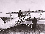
Unfortunately, as "the most famous fighter you never heard of" references for this aircraft are very few indeed. I've been able to collect these two, which I will be using for this build:


If I had to pick one, it would be Radu's book on the right, as it is in English, and has more updated and detailed information than the one on the left. Unfortunately, as there are no surviving airframes (I understand the two in museums are replicas) detail photos of things like the cockpit are quire rare.

I won't post photos of the sprues, as Rowan's review already has that. Instead, I'll jump straight into the build!

As a limited-run kit, almost all the parts have heavier than "normal" sprue attachment points and on my kit, the cockpit parts all seem to have a noticeable mold line that needs to be cleaned up as well. While this takes a little more time in parts clean-up, the end result is still a nicely detailed part that fits well.

While I plan to keep this build as close to OOB as possible, I could not resist adding the cables to the control column, as these are a prominent and visible feature in the cockpit. The kit part has the attachment points and couplings molded on, so I just drilled these out and added some wire, and used aluminum tape to make the bracket that secures them to the control column:


One thing to note. The kit provides two map cases (parts D34/D35 for those of you following along in your instructions). However, the real aircraft seems to only have one on the left side. Unless the pilot of your model needed an extra map case, I would leave part D35 off.

I assembled as much of the cockpit as I could, which still being able to easily paint it. Here are some photos of the completed cockpit subassemblies, which are now ready for paint:


The eagle-eyed amongst you may note that the rudder bar is slightly off set, as I like to have my rudders offset to the right, I always make sure that the rudder bar/peddles reflect that position

I also put most of the parts on to the fuselage sidewalls, omitting only parts that need to be painted separately:


On an unrelated note - I was recently told about his product by a friend:


This is Tamiya's thick liquid cement. It works great for attaching small parts! It goes on like a blob of superglue, but works like standard liquid cement. It looks like it will also be useful for attaching poor-fitting parts with gaps. I've used it on this build and it will be my "go-to" glue for attaching small parts on future builds - highly recommended!

That's all for now!

Comments/critique/questions always welcomed!

Doug
Joel_W
Staff MemberAssociate Editor
AUTOMODELER
_VISITCOMMUNITY
New York, United States
Joined: December 04, 2010
KitMaker: 11,666 posts
AeroScale: 7,410 posts
Posted: Friday, July 04, 2014 - 06:27 AM UTC
Doug,
I'll be following along with great interest, as I have a Special Hobbies limited run multi media kit of the F2A-# Buffalo in looking forward to building.

Your detailing of the control column really looks quite good.

I've been using Tamiya Orange top liquid cement for years. It's perfect for not so great fitting parts, or where you need precise glue control. One disadvantage is that it dries almost as fast as Extra Thin, making its use for gluing major assemblies like fuselages, and wings not a realistic option.

Joel
Merlin
Staff MemberSenior Editor
AEROSCALE
#017
_VISITCOMMUNITY
United Kingdom
Joined: June 11, 2003
KitMaker: 17,582 posts
AeroScale: 12,795 posts
Posted: Friday, July 04, 2014 - 09:26 PM UTC
Hi Doug

Nice start as expected. I've never seen any Tamiya cements in my usual UK shops or online sites, but they seem to be a good price on eBay, so I might give them a try. Thanks for the heads up.

All the best

Rowan
Holdfast
Staff MemberPresident
IPMS-UK KITMAKER BRANCH
#056
_VISITCOMMUNITY
England - South West, United Kingdom
Joined: September 30, 2002
KitMaker: 8,581 posts
AeroScale: 4,913 posts
Posted: Friday, July 04, 2014 - 10:41 PM UTC
I have one of these on order so I am following along Doug
DougN1
_VISITCOMMUNITY
Georgia, United States
Joined: August 08, 2011
KitMaker: 410 posts
AeroScale: 409 posts
Posted: Monday, July 07, 2014 - 08:28 AM UTC
Thanks guys - I appreciate you following along and your kind words

While reviewing my reference (Radu's book) and reading about the kit on other forums, I found out that the kit does have some minor accuracy issues I wanted to post about, as thisw build blog is intended to be a review build.

On the starboard fuselage sidewall, there is a box molded on that is a "breathing mask storage box" that is appropriate for the IAR-80, but not cannon armed aircraft like the IAR-81C. Instead, it should be removed, and replaced with an additional circuit-breaker panel. Ammo counters for the wing guns should also be added. The poorly edited (by me) photo below hopefully illustrates this point:


There should also be a "wing bomb carrier distributor box" marked in black on the edited photo above. Finally, there should also be an "injection pump (choke) on the forward part of this sidewall as well, but it is not included in the kit (it may not be visible once the cockpit decking is installed in all fairness).

I highly recommend obtaining a copy of Radu Brinzan's book on the IAR80/81 shown above, as it has very good line drawings, etc. that better illustrate the point(s) above and show what the missing parts should look like.

I thought about it for the past few days, and decided not to make the corrections outlined above on this build. However, as mentioned, I did want to document them for anyone interested.

More progress soon

Thanks for looking! Comments/questions/critique always welcomed!

Doug
Joel_W
Staff MemberAssociate Editor
AUTOMODELER
_VISITCOMMUNITY
New York, United States
Joined: December 04, 2010
KitMaker: 11,666 posts
AeroScale: 7,410 posts
Posted: Monday, July 07, 2014 - 10:48 AM UTC
Doug,
How different is the circuit breaker box from the mask box? If it's close, why not just fabricate it out of sheet plastic? I would think that quite a bit of the cockpit would be visible in 1/32 scale.
Joel
Merlin
Staff MemberSenior Editor
AEROSCALE
#017
_VISITCOMMUNITY
United Kingdom
Joined: June 11, 2003
KitMaker: 17,582 posts
AeroScale: 12,795 posts
Posted: Monday, July 07, 2014 - 06:39 PM UTC
Hi Doug

Nice catch. I'd have probably missed that one tucked away in the "systems" section of Radu's book (as against the main cockpit chapter). It looks like Icaerodesign slipped up there too in their 1:48 kit.

All the best

Rowan
DougN1
_VISITCOMMUNITY
Georgia, United States
Joined: August 08, 2011
KitMaker: 410 posts
AeroScale: 409 posts
Posted: Tuesday, July 08, 2014 - 05:22 AM UTC
@ Rowan - yes I just checked my Icaerodesign 1/48 kit and it is indeed the same with the O2 mask storage and not the circuit breakers in that spot, and it too is missing the ammo counter and extra bomb panel that the 81C should have. We'll have to keep ChukW away from this build as he missed it in his as well

@ Joel - the real issue is that the 02 mask storage box is molded to the sidewall, so I would have to replicate some of the stringer detail if I removed it. Since the circuit breakers are facing up at about a 40 degree angle with a support frame from the outside edge back to the fuselage, it would not cover up the missing/damaged stringer section.

I can certainly attempt to correct the sidewall and add in the appropriate details (circuit breaker panel, bomb switch box, ammo counter, choke) to the starboard sidewall, and maybe an 02 hose on the port side. But, that may slow down the build a bit

Since this is a review build, I'll put it to the readers. Please vote on one of the following options:

A) Press on - it's a review build, and I want to see how the whole kit goes together without extra detailing.

B) Fix it - now that we know about it, we want to see your modeling skills in action as you fix it so we can fix ours too.

I'd really like to see at least 10 total votes before we move forward with either A or B

I await your decision dear Aeroscalers!

Thanks!

Doug
Joel_W
Staff MemberAssociate Editor
AUTOMODELER
_VISITCOMMUNITY
New York, United States
Joined: December 04, 2010
KitMaker: 11,666 posts
AeroScale: 7,410 posts
Posted: Tuesday, July 08, 2014 - 06:27 AM UTC
Doug,
I'm voting for A. I didn't realize that there was that much additional work required to remove that box. And like you said, it's review/personal build, not a full blown contest model.
Joel
DougN1
_VISITCOMMUNITY
Georgia, United States
Joined: August 08, 2011
KitMaker: 410 posts
AeroScale: 409 posts
Posted: Tuesday, July 08, 2014 - 10:46 AM UTC
Joel, even if it were a contest model, no IPMS contest I've ever been to awards any points for accuracy

Now that we've identified the areas of inaccuracy, if readers want to see how to potentially fix it, I've no problem trying to do so. I just want to make sure that I do the best I can to give readers what they want to see in this review build!

I've edited the choice descriptions as I don't know that my sense of humor came through well Feel free to change your vote if you want to now Joel

Now lets see some more votes! I know Joel isn't the only one reading this build review

Doug
Merlin
Staff MemberSenior Editor
AEROSCALE
#017
_VISITCOMMUNITY
United Kingdom
Joined: June 11, 2003
KitMaker: 17,582 posts
AeroScale: 12,795 posts
Posted: Tuesday, July 08, 2014 - 06:27 PM UTC
Hi Doug

If you're like me, now you've spotted the problem it'll niggle at you if you leave it unfixed. As the circuit breakers and mount will largely hide the area previously occupied by the oxygen mask holder (viewed from above, at least), I think you probably can get away without totally restoring the sidewall detail if you don't want to get bogged down.

I know you began by declaring the build would be largely OOB, but I'd say go for it because your blog will be a point of reference for many people tackling the kit, so such fixes will be very useful.

Looking at Radu's drawings, there's a different lever evident too - was the style of the seat adjuster also changed?

All the best

Rowan
Joel_W
Staff MemberAssociate Editor
AUTOMODELER
_VISITCOMMUNITY
New York, United States
Joined: December 04, 2010
KitMaker: 11,666 posts
AeroScale: 7,410 posts
Posted: Wednesday, July 09, 2014 - 01:20 AM UTC
Doug,
I'll leave my vote as is, since you said that it would take a lot of work for little gain, that might never been seen once the cockpit is closed up. On the other Hand Rowan does bring up a valid point, if it's going to nag at you, then do.

Somehow I think I voted for both A & B.
Joel
DougN1
_VISITCOMMUNITY
Georgia, United States
Joined: August 08, 2011
KitMaker: 410 posts
AeroScale: 409 posts
Posted: Friday, July 11, 2014 - 12:51 AM UTC
With the massive amount of votes either way, I'm not sure which way I should go

In the "old days" it would have bothered me to the point where I had to correct any inaccuracy. But, to quote Monty Python (from The Holy Grail), "I got better"

I decided to see if I could fab up the parts needed before starting to grind and cut, figuring if I could make them, I might as well replace them.

But, before that, I test fit the main cockpit components in to mark where they were so I wouldn't cause any fit issues adding in the missing parts.

However, as soon as I did, I realized that most of them would not be visible, or barely visible at best. Even with one fuselage half not in the way you can see what I mean if you compare to the photo above showing where the missing bits should be:


With the fuselage closed, visibility to the area is even worse (as expected):


Which is really too bad in a way, as I had already fabbed up the choke control, which would be hidden completely under the cockpit decking:


So, in this light I'm probably just going to press on and use what is in the kit.

Thanks for looking! Comments/questions/critique welcomed!

Doug
AussieReg
Staff MemberAssociate Editor
AUTOMODELER
#007
_VISITCOMMUNITY
Victoria, Australia
Joined: June 09, 2009
KitMaker: 8,156 posts
AeroScale: 3,756 posts
Posted: Friday, July 11, 2014 - 01:35 AM UTC
I'm following along Doug, very nice work so far.

You won't sleep at night if you don't fix the inaccuracies, so my vote is for option B. There is an element of self interest here as well as I have several short run kits in the stash that are very likely to require similar work, and I am keen to see how you resolve this one!

Keep up the great work and keep the updates coming.

Cheers, D
Joel_W
Staff MemberAssociate Editor
AUTOMODELER
_VISITCOMMUNITY
New York, United States
Joined: December 04, 2010
KitMaker: 11,666 posts
AeroScale: 7,410 posts
Posted: Friday, July 11, 2014 - 01:49 AM UTC
Back in the good old days (70's), there was a prevailing theory put forth by one of the main model railroaders: Allen McClelland of V&O fame, his Good Enough Theory. Basically, it was to paint & detail what the viewer could and would see, not what no one will ever see, especially since time management in building and maintaining a full size basement, club type layout was an issue.

To this day, I try to use that principle in my model building. That's why I'm not going to detail the wheel wells on my current A-6E build like I did on my F-4B build, since I never turn a built model over, and it's strictly for display case viewing, what detail I added will never be seen. So if sharing via pictures detail work and corrections during the build is important to you, then go for it. But if you tend to look at the final results as I do as a deciding factor, then leave it as is.
Joel

Holdfast
Staff MemberPresident
IPMS-UK KITMAKER BRANCH
#056
_VISITCOMMUNITY
England - South West, United Kingdom
Joined: September 30, 2002
KitMaker: 8,581 posts
AeroScale: 4,913 posts
Posted: Sunday, July 13, 2014 - 06:00 PM UTC
I have been notified that my kit has arrived so I will be heading in to Truro this week to pick it up, time to get hold of Radu's book I am following this with interest but I won't get wound up about small cockpit details; if any "know it all" questions the layout I will simply say *u*k off, or "it had this configuration before the upgrade" I am more interested in the markings and I look forward to attempting to paint them on
DougN1
_VISITCOMMUNITY
Georgia, United States
Joined: August 08, 2011
KitMaker: 410 posts
AeroScale: 409 posts
Posted: Tuesday, July 15, 2014 - 08:52 AM UTC
As mentioned above, you really can't see too much of the missing cockpit items even if you make them and install them. And, as I believe this review build should be about the kit, rather than my scratch-building skills , I will proceed with the build as is.

@ Mal - you have a PM btw

@ Joel, that's the way I have been doing things for almost 15 years now (ever since I "retired" from competition) and I enjoy the hobby much more

I really appreciate everyone's interest in this build. Some of you may have thought I was slacking off, but in reality, I had discovered an issue with the cockpit that had to be rectified. I have been pestering Radu Brinzan about it and after a few days discussion, I have determined the best way to address it.

As assembled, my test fit shows a problem with the rear seat back being too far to the rear of the cockpit, such that it would be impossible for our pretend 1/32 pilot to ever put his back on it. The seat back (black line) should be roughly in line with the rear cockpit opening (red line):


This was solved in two areas. First, the kit instructions can be a bit vague when it comes to location points. As such, it seems I may have attached my seat too far to the rear of the seat frame:


I removed the seat, which had been mounted to the rear of the frame (black line) and reattached it at the front of the frame (red line):


I also enlarged the tabs on the underside of the cockpit decking, where the rear frame (which the seat is mounted to) is attached. This will allow me to move it forward as needed to get the right fit:


So, a simple solution, but one that took some time to discover as I was unsure what (fuselage, locator points, length of decking, fuselage opening, headrest, etc...) was causing the issue

While examining my reference regarding the seat issue, I also discovered another issue - this time with the rudder pedals. The kit instructions have you mount the PE straps as shown here:


When in reality, they should be mounted horizontally, rather than vertically, like this:


Now that I believe we have everything in the cockpit sorted out, it's time to get it painted (coming up next).

Thanks for looking! Comments/questions/critique always welcome!

Doug
JPTRR
Staff MemberManaging Editor
RAILROAD MODELING
#051
_VISITCOMMUNITY
Tennessee, United States
Joined: December 21, 2002
KitMaker: 7,772 posts
AeroScale: 3,175 posts
Posted: Tuesday, July 15, 2014 - 03:46 PM UTC
You guys build so fast!

Doug, looks good!
Joel_W
Staff MemberAssociate Editor
AUTOMODELER
_VISITCOMMUNITY
New York, United States
Joined: December 04, 2010
KitMaker: 11,666 posts
AeroScale: 7,410 posts
Posted: Wednesday, July 16, 2014 - 01:23 AM UTC
Doug,
Same here with this time no more contests, I just build for the enjoyment of it. I still feel that I spend way too much time trying to busy up areas that won't be seen on the finished display model, so I'm making more of a conscience effort to get out of that mindset. I don't even turn my finished models over for pictures.

Very astute observation on both the seat and rudder pedals. Personally, I'm pretty sure I would have missed the seat issue. As for the rudder pedal straps, there is no way they would be useable with the straps over the top. But what if they were movable the whole 90 degrees? Seems possible.
Joel
Merlin
Staff MemberSenior Editor
AEROSCALE
#017
_VISITCOMMUNITY
United Kingdom
Joined: June 11, 2003
KitMaker: 17,582 posts
AeroScale: 12,795 posts
Posted: Wednesday, July 16, 2014 - 06:24 AM UTC
Hi Doug

Nice catch on the seat. I'm not so sure on the rudder pedal straps, because I imagine they were loose to match the angle of the pilot's feet on the pedals (which would change depending on how long his legs were). The drawings in Radu's book show them vertical, but a photo there shows them flat. Perhaps they often fell flat ready for the pilot to stick his feet into(?), but I expect the "working angle" was commonly somewhere around 45 degrees.

All the best

Rowan
DougN1
_VISITCOMMUNITY
Georgia, United States
Joined: August 08, 2011
KitMaker: 410 posts
AeroScale: 409 posts
Posted: Friday, July 18, 2014 - 05:32 AM UTC
Thanks for your comments guys I agree with Rowan that the straps were "pinned" at the sides, allowing them to move around. I think they would have been flat (as shown in photos) when the pilot's foot was not in them, and then probably about 45 degrees or so with the pilots foot inside. I don't see how they would even be helpful to the pilot sticking straight up as the drawings/kit instructions show them - the drawings might be that way just because it's easier to show the fact that the straps are there that way, and the instructions just went off of the drawings.

I painted the cockpit bits with black Mr Surfacer, and then sprayed them with Mr Color RLM 76. I've completed most of the detail painting, and did a little drybrushing with silver on the high-wear areas. I still need to work on the weathering a little more, get the IP's done, and then I can assemble and install the cockpit.

Some pics:


The IP looks a bit odd in the above photos as the light is reflecting a bit off the Future I applied in preparation for the decals.

Thanks for looking!

Doug
Holdfast
Staff MemberPresident
IPMS-UK KITMAKER BRANCH
#056
_VISITCOMMUNITY
England - South West, United Kingdom
Joined: September 30, 2002
KitMaker: 8,581 posts
AeroScale: 4,913 posts
Posted: Friday, July 18, 2014 - 07:01 PM UTC
Looking good Doug I have my kit now and I would love to get on and built it but I just have too many other kits on the go so it has gone on the list for next year.

The surface detail does look nice and the interior looks good the challenge for me will be the thin outlines to the national insignia, but it will be done
berndm
_VISITCOMMUNITY
Niedersachsen, Germany
Joined: March 26, 2014
KitMaker: 844 posts
AeroScale: 630 posts
Posted: Thursday, July 24, 2014 - 11:31 PM UTC
A very precise built and a professional presentation !
This is a highly interesting and colourful fighter, i watch
this with great interest

Regards
Bernd
DougN1
_VISITCOMMUNITY
Georgia, United States
Joined: August 08, 2011
KitMaker: 410 posts
AeroScale: 409 posts
Posted: Saturday, July 26, 2014 - 10:50 AM UTC
It's been crazy busy these past several days, so I was not able to make a lot of progress on this build. I did manage to get a couple small things done however.

I applied the decals to the IP. The pressure gauges on the lower support frame turned out great, however the IP instruments all have a large white surround. This is odd as I've never seen a real aircraft instrument that has one.


I took a fine black marker and went around the outside of the IP instruments and removed the white surrounds. Hard to get a decent picture of what it looks like now, but I think it looks much better now and should fine on the finished model:


Next time I may just use some airscale instruments for the IP. However, note that the decals did fit nicely and snuggled down quite well.

Before I can do the final assembly of the cockpit, I need to add the lapbelts to the seat. While I was quite tempted to use Radu's excellent seat belts for this kit, I used the kit ones as this is a review build.

The kit ones are actually pretty nice looking. They are PE and have a fold over section to add the excess strap part that would have been pulled through the buckle.


Unfortunatetly, like many PE seatbelts they are exceedingly long. I don't know why they make them so long - I could wrap one side of the lapbelt about 1.5 times around a 1/32 pilot figure.


The easiest way I know of to deal with this is to simply "scrunch" them up by adding several "accordion" folds in the belt:


Here is how it should look on the seat:


For the other side, I did it a little differently, in an attempt to create a casual look:


Unfortunately, my seatbelt color paint has gone bad, so I'll have to try to get to the store to pick up a new bottle.

That's it for now, thanks for looking!

Doug

Joel_W
Staff MemberAssociate Editor
AUTOMODELER
_VISITCOMMUNITY
New York, United States
Joined: December 04, 2010
KitMaker: 11,666 posts
AeroScale: 7,410 posts
Posted: Saturday, July 26, 2014 - 12:17 PM UTC
Doug,
The IP does look a lot better without the white outlines. Sure hope that they weren't on the real aircraft. Isn't there a picture of the IP in Radu's book?

I'm really interested in seeing how that accordion belt looks once painted and installed.

Joel
 _GOTOTOP