

B-17G Yankee Lady 44-85829 was at the EAA Oshkosh 2019 show last week. I poked around the gear well bays with my cell phone camera some. Please see photos here if these could help in any way. Enjoy
https://armorama.kitmaker.net/forums/279072
World War II
Discuss WWII and the era directly before and after the war from 1935-1949.
Discuss WWII and the era directly before and after the war from 1935-1949.
Hosted by Rowan Baylis
1/48 B-17F Build - 303rd BGs Luscious Lady

amoz02t

#192

Joined: November 25, 2009
KitMaker: 1,383 posts
AeroScale: 65 posts

Posted: Tuesday, July 30, 2019 - 07:01 AM UTC

Redhand

#522
Joined: January 20, 2013
KitMaker: 1,460 posts
AeroScale: 1,443 posts
Posted: Tuesday, July 30, 2019 - 07:18 AM UTC
Thank you!
Redhand
#522
Joined: January 20, 2013
KitMaker: 1,460 posts
AeroScale: 1,443 posts
Posted: Tuesday, July 30, 2019 - 08:16 AM UTC
Quoted Text
B-17G Yankee Lady 44-85829 was at the EAA Oshkosh 2019 show last week. I poked around the gear well bays with my cell phone camera some. Please see photos here if these could help in any way. Enjoy
https://armorama.kitmaker.net/forums/279072
Stuart:
I looked at these and they are really good. I'll tell H.G. to review them. He's beginning work on the wheel wells now.
Thanks again.
Brian
KPHB17FE
Joined: January 12, 2015
KitMaker: 292 posts
AeroScale: 292 posts
Posted: Tuesday, July 30, 2019 - 11:08 AM UTC
A word of caution as always: You must always use caution when using a restoration for reference. The late airplanes had the rubber bladder type oil tank but the earlier airplanes had the metal tank which had a bladder inside it.
Redhand
#522
Joined: January 20, 2013
KitMaker: 1,460 posts
AeroScale: 1,443 posts
Posted: Tuesday, July 30, 2019 - 11:53 AM UTC
Quoted Text
A word of caution as always: You must always use caution when using a restoration for reference. The late airplanes had the rubber bladder type oil tank but the earlier airplanes had the metal tank which had a bladder inside it.
Got it!
Redhand
#522
Joined: January 20, 2013
KitMaker: 1,460 posts
AeroScale: 1,443 posts
Posted: Sunday, August 04, 2019 - 04:25 AM UTC
WHEEL WELLS AND SUPERCHARGERS - EXCAVATING, TRIMMING AND FITTING
After a brief pause while he waited for wheelwell "raw materials" (not sure what aside from tubing, styrene strips for ribs, etc.) H.G. is back at it, using these materials and pieces from the Verlinden aftermarket set. I'm not sure exactly what the sequence of work is, but these photos show definite progress!
This is perhaps my favorite because you can see an outboard engine used for positioning.

But don't think what goes under the supercharger is being ignored.

What is it? In part an impression of the compressor blades above the turbine disk, even if it is practically invisible.

I like it. Note the part extends all the way to the back of the Nacelle so there isn't just empty space where the opened turbine cooling air exhaust slot is.
Let's move on to some other work on the nacelles where the exhaust and supercharger piping goes.

The outer nacelle piping and the white styrene base insert is impressive when one considers that these items will only be partially seen in the small area between the supercharger opening and the supercharger parts themselves. See the first photo!
It is also instructive to see how H.G. is fitting out the inner nacelle, even though I still don't have "the big picture." (But, that's OK!)
The fit-up work on the inner nacelle of the supercharge parts is a joy to behold. Here we see that H.G. has no hesitancy in modifying the Verlinden resin where he feels he can achieve a more realistic appearance.

It's pure pleasure for me to watch this coming together after soooo many years!
After a brief pause while he waited for wheelwell "raw materials" (not sure what aside from tubing, styrene strips for ribs, etc.) H.G. is back at it, using these materials and pieces from the Verlinden aftermarket set. I'm not sure exactly what the sequence of work is, but these photos show definite progress!
This is perhaps my favorite because you can see an outboard engine used for positioning.
But don't think what goes under the supercharger is being ignored.
What is it? In part an impression of the compressor blades above the turbine disk, even if it is practically invisible.
I like it. Note the part extends all the way to the back of the Nacelle so there isn't just empty space where the opened turbine cooling air exhaust slot is.
Let's move on to some other work on the nacelles where the exhaust and supercharger piping goes.
The outer nacelle piping and the white styrene base insert is impressive when one considers that these items will only be partially seen in the small area between the supercharger opening and the supercharger parts themselves. See the first photo!
It is also instructive to see how H.G. is fitting out the inner nacelle, even though I still don't have "the big picture." (But, that's OK!)
The fit-up work on the inner nacelle of the supercharge parts is a joy to behold. Here we see that H.G. has no hesitancy in modifying the Verlinden resin where he feels he can achieve a more realistic appearance.
It's pure pleasure for me to watch this coming together after soooo many years!
Joel_W
Joined: December 04, 2010
KitMaker: 11,666 posts
AeroScale: 7,410 posts
Posted: Sunday, August 04, 2019 - 04:43 AM UTC
Brian,
HG's turbo charger detailing is really quite amazing. The only issue I have is that from your pictures you can barely see any of it once the turbo is installed, and almost none of it towards the front. Does a change in viewing angle make any difference?
Joel
HG's turbo charger detailing is really quite amazing. The only issue I have is that from your pictures you can barely see any of it once the turbo is installed, and almost none of it towards the front. Does a change in viewing angle make any difference?
Joel

Redhand
#522
Joined: January 20, 2013
KitMaker: 1,460 posts
AeroScale: 1,443 posts
Posted: Sunday, August 04, 2019 - 04:59 AM UTC
Quoted Text
Brian,
HG's turbo charger detailing is really quite amazing. The only issue I have is that from your pictures you can barely see any of it once the turbo is installed, and almost none of it towards the front. Does a change in viewing angle make any difference?
Joel
Too early to tell Joel, but I'm not complaining!
Redhand
#522
Joined: January 20, 2013
KitMaker: 1,460 posts
AeroScale: 1,443 posts
Posted: Sunday, August 04, 2019 - 09:08 AM UTC
Quoted Text
Brian,
HG's turbo charger detailing is really quite amazing. The only issue I have is that from your pictures you can barely see any of it once the turbo is installed, and almost none of it towards the front. Does a change in viewing angle make any difference?
Joel
I am told it's a work in progress, and that H.G. is still adjusting the nacelle openings to assure the most accurate placement of the supercharger piping and components.

Here are some other, later views showing more details underneath.


There really is a three-and-a-half dimensional quality to this compared to the molded-in turbos on the original kit lower wings!
Joel_W
Joined: December 04, 2010
KitMaker: 11,666 posts
AeroScale: 7,410 posts
Posted: Sunday, August 04, 2019 - 09:23 AM UTC
Brian,
Yep. I can see just glimmers of what's below the turbos.
HG must stay up at night thinking about all of this.
Joel
Yep. I can see just glimmers of what's below the turbos.
HG must stay up at night thinking about all of this.
Joel
Redhand
#522
Joined: January 20, 2013
KitMaker: 1,460 posts
AeroScale: 1,443 posts
Posted: Friday, August 09, 2019 - 02:00 PM UTC
NO. 3 ENGINE WHEEL WELL AND A WAR STORY
Let me begin with the war story.
Forty-five years ago, at the end of July, I left active duty as a reserve officer in the US Navy. I spent two and a half years as the gunnery officer on a WWII era Naval Reserve training destroyer -- USS Douglas H. Fox (DD-779) -- based at the Philadelphia Naval Shipyard (PNSY).
Then I was stashed for the remaining six months of my active duty commitment at PNSY itself, where this liberal arts major became a "Ship Superintendent" assigned to the overhaul and modernization of the USS Macdonough (DLG-8).
There were two Lt. Commanders already assigned to the ship (which was decommissioned at the time) and I wondered what job I would get with them. They made me the "compartment closeout" officer, which meant that I was responsible for keeping the shipyard military hierarchy up to date on the progress of the work in all the 300+ compartments in the ship. It proved to be one of the most fascinating work experiences I have ever had!
After a full morning's briefing and orientation on my duties, they said, "Let's go down and show you the ship."
Here's a picture of it in drydock from the very time I worked there.

What does this have to do with this blog? Well, I'll never forget my reaction to being taken into the ship's interior. I was stunned at what a shambles it was. So great was my shock that I said to myself, "They don't know what they are doing! Can't they see they will never get this put back together? It's too far gone."
That was kind of my reaction to seeing this prep work on the wheel well to No. # 3 engine nacelle.

But as with the ship, it appears I am wrong.
Let me start with the restored wheel well to the #2 engine nacelle (photo kindly provided and posted here earlier by Karl).

Now remember, the image is reversed for #3 engine nacelle.


I stand corrected.
Let me begin with the war story.
Forty-five years ago, at the end of July, I left active duty as a reserve officer in the US Navy. I spent two and a half years as the gunnery officer on a WWII era Naval Reserve training destroyer -- USS Douglas H. Fox (DD-779) -- based at the Philadelphia Naval Shipyard (PNSY).
Then I was stashed for the remaining six months of my active duty commitment at PNSY itself, where this liberal arts major became a "Ship Superintendent" assigned to the overhaul and modernization of the USS Macdonough (DLG-8).
There were two Lt. Commanders already assigned to the ship (which was decommissioned at the time) and I wondered what job I would get with them. They made me the "compartment closeout" officer, which meant that I was responsible for keeping the shipyard military hierarchy up to date on the progress of the work in all the 300+ compartments in the ship. It proved to be one of the most fascinating work experiences I have ever had!
After a full morning's briefing and orientation on my duties, they said, "Let's go down and show you the ship."
Here's a picture of it in drydock from the very time I worked there.
What does this have to do with this blog? Well, I'll never forget my reaction to being taken into the ship's interior. I was stunned at what a shambles it was. So great was my shock that I said to myself, "They don't know what they are doing! Can't they see they will never get this put back together? It's too far gone."
That was kind of my reaction to seeing this prep work on the wheel well to No. # 3 engine nacelle.
But as with the ship, it appears I am wrong.
Let me start with the restored wheel well to the #2 engine nacelle (photo kindly provided and posted here earlier by Karl).
Now remember, the image is reversed for #3 engine nacelle.
I stand corrected.
Joel_W
Joined: December 04, 2010
KitMaker: 11,666 posts
AeroScale: 7,410 posts
Posted: Saturday, August 10, 2019 - 01:15 AM UTC
Brain & HG,
Amazing, simply amazing
Joel
Amazing, simply amazing
Joel
KPHB17FE
Joined: January 12, 2015
KitMaker: 292 posts
AeroScale: 292 posts
Posted: Saturday, August 10, 2019 - 01:29 AM UTC
WOW. I mean WOW!!!
Redhand
#522
Joined: January 20, 2013
KitMaker: 1,460 posts
AeroScale: 1,443 posts
Posted: Saturday, August 10, 2019 - 03:33 AM UTC
MORE PROGRESS ON THE WHEEL WELL
This is fantastic.

Karl:
HG asks what color the landing gear struts should be. I would say aluminum, but what were they really made of? Part of me wants to say stainless steel because I have a hard time imagining aluminum as a metal strong enough to support the weight of this A/C, especially when fully loaded.
Thanks.
Brian
This is fantastic.
Karl:
HG asks what color the landing gear struts should be. I would say aluminum, but what were they really made of? Part of me wants to say stainless steel because I have a hard time imagining aluminum as a metal strong enough to support the weight of this A/C, especially when fully loaded.
Thanks.
Brian
KPHB17FE
Joined: January 12, 2015
KitMaker: 292 posts
AeroScale: 292 posts
Posted: Saturday, August 10, 2019 - 04:17 AM UTC
Cad plated steel. So the gear had a dull silver finish.
Redhand
#522
Joined: January 20, 2013
KitMaker: 1,460 posts
AeroScale: 1,443 posts
Posted: Saturday, August 10, 2019 - 10:40 AM UTC
Thanks Karl. Another question from HG:
Here's the picture.

Thanks again, Karl!
Quoted Text
Can you please find out if the drop ceiling (with the carb pipe input) at the front wall was level with ground or the dihedral. This picture is simply for dry fitting and problem solving. I sent it to help ask the question and will be decreasing the height.
Here's the picture.
Thanks again, Karl!
amoz02t
#192
Joined: November 25, 2009
KitMaker: 1,383 posts
AeroScale: 65 posts
Posted: Monday, August 12, 2019 - 12:23 AM UTC
Amazing work! Most impressive detail. I wanted to ask if you are following Eric Lewis' photos of the rebuild of Champaign Lady's as they are showing landing gear work now. Restoration link here''
https://www.facebook.com/photo.php?fbid=2214546772006673&set=pcb.2214547242006626&type=3&theater&ifg=1
https://www.facebook.com/photo.php?fbid=2214546772006673&set=pcb.2214547242006626&type=3&theater&ifg=1
Redhand
#522
Joined: January 20, 2013
KitMaker: 1,460 posts
AeroScale: 1,443 posts
Posted: Monday, August 19, 2019 - 02:16 PM UTC
MORE WHEEL WELL & SUPERCHARGER WORK
H.G. has accomplished a lot in the past few days, and rather than offer extended commentary I'll let his work speak for itself (mostly).
Let's start with some extra detail on the superchargers.


He's getting there with these "brass ring" additions.

Here is some landing gear detail from the Verlinden set. Note the wiring.

Moving right along.

Brutal "rip out" work getting the wheel wells ready for what's to come.


Measuring the top of #2 engine wheel well.

Can you guess what this is? Hint: Not wing filler.

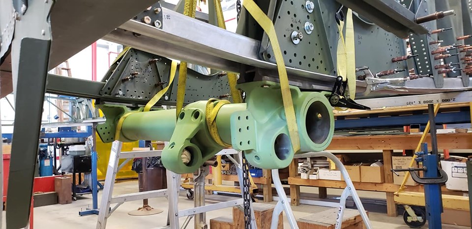
The beginnings of an engine oil tank.

It's shaping up nicely.

In situ.

With straps shown for appearance's sake: not the final positioning.

Compare to the real thing.

Wiring details. I haven't a clue.

A plan begins to emerge out of the chaos.

Holy crow!

And this! The first time I have ever seen a cut clear through the nacelle to make room for supercharger piping "in the round."

I just drop the mike on this one.

It's exquisite, even from the exterior. I just love the engineering and thought put into this impossible-to-model space.
H.G. has accomplished a lot in the past few days, and rather than offer extended commentary I'll let his work speak for itself (mostly).
Let's start with some extra detail on the superchargers.
He's getting there with these "brass ring" additions.
Here is some landing gear detail from the Verlinden set. Note the wiring.
Moving right along.
Brutal "rip out" work getting the wheel wells ready for what's to come.
Measuring the top of #2 engine wheel well.
Can you guess what this is? Hint: Not wing filler.
The beginnings of an engine oil tank.
It's shaping up nicely.
In situ.
With straps shown for appearance's sake: not the final positioning.
Compare to the real thing.
Wiring details. I haven't a clue.
A plan begins to emerge out of the chaos.
Holy crow!
And this! The first time I have ever seen a cut clear through the nacelle to make room for supercharger piping "in the round."
I just drop the mike on this one.
It's exquisite, even from the exterior. I just love the engineering and thought put into this impossible-to-model space.

AbramJ
Joined: February 07, 2015
KitMaker: 45 posts
AeroScale: 44 posts
Posted: Monday, August 19, 2019 - 02:46 PM UTC
Its been a while since I posted here and I must say, Brian, when I saw you were passing the project on I was a little disappointed and worried it wouldn't hold up to the level of detail you've put into it so far. HG has definitely put those worries to bed, amazing work! Keep the updates coming please!
Joel_W
Joined: December 04, 2010
KitMaker: 11,666 posts
AeroScale: 7,410 posts
Posted: Tuesday, August 20, 2019 - 01:08 AM UTC
HG's work is just a constant example proving that he's a certified Alien. There's no other plausible explanation.
I've seen super detailed aircraft many times in the past, but nothing comes close to this.
Joel
I've seen super detailed aircraft many times in the past, but nothing comes close to this.
Joel
Redhand
#522
Joined: January 20, 2013
KitMaker: 1,460 posts
AeroScale: 1,443 posts
Posted: Tuesday, August 20, 2019 - 09:03 AM UTC
Quoted Text
Abram:
Its been a while since I posted here and I must say, Brian, when I saw you were passing the project on I was a little disappointed and worried it wouldn't hold up to the level of detail you've put into it so far. HG has definitely put those worries to bed, amazing work! Keep the updates coming please!
I will. Let me just say the biggest compliment HG has paid me in doing this work is that he wants to "do justice" to my efforts on the interior. Coming from someone with his talent, that's rare praise indeed.
I couldn't be happier with how this build is shaping up. He's doing things I could never achieve, even if I had the time.
Redhand
#522
Joined: January 20, 2013
KitMaker: 1,460 posts
AeroScale: 1,443 posts
Posted: Friday, August 23, 2019 - 05:07 PM UTC
WHEEL WELL WONDERS
We should start with "the real thing" space HG is working on now.

Remember this part of it:

Let's go to some rough images of the supercharger piping fitting into the oblong opening cut into the side of the nacelle.
First, from the interior:

And from the opposite side:

And here's a step-back look as we see additions where the main landing gear strut will fit.

The green shows me how H.G. integrated the kit part into the overall, custom design.
Here are some exterior shots of the supercharger piping test-fit into the side nacelle opening:


When I mentioned to H.G. that I didn't envy him the finishing work on the rough edges of the opening, he replied with this.

"A good workman praises his tools," I guess.
Here's an interior shot that also shows some rough piping.

However, I have no concerns it will stay that way.

I am told this aluminum foil is not the stuff you buy in the supermarket.
Here's more interior piping extending to the back bulkhead of the wheel bay, and new details:

And what is that at the open end of the pipe?

Hell, it looks like a filter! H.G. is this one of these, "no one will see it but I know it's there" things? It's clear you cut out some black circles and we're not just looking at a hole.

As to that resin/plastic stuff up at the top, I really am saving the best for last. The question is, "How does that relate to these exquisite three-part landing gear legs that pull the main landing gear strut up into the wheel well. SCRATCH BUILT.

[Note: I haven't seen work like this since Chuck W's epic build of the Icaerodesign 1/48 IAR 81C- kit. I wonder what happened to him!? I liked his cheesecake drawings too.]
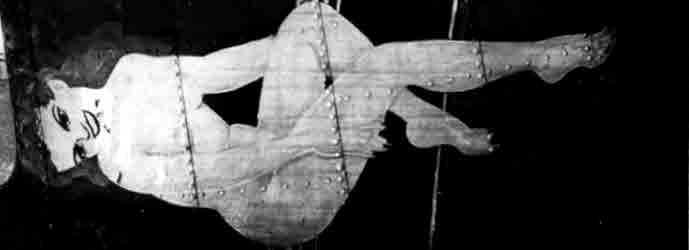
For the answer, remember the photo I said to look at up at the top of this post. To make the subject clearer, what is the black thing at the top of this other B-17 wheel well photo?

It sure looks like anelectro-hydraulic motor/pump electric motor [H/T Karl] that retracts and extends the landing gear strut and wheel into and out of the nacelle.
And here is H.G.'s preliminary scratch-build of this humble but essential component.

Again, I have no words.
We should start with "the real thing" space HG is working on now.
Remember this part of it:
Let's go to some rough images of the supercharger piping fitting into the oblong opening cut into the side of the nacelle.
First, from the interior:
And from the opposite side:
And here's a step-back look as we see additions where the main landing gear strut will fit.
The green shows me how H.G. integrated the kit part into the overall, custom design.
Here are some exterior shots of the supercharger piping test-fit into the side nacelle opening:
When I mentioned to H.G. that I didn't envy him the finishing work on the rough edges of the opening, he replied with this.
"A good workman praises his tools," I guess.
Here's an interior shot that also shows some rough piping.
However, I have no concerns it will stay that way.
I am told this aluminum foil is not the stuff you buy in the supermarket.
Here's more interior piping extending to the back bulkhead of the wheel bay, and new details:
And what is that at the open end of the pipe?
Hell, it looks like a filter! H.G. is this one of these, "no one will see it but I know it's there" things? It's clear you cut out some black circles and we're not just looking at a hole.
As to that resin/plastic stuff up at the top, I really am saving the best for last. The question is, "How does that relate to these exquisite three-part landing gear legs that pull the main landing gear strut up into the wheel well. SCRATCH BUILT.
[Note: I haven't seen work like this since Chuck W's epic build of the Icaerodesign 1/48 IAR 81C- kit. I wonder what happened to him!? I liked his cheesecake drawings too.]
For the answer, remember the photo I said to look at up at the top of this post. To make the subject clearer, what is the black thing at the top of this other B-17 wheel well photo?
It sure looks like an
And here is H.G.'s preliminary scratch-build of this humble but essential component.
Again, I have no words.
Joel_W
Joined: December 04, 2010
KitMaker: 11,666 posts
AeroScale: 7,410 posts
Posted: Saturday, August 24, 2019 - 02:06 AM UTC
Brian,
Once again, I'm actually just speechless. This isn't modeling as we know it, but something of a much higher order.
Joel
Once again, I'm actually just speechless. This isn't modeling as we know it, but something of a much higher order.
Joel
KPHB17FE
Joined: January 12, 2015
KitMaker: 292 posts
AeroScale: 292 posts
Posted: Saturday, August 24, 2019 - 02:23 AM UTC
As usual, fantastic work. Just a word about terminology: The gear is driven by an electric motor, period. No hydraulics are involved  ! Useless fact for all of you: Each gear (both mains and tail wheel) had their own electric motor. This same motor was used to drive the bomb bay doors. Just in case you ever need a spare gear motor in your B-17...
! Useless fact for all of you: Each gear (both mains and tail wheel) had their own electric motor. This same motor was used to drive the bomb bay doors. Just in case you ever need a spare gear motor in your B-17...Redhand
#522
Joined: January 20, 2013
KitMaker: 1,460 posts
AeroScale: 1,443 posts
Posted: Saturday, August 24, 2019 - 09:04 AM UTC
Quoted Text
As usual, fantastic work. Just a word about terminology: The gear is driven by an electric motor, period.
Thanks for the correction, Karl. I guessed wrong on this one. It does make more sense that there would be a direct electric drive to the actuator. I corrected the text with a hat tip to you. I assume the motor drives a ballscrew?
 |

WEB HOSTING BY


Copyright ©2021 AeroScale and Kitmaker Network, a subsidiary of Silver Star Enterprises
All Rights Reserved. Please read our Conditions of Use and Privacy Policy.
All Rights Reserved. Please read our Conditions of Use and Privacy Policy.