The Fokker D.VII became Germanys main production fighter in 1918. Usually matched with the Mercedes D.IIIaü 180hp engine. It was the variant with the BMW IIIa 185hp motor that pilots prized ultimately. With few idiosyncracies it was not temperamental and a novice with a little nerve could do well. Contemporary construction using welded metal tubing for the fuselage and wooden wing structures was typical. The secret appeared to be in the cantilever boxed wing spars and the simple design that eliminated the need for multiple exposed rigging wires. For several reasons the Fokker D.VII is a must have item in the serious collector/modelers stable. The lack of rigging is a big plus, the various decal sheets of cookie-cutter lozenge, unit and pilot markings that are available in most scales. References on the subject are also at an all time high.
Kit Contents
#32031 1/32 Fokker D.VIIF US$79.00
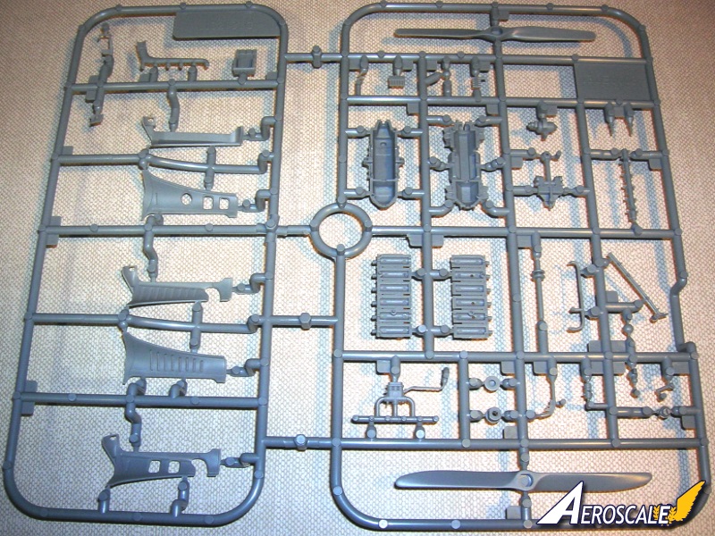
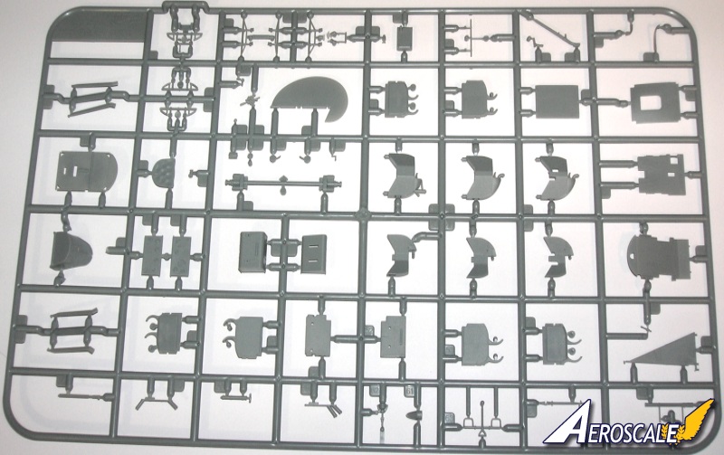
1. 198 high quality injection moulded plastic parts.
2. Includes 36 exclusive parts to build late & early production aircraft with the BMW motor made by the Fokker factory in Schwerin.
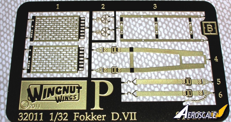
3. 8 photo-etched metal detail parts.
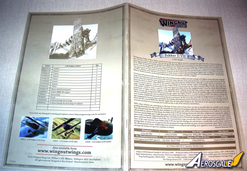
4. 32 page fully illustrated instruction manual.
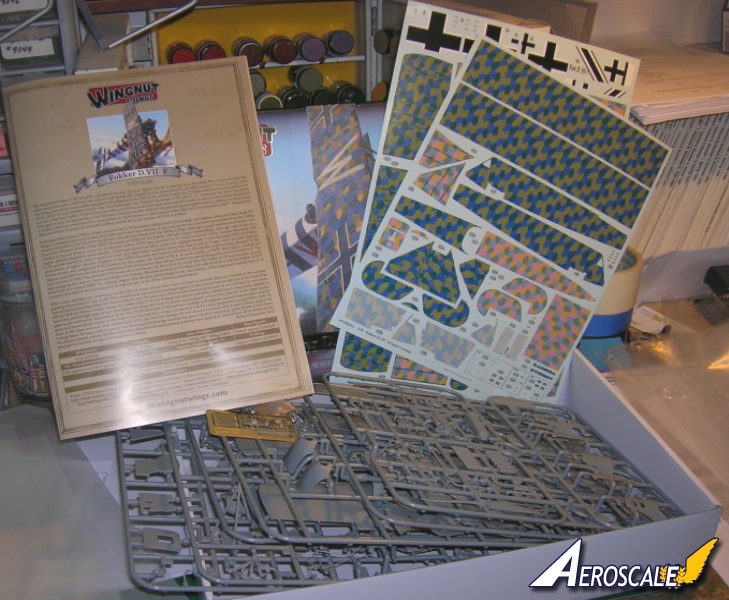
5. 3 high quality Cartograf decal sheets with markings for 5 aircraft.
This is the typical quality reference that we have come to expect from WNW kits. The graphics an high quality images give us a monograph that will become a permanent fixture in our reference libraries. The step by step guide is easy to follow in most cases. The captions for the build steps and reference photos give you a good understanding of the subject matter. But one must realize that some subjects are a bit of a guess. Colours are noted for every item in the build. Tamiya, Humbrol and Misterkit model paints are solid references.
WNW has done four separate Fokker D.VII kit issues in a four month period. Two each for Fokker (Schwerin) and one each (so far) Albatros (Johannistahl) and OAW(Schneidemuhl) machines. By the way there were ALB. & OAW machines that had BMW IIIa motor. From what we know they carried the "F" designation but only on the factory nameplates, not on the fuselage side panels.
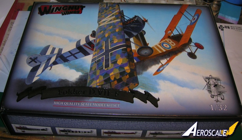
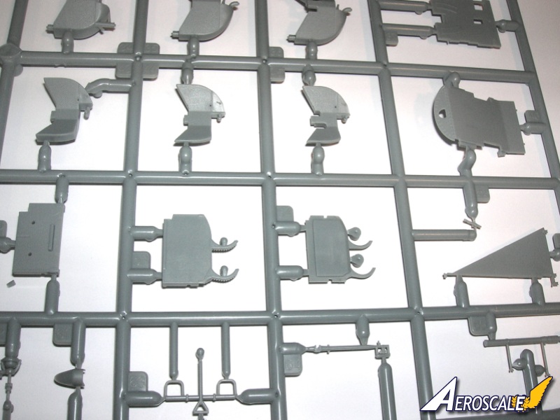
Kit #32031 represents the Fokker factory -built version with the 200hp BMW IIIa motor and arrives in the WNW typically colourful top opening box, with the sprues, instructions, decals and accessories all individually bagged for protection. The moulding in the review kit is crisp, sharp, clean details and no flash. A close inspection with an optivisor showed a couple of minor sink marks on the underside of the fuselage and on the firewall and will prove easy to clean up. Ejector pin marks are well placed out of sight when the finished cockpit is viewed.
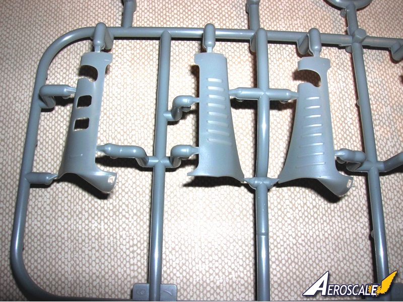
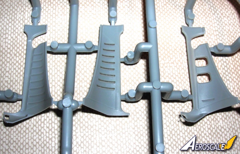
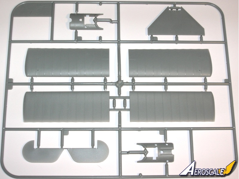
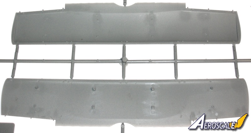
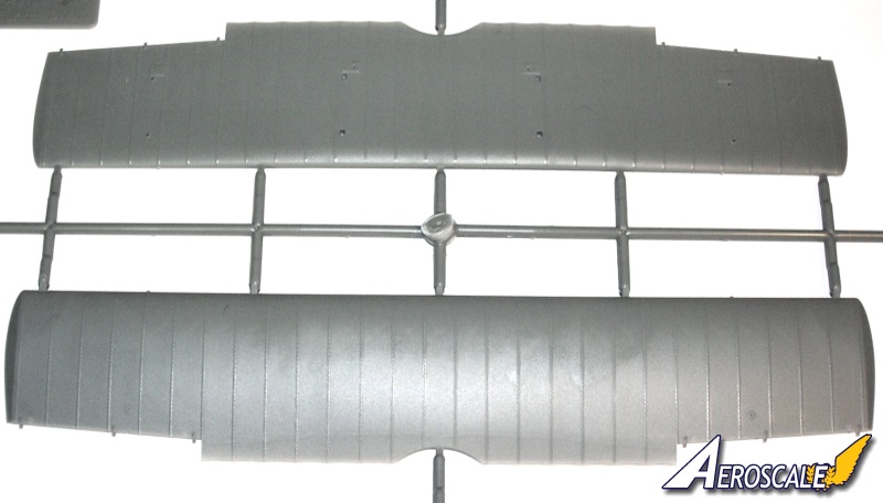
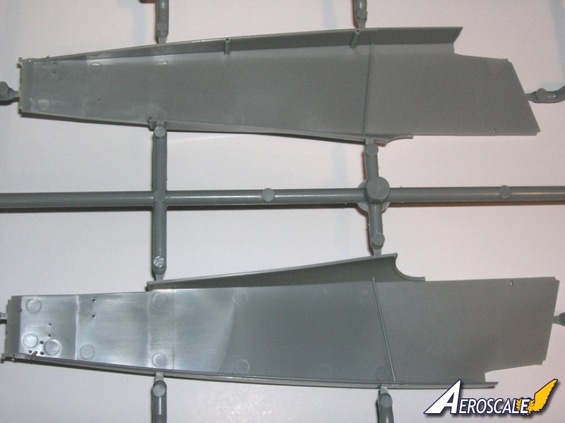
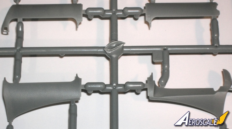
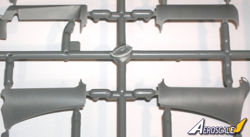
The surfaces of the model have finely engraved panel lines, raised detailed fasteners and options for adding servicing ports. The louvres in the side cowling panels are depicted with open slots. The depiction of the fabric covering, in-scale rib tapes on the wings and horizontal stabilizer. A very faintly "ballooned" effect on the undersides of the wings to depict the weight of the material on a machine at rest. DML wrongly caught a tremendous amount of flak when they did this to their 1:48 Fokker Dr.I in 1992.
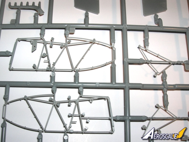
Aeroscale Managing editor Merlin has already noted (and it is worth repeating) a caution that . . .many of the smaller parts are quite delicate, being moulded as close true-to-scale as possible yet their sprue-attachments are substantial to acheive the crisp level of detail. . . I recommend using a cutting wheel in a variable speed motor tool at low revs to remove any parts to prevent damaging them.
The build
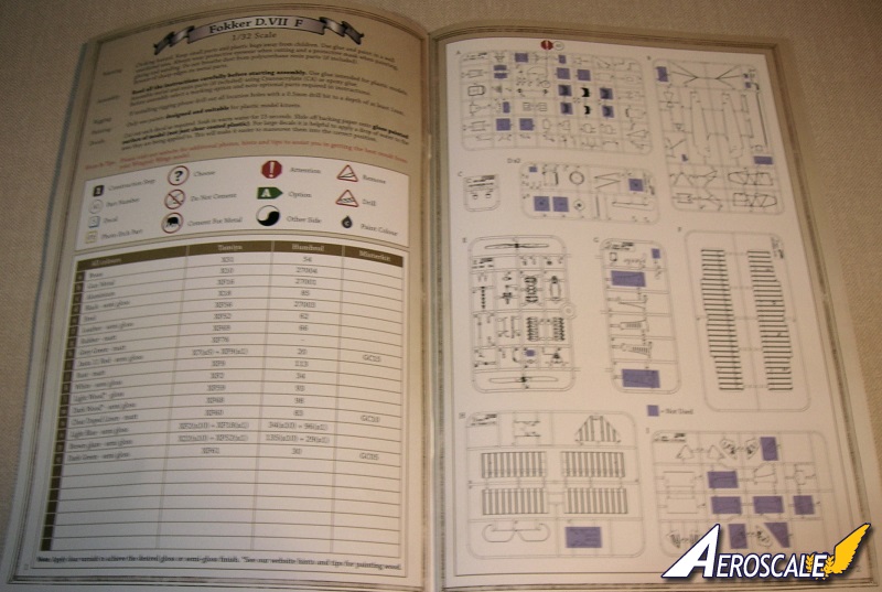
Page 1 First we start with the typical WNW general text & colour matches for paint. Note that there are several good decal sheets available now that replicate the contrasting wood grain.
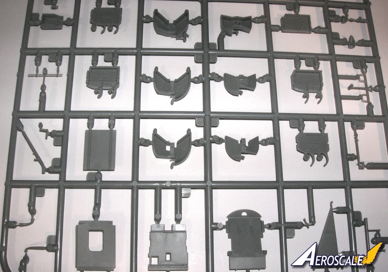
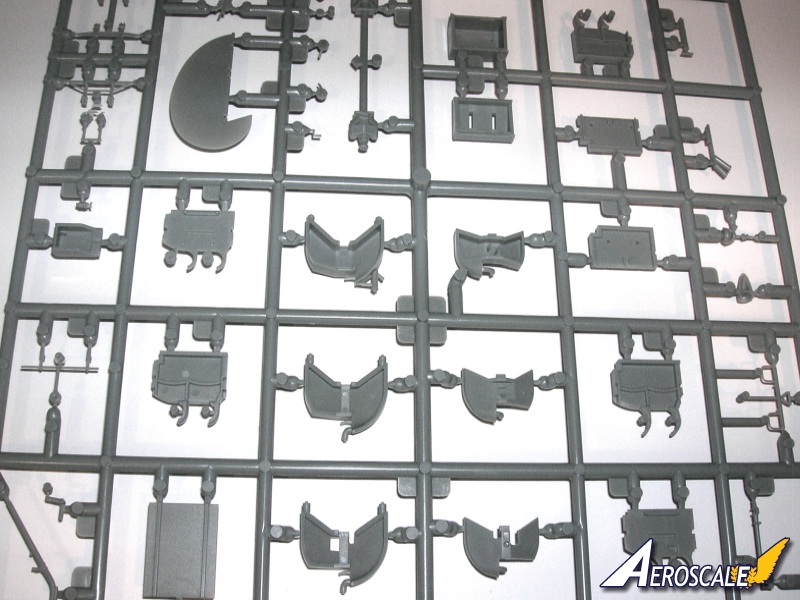
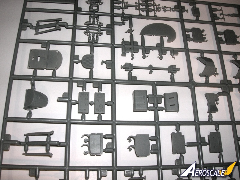
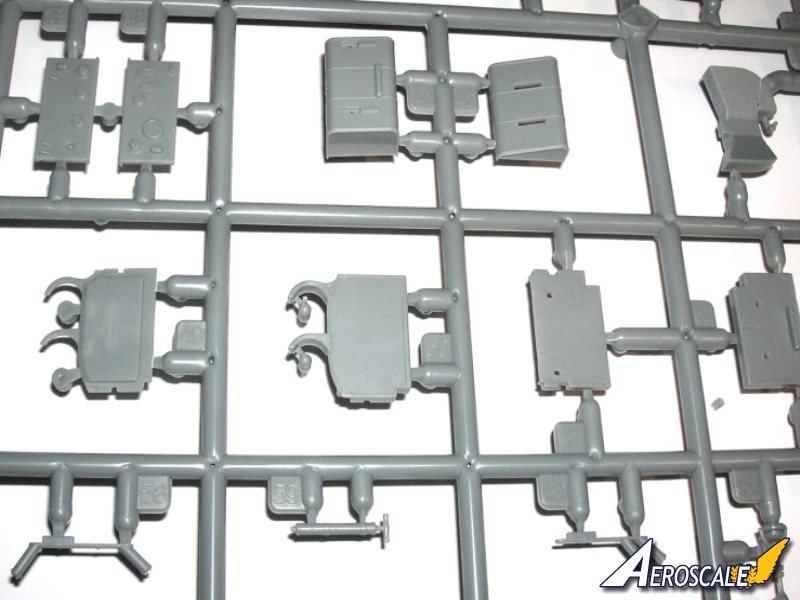
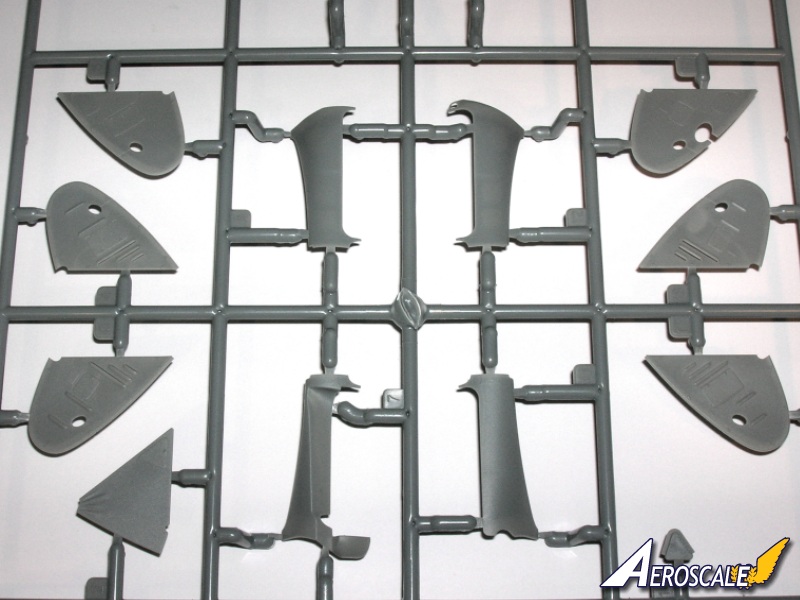
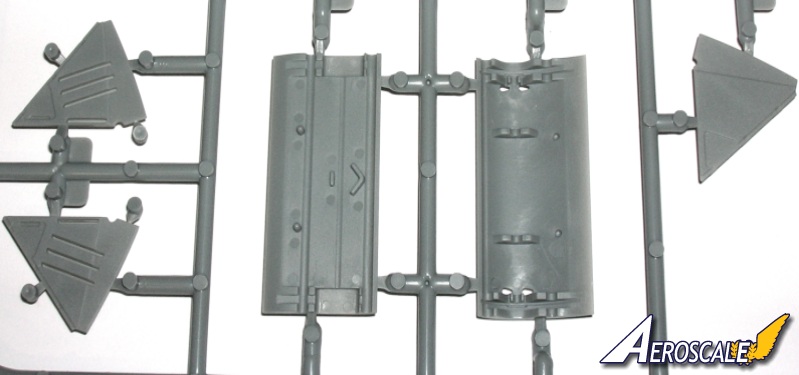
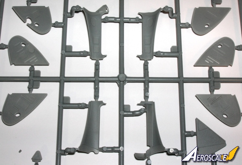
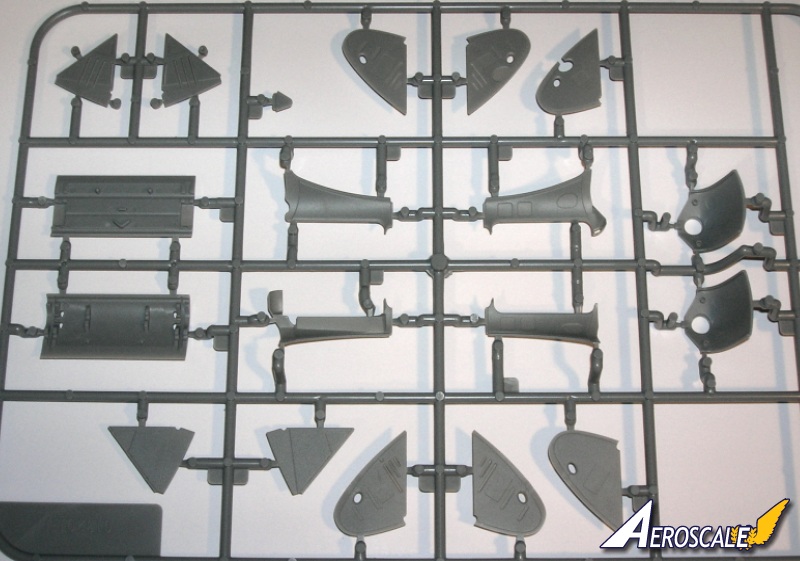
Page 2 We find the parts maps.
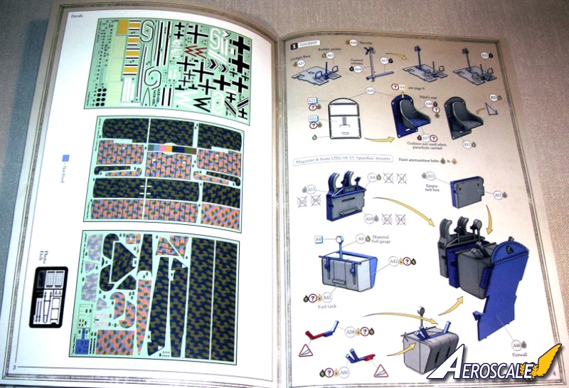
Page 3 shows the maps for the six decal sheets and the photoetch fret.
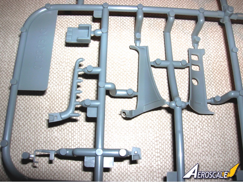
Step 1. The Cockpit.
The flooring (PP A 37) and rudder bar ( PP A 63) lateral pivot rod (PP A 57), control column (PP A 64) auxilary throttles (PP A 18) and the aileron control vee horns (PP A 11) come together. The rear cockpit screen (PP A 26) can be painted then decaled. Note the lozenge decals would be used only if the whole fuselage was to be covered in lozenge. The pilot seat (PP A 38) is attached next with the supports (PP B 21 & 22) added next. Whether the seat was recovered at the front or not from the factory the seat back had (about 210) eyelets for a fabric covering to be sewn / laced in place. They were either plain or lozenge. As noted the pilot's seat cushion (PP A 27 ) wasn't used if a parachute pack was employed.
The ammunition box (PP A 22 & 23 ) empty belt box (PP A 51 & 52 ), front gun mounts (PP A 4 ) Maximal fuel gauge (PP A 8), fuel tank (PP A 41 & 42), fuel tanks spouts (PP A 58 & 60) and firewall (PP A 46) come together next. The late Dan San Abbott mentioned that in his studies, firewalls were not installed until about the Fok. D.VII 4300/18.
For those of you that are less familar with the story, The hot summer months of 1918 manifested a problem with early Fokker D.VII types. Heat build up in the engine compartment and the lack of venting led to the premature cook off of the ammunition stores - inflight. This concerned especially the phosporous capped tracer rounds. The answer was better air induction to, and venting from the engine compartment.
The first unit to receive the new Fokker D.VII in late April/early May, 1918, was Jasta 10 of the elite Jagdgeschwader I. Their machines were marked with yellow engine cowlings. Ltn. Friedrich Friedrichs came to Jasta 10 on 11 January, 1918 from FAA 264. Here, he achieved his first aerial victory in March, increasing his combat score to 21, including 11 balloons. The destruction of observation balloons would become his specialty. On 15 July, when the ammunition storage exploded in his Fokker. Friedrichs jumped free from the aircraft, but his parachute snagged the tail unit. The parachute was torn off the harness. Ltn. Friedrichs was killed over Arcy at 20.45 hours in Fokker D.VII 309/18. The reason for the ammunition cooking off was attributed to the very hot summer weather and the lack of cooling vents / louvres. The addition of a firewall was an attempt to keep the engine heat away from the ammunition storage box. The guns were also raised. This difference is reflected in (PP A 2, 3)the forward gun supports.
Step 2. Cockpit continued.
Reflects alterations that can be done for the side frames (PP B 10 & 11) with added equipment and the flooring assembly from step 1.
Step 3 Cockpit continued.
This step covers the instrument panel (PP A 39) and its equipment. High quality Cartograf decals for the instrument faces have fine details. The rear gun mounts (PP A 1) are noted and should reflect the same heights as seen in step 1. The final height of the guns was usually a determination that designated the engine as the BMW IIIa motor. It was a taller over all profile of 11/16 of an inch.
Optinal altimeter (PP A 32 or 33) locations are discussed. In many cases smaller altimeters were worn on pilots wrists like a modern wrist watch. Though the faces were only slightly larger. Please note that the safety harness straps were in tended only to keep the pilot in the cockpit incase of erratic combat maneuvers. These narrow belts were made of a canvas.
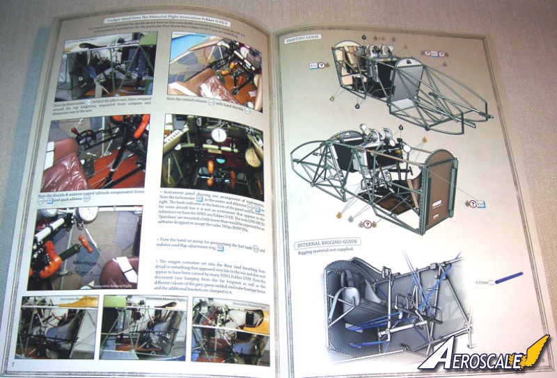
Page 7 Is a very useful set of colour reference images of The Memorial Flight Association's BMW engined replica Fokker D.VIIF aircraft cockpit. Please note that WNW do caution against relying on the images too much as some details do not match original production machines.
Note! The inside of fuselage halves (PP B 19 & 13) of profile D (and maybe E ) are lined with a panel of reversed lozenge decal to represent the pattern showing through the rear of the fabric on the original. These appear lighter as the dye did not penetrate the fabric in a distinct manner. See also step 6.
Page 8 This is the general painting and rigging guide for all components assembled to this point.
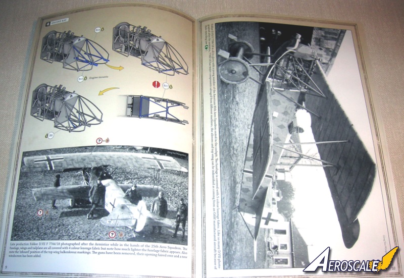
Step 4 Detailing the engine compartment.
Here we add the engine bearers (PP B 14 & 15) and their secondary supports (PP B 17). Commendably thin and an ingeniously designed as a single unit.
Page 10 This is a full page study of the pilots left front quarter view of Fokker D.VIIF 7788/18 as assigned to the 25th Aero. Not the 85th as the caption indicate.
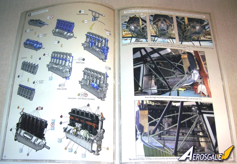
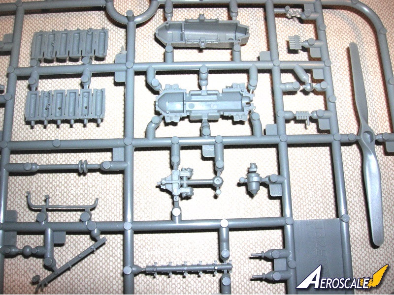
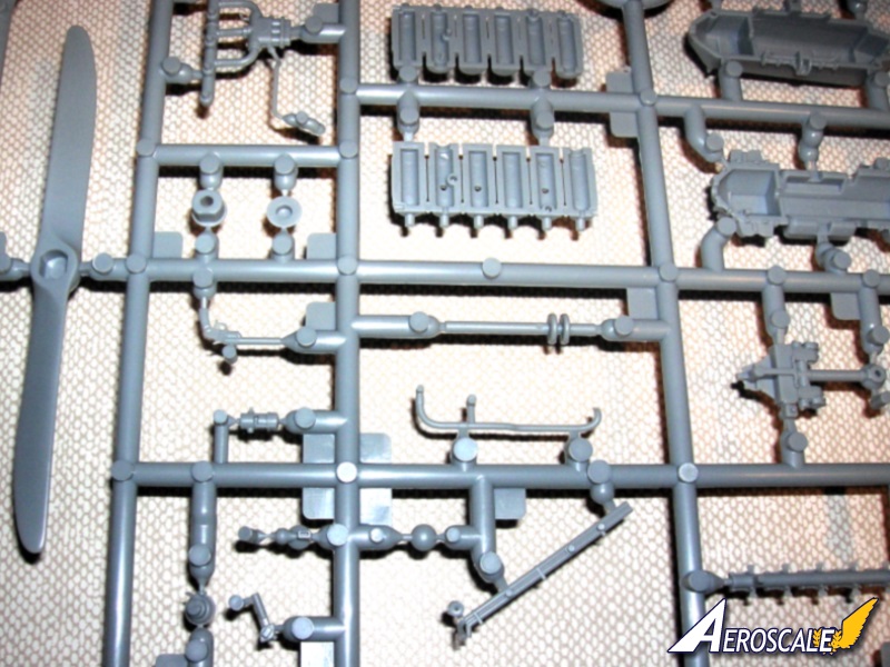
Step 5 Engine.
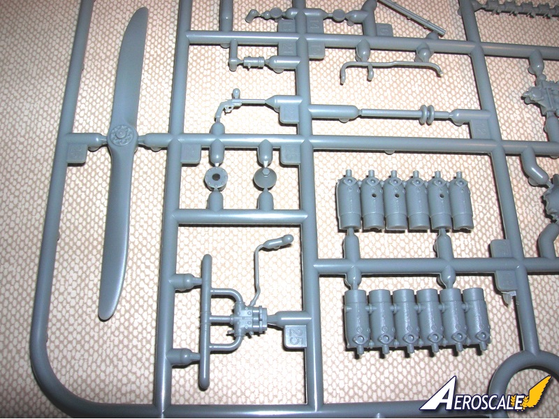
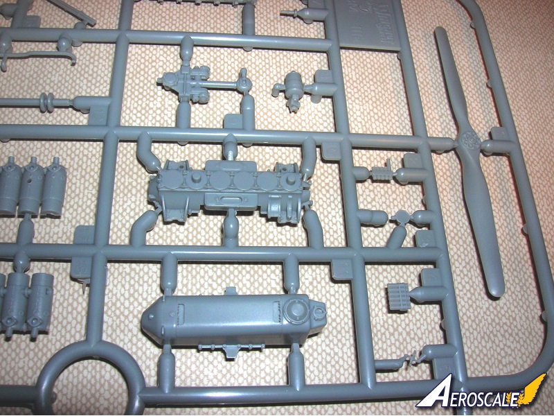
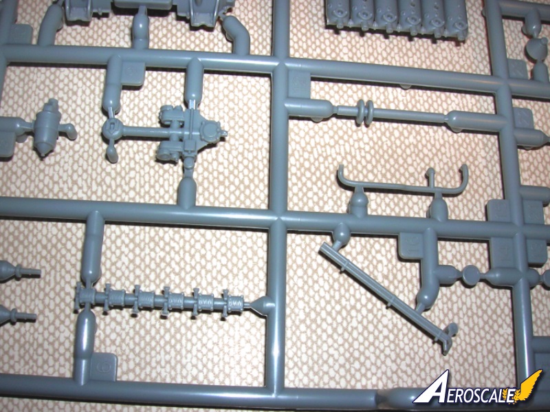
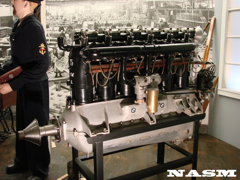
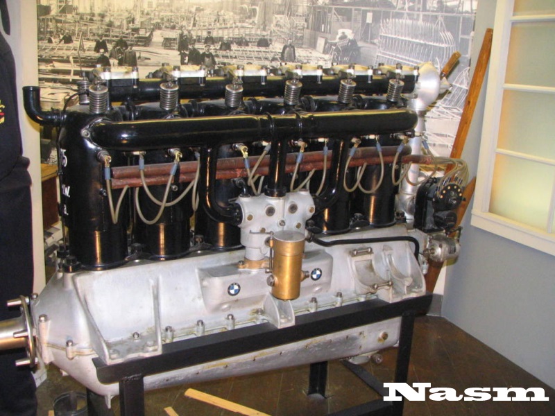
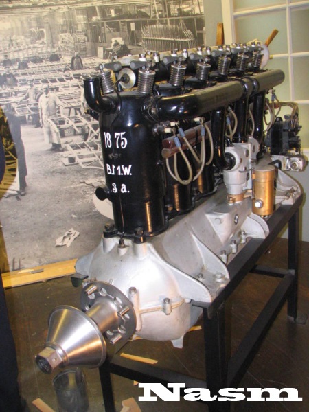
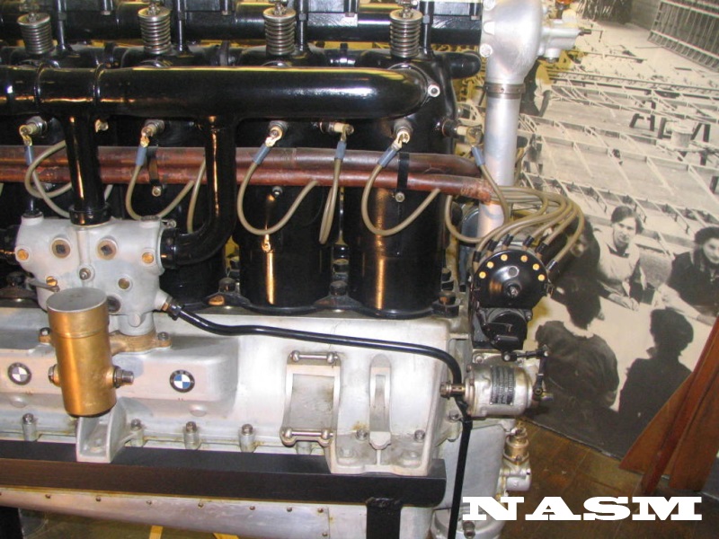
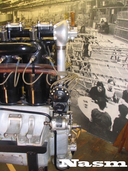
Wingnut Wings have used their typical E sprue for the BMW IIIa 200hp mouldings. I recommend solder and brass wire / rod for the plumbing & wires. (rated between 200hp - 220hp). On their BMW IIIa 200hp six cylinder inline engine WNW uses ( PP E 6-12, 16-21, 25& 30). The aircraft engine cylinders are covered by water jackets these are the color of black/blued gun metal. The kit includes the oil filler tubes / vent caps (PP E 7 X 2), water cycling pipe (E 30) and the sparkplug wire conduit tubes (PP E 16 ). Captured examples of this motor have labeled it a 230hp type due to the differences between German and British ratings for horsepower.
What you do get in the kit is the water line tubes (sending and receiving) from the water pump to the radiator. You need the oil sending tubes for the resevoir tank and upper & lower casing. This was located on the pilots right side of the engine midway and is to be flanked by two flanges. But again you can add these from solder. Note the carburetor set up (E 21) and its orientation. On the BMW IIIa type motors the decompression lever (PP E 19) was at the top of the tower (PP E 9) and employed during engine maintenance & repair. The handle was wood and could be unscrewed. The crank cases that had the generator shelf were normally for wireless equipped machines or heating unit. Only one Fokker D.VII is known to have had a wireless, yet the shelf as a standard option and appears to have been added regardless of airframe application.
Page 12.
BMW IIIa 185 - 200hp serials begins with the 12xx series designation. Here you see the Memorial Flight replica with a BMW IIIa only partially hooked up for operation. Add fine wire painted black or white to make spark plug wires.
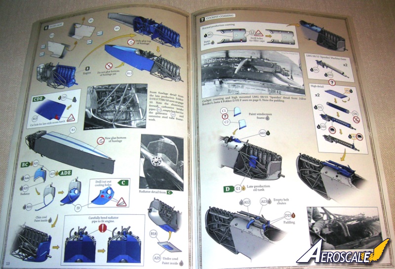
Step 6. Fuselage.
Note! The inside of fuselage halves (PP B 9 & 13) panel of reversed lozenge decal to represent the pattern showing through the rear of the fabric on the original. These appear lighter as the dye did not penetrate the fabric in a distinct manner. Next we add the sub assemblies to the fuselage halves (PP B 9 & 13) and unite them. WNW recommends sealing the fuselage spine joint first. Aeroscale Managing Editor advises it does no harm to reinforce this seam with a strip of stock sheet plastic inside the fuselage to overlap the edges. I strongly agree.
The radiator (PP A 35), water fillet tubes (PP A 19 or 31), inset faces (PP A 44) and chin cowl (PP I 9) assemble at this time. There was a need to create a larger surface for the summer cooling problems, so the early radiator with the narrower center section (PP A 35) gave way to the one with the wide center section (PP A 34) and offset fillet tube (PP A 31).
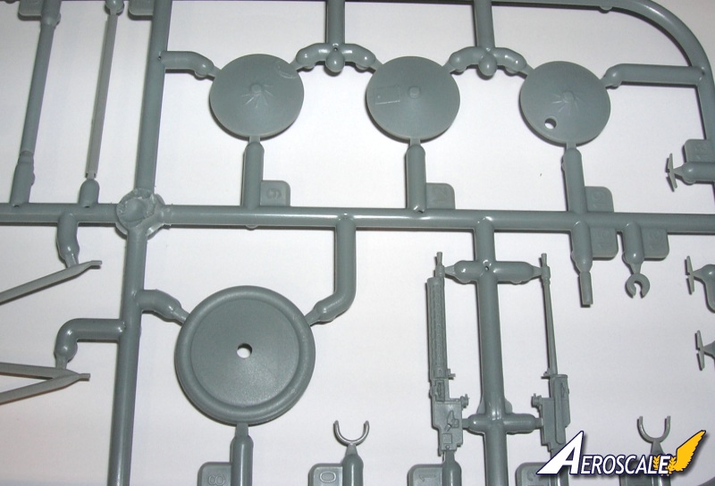
Step 7. Cockpit forward deck & guns.
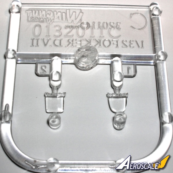
One option is given for the top decking (PP H 1 ) ahead of the cockpit, The pair of LMG 08/15 "Spandau Maxims"(PP D 11 X2, D 1x 2) can be attached to the"high" mounts and are provided in all plastic and you can further detail them with photo etched fretted cooling jackets and sights. The windscreens (PP C 1 or 2 ) should be added last in my opinion. Locations for the separate oil tank (PP G 1), empty belt tubes (PP A 12 & 13), fuel gauge fairing (PP A 61) for the fuel gauge (from step 1) and the pads for the gun butts (PP D 15 X 2) are discussed.
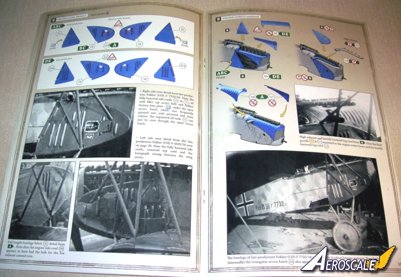
Step 8 Engine cowlings.
Variations of the engine cowling panels are provided. Two are versions for the early (PP I 3, 4 or 18) (I 1& 2) and one for the later (PP I 3 & 4) (PP I 14 & 15) all are high mounted exhausts. Choose the ones appropriate for the profile you are building.
Step 9 Engine cowlings continued.
WNW has detailed their exhausts with weld-seams. The choice in exhausts is of course low or high mounted. Check your profile for the build. One note if you have missed this you will find the radiator half shell is actually moulded to the pilots right upper engine cowling (PP G 6 or 8 ). Often this small plate was retained on the radiator shell when the upper engine cowlings were removed for summer / fall operations.
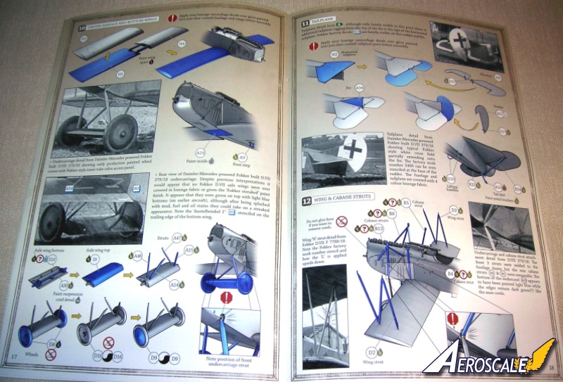
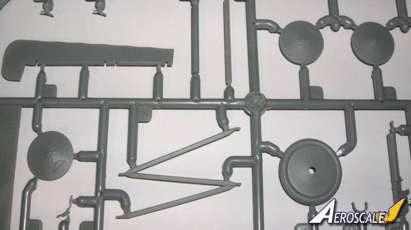
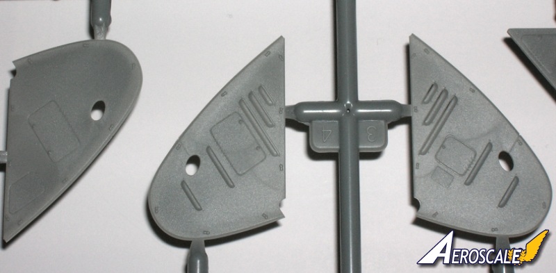
Step 10 Under carriage & bottom wings.
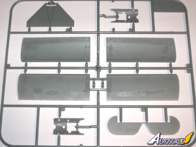
The lower wings (PP H 3, 4 & 5) appears adequate for the application Though I wish the spars had run a bit deeper into the lower wing shells. Not just for the added stability but if you wanted to do a bit of battle damage it would make it easier. This is not a flaw mind you. Just my opinion.
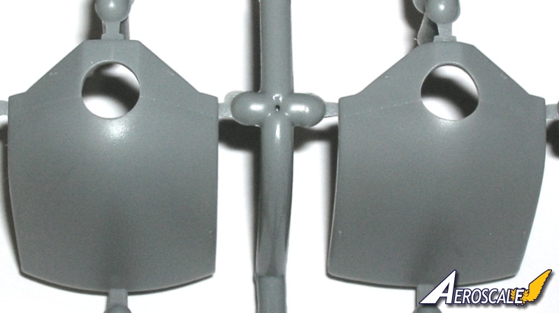
The undercarriage assembly has a very stout axle (PP A 30). The Fokker Schwerin wing axle (PP I 9 & 10) was fixed and built around the axle. Others (Johannistahl & Schneidemuhl ) would design the wing axle as removeable. The wheels (PP D 8 X 2) are detailed with raised letters on the tires and air valves visible behind the separate outer covers (PP D 9 X 2).
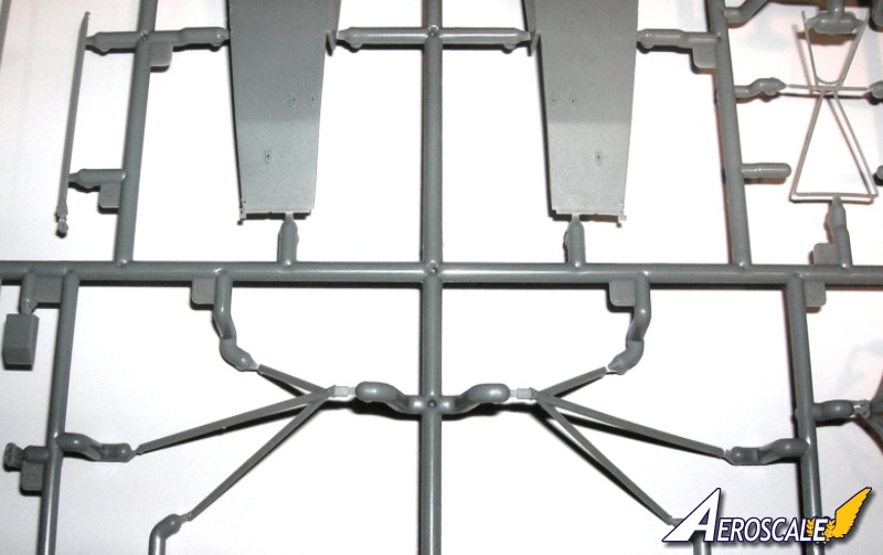
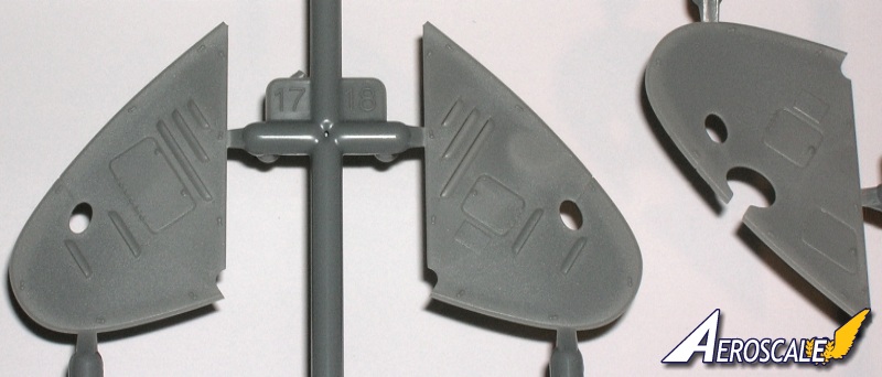
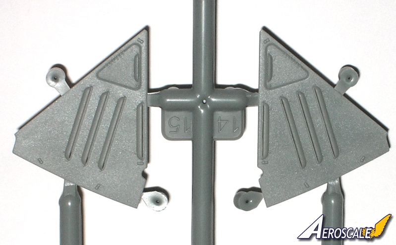
Step 11 Tailplane.
The horizontal stabilizer (PP H 2), elevator (PP H 6, D 17 X 2), fin (PP A 56) and rudder (PP A 21, D 17) braces (PP B 23 & 24) Tail skid (PP A 10) and lifting handles (PP D 10 X 2) are all added here.
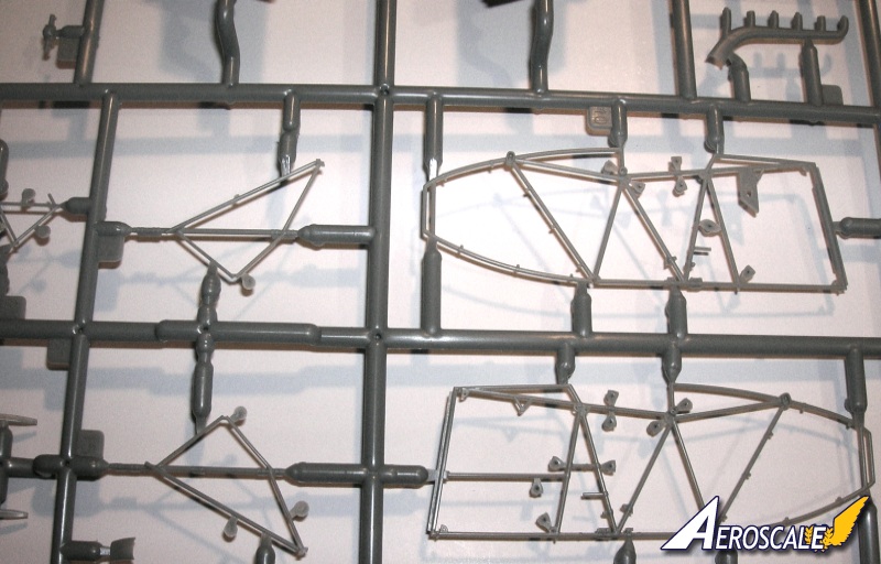
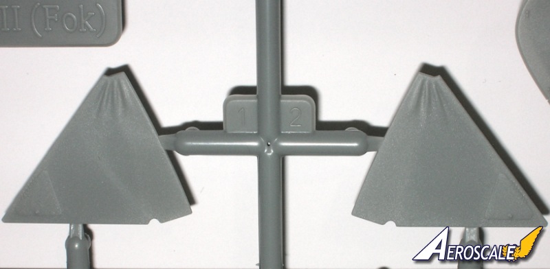
Step 12 Wings and Cabane struts.
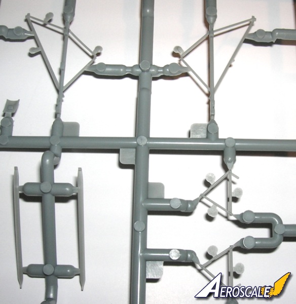
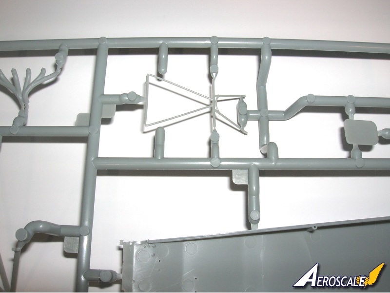
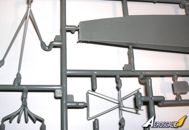
Note the tripod forward cabane struts (PP B 8 & 12) were welded together at their high apex and to help you with that WNW has them as one moulded unit for each side. The N shaped wing struts (PP D 2 X 2) are commendably thin & in-scale.
Page 19
As an addition the flash guard troughs (PP D 7 X 2)(PE 3) in my opinion were seen on machines after the problems with the engine compartment over heating issue in the summer months of 1918. This was another measure that was meant to keep tracer rounds from igniting any fuel or oil fumes. Usually only the small muzzle flash plates were seen on early Fokker built airframes.
Step 13 Top wing & final assembly.
Finely moulded Heine (PP E 1) and Axial (PP E 24) propellers are specified for use in the colour schemes provided . Note the instructions say that they were often replaced with different types in service, so some latitude if you so chose. If you are modeling the aircraft from a specific reference it is good to follow that.
WNW has made attaching the upper wing an easy affair. The main "N" strut slots may have to be opened but dry fit before committing glue. As on the original aircraft, it is the cabane struts that do the load-carrying, with pretty substantial lugs supporting the wing. The forward tripod struts (PP B 8 & 12) are moulded as one unit and should make it easy.
Page 20 Rigging diagram.
The attraction for most modelers is the lack of rigging on the Fokker D.VII. A pair of cables run from the fin to the horizontal tail, another pair brace the undercarriage, then there are control cables to add for the ailerons, elevator and rudders. There are two stabilizing cables for the vertical fin. That's it. The instructions include a rigging diagram showing the aircraft from two angles.
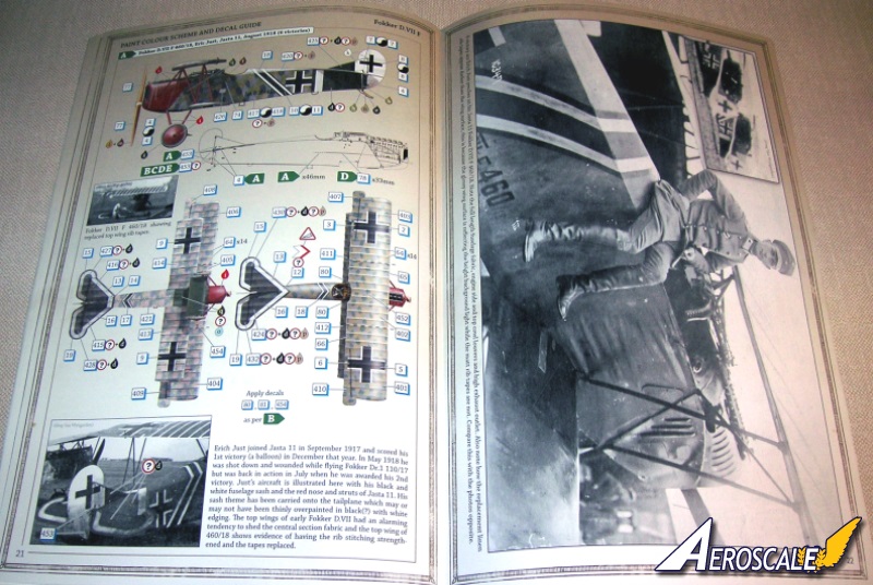
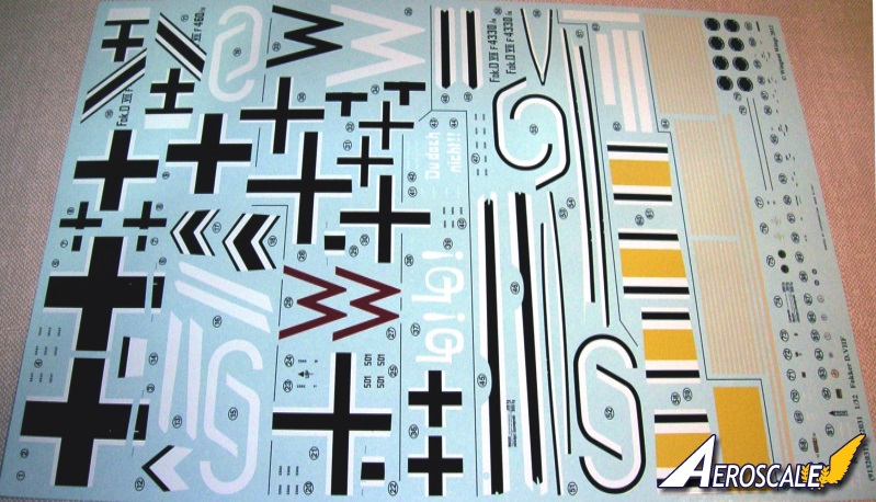
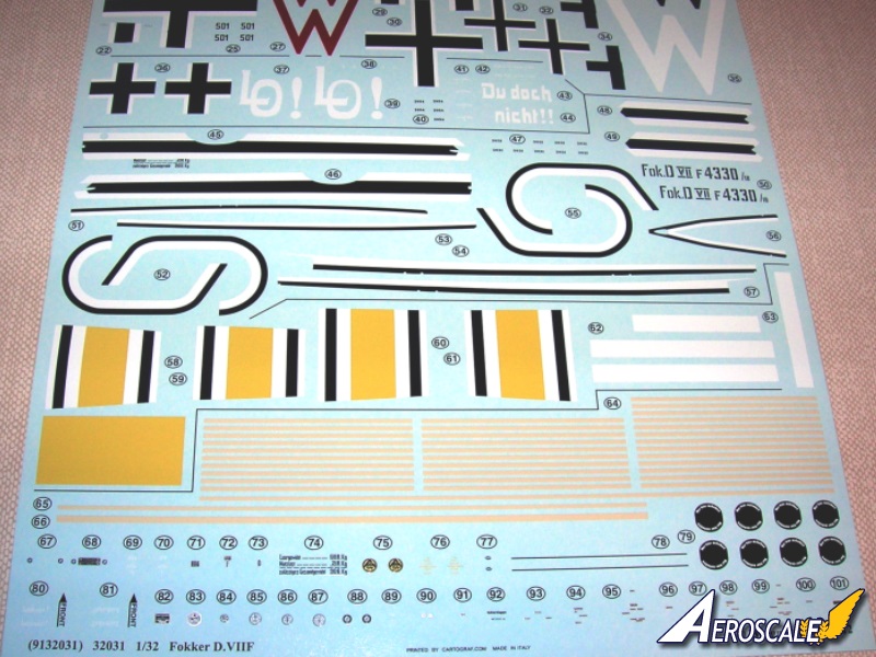
Decals
Three sheets! Cartograf, registration is as close to "painted on" as you will see in waterslide decals. It is impressive is the way overlapping markings are grouped as single decals. This is something we have seen on other Carograf sheets and seems to be one of their hallmarks
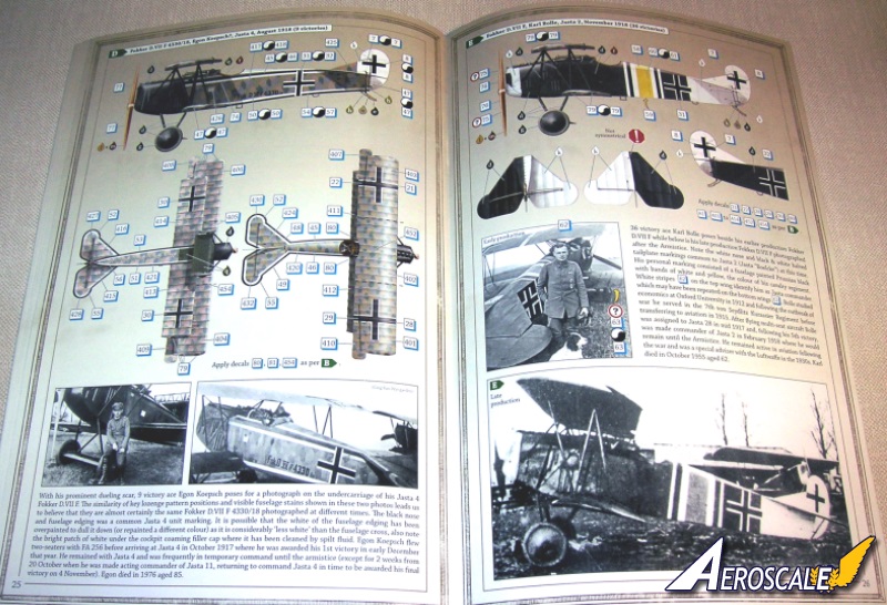
A. Fokker D.VIIF 460/18 Ltn Eric Just, Jasta 11, August 1918. Lt. Just was wounded on 1 March & 3 May and returned to the unit both times to serve until EOW. Note also when a soldier was awarded a medal it was a popular theme to have the ribbon of the award added to the aircraft's fuselage near the iron cross. Symbolic of the award even when the cross types changed.
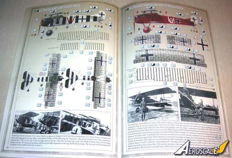
B. Fokker D.VIIF 501/18, W, Jasta 26, November 1918. This machine may have been assigned to Ltn.d.R. Jakob Wolff.
C. Fokker D.VIIF 4253/18 Oblt Ernst Udet, Jasta 4 KO, (July ?)-September 1918. Highly recognizable fellow also served as JG I acting commander while Oblt. Göring was on leave, espesially during this time period.
D. Fokker D.VIIF 4330/18 Ltn Egon Koepsch(?), Jasta 4, August 1918. He was also originally an Uhlan cavalry officer.
E. Fokker D.VIIF serial unknown Haupt. Karl Bolle, Jasta 2 KO, November 1918. After being named the Jasta 2 KO on 20 Feb. 1918. Later when he was awarded the Orden Pour le Merite and was granted the usual four weeks leave from 4 Sept. But it was cut short by 10 days as evidenced by his return on 18 Sept.
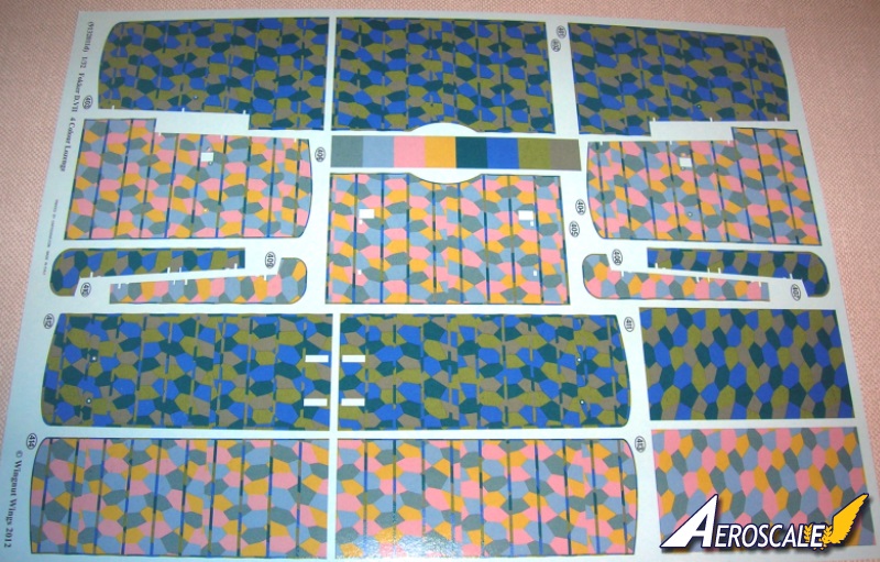
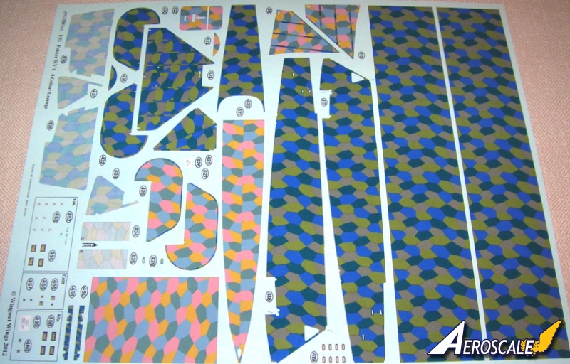
Lozenge Decals
Two of the decal sheets are devoted to lozenge camouflage decals, with both 4 colour patterns. in "cookie cutter" types to make for simpler application. A nice addition is patches of each colour for spot repairs. The colours of the lozenge camouflage decal have been dealt with in past reviews here at Aeroscale and it can be said that they are still good overall and I would include texturing even as they themselves have allowed to be done on their display models.
Production serials of the Fok. D.VII built by Schwerin Fokker Co.
Fok.D.VII 227-229/18 prototypes, V.11 and two V.18 brought up to Fok.D.VII production standards.
Fok.D.VII 230 to 526/18. Some D.VIIF (BMW IIIa) engines.
Fok.D.VII 4250 to 4449/18. Some D.VIIF (BMW IIIa) engines.
Fok.D.VII 5050 to 5149/18. Some D.VIIF machines.
Fok.D.VII 7604 to 7805/18. some D.VIIF machines.
Fok.D.VII 10347 to 10300/18. 37 made, delivered after 11/11/18.
References
Combat Colours #14 The Fokker D.VII by P. Cooksley, Airfix Magazine. Date unknown.
Details & Colours Windsock Intl. Vol.3 #3 Summer 1987.
Fliegertruppen #2 by A.Ferko, Privately Published, Salem Ohio, 1987. (photocopies may be obtained by contacting the University of Texas at Dallas through the special aviation collection.)
Flight Report Cross & Cockade Great Britain, Vol. 2 # 4.
Fokker D. VII Aces of WWI, pt. I by Franks & Van Wyngarden. Osprey pub. 2003.
Fokker D. VII Aces of WWI, pt. II by Franks & Van Wyngarden. Osprey pub. 2004.
Fokker D.VII by Egon Kreuger, Profile Pub. Ltd. 1962.
Fokker D.VII by P. Grosz, Albatros Pub. Ltd, Datafile #9. 1989, 1993, & 1994.
Fokker D.VII Anthology 1 by R.Rimell, Albatros Pub. Ltd. 1997.
Fokker D.VII Anthology 2 by R.Rimell, Albatros Pub. Ltd. 2000.
Fokker D.VII Anthology 3 by R.Rimell, Albatros Pub. Ltd. 2002.
Fokker D.VII Kit Survey by R.Rimell, Albatros Ltd. Windsock Vol 13, #4 1997.
Fokker D.VII Covering Practices by Dan-San Abbott, WWI Aero #102, Pp.22-33. 1984.
Fokker D.VII Detail Marking and Finish of Fokker-built D.VII Aircraft by Dan San Abbott, WWI Aero #107, 1985.
Fokker Fighters of WWI by A. Imrie, Osprey, Vintage Warbirds #6 Pp.41-64 1986..
Fokkers Last Deadly Scourge by M. OLeary, Air Combat, Pp. 18-26. 1975.
Forgotten Fokker by P Cooksley, Cross & Cockade GB Vol.4, #2,Pp.84-86. 1973.
That Fokkers an Albatros! By Wally Tripp, WWI Aero, #102 , Pp.14-21. 1984.
Udets Fokker D.VII Fighters by Dan-San Abbott, Windsock Vol.4, Spring 1989.
German Army Air Service in WWI by R.Rimell, Osprey, Vintage Warbirds #2, Photos 42-44, 1985
Germanys Last Knight of the Air by C. Degelow, William Kimber Pub. London, 1979.
Wings of War by R. Stark, Arms & Armour Press. 1973.
When contacting retailers or manufacturers, please remember to mention that you saw their products highlighted in review here on Aeroscale.
Highs: The usual high standard of WNW details and design. Decals are impressive, sharp and in register. Instructions well done.Lows: An overlapping internal strip of plastic stock in the rear fuselage would help support the spine joint. Minor typo in text. Weight displaced tires would be nice as well.Verdict: One of the best Fokker D.VII kits to date. Well worth the price.
Our Thanks to Wingnut Wings! This item was provided by them for the purpose of having it reviewed on this KitMaker Network site. If you would like your kit, book, or product reviewed, please contact us.
About Stephen T. Lawson (JackFlash) FROM: COLORADO, UNITED STATES
I was building Off topic jet age kits at the age of 7. I remember building my first WWI kit way back in 1964-5 at the age of 8-9. Hundreds of 1/72 scale Revell and Airfix kits later my eyes started to change and I wanted to do more detail. With the advent of DML / Dragon and Eduard I sold off my ...


Comments