The Hannoverian Railway Car Manufacturing Company developed an aircraft damage repair section in 1915. The company began license building of the Aviatik C.I types in 1916. The first company design given a military designation was the Hannover CL.II in 1917. Next came the more powerful Hannover CL.III and finally the Hannover CL.IIIa. With the 180 hp Argus inline six cylinder motor, the CL.IIIa was the last in the companys line of low level attack and reconnaissance aircraft. Serving in Schlachtstaffels (Infantry support) alongside Halb.CL.II and IV types. This single bay wing arrangement coupled with a dual surfaced tail unit was the hallmark of these designs. The types were also found in Jagdstaffels (Fighter Squadrons) as unit hacks. Where the transport of a pilot and an extra man or supplies were needed.
In January 1917, four of the Kampfgeschwadern were disbanded and reformed into Schutzstaffeln( Protection Flights) each with six C Class aircraft. Protection Flights flew close escort with Fl.Abt or Fl.Abt.(A) they were assigned to. In March 1918 the Schusta units were redesignated as Schlachtstaffel ( Battle flight). The Schlachtstaffeln units usually had a maximum of six aircraft each and they machines were numbered 1- 6 along with whatever unit markings were assigned. [quote]As is usual in my builds I like to provide some historical background and I am a little behind in doing so with this thread so lets get on with it.
"Their success in the CAS (close air support) and "contact-patrol" roles led to the Schustas being re-designated as "Schlachtstaffeln" (literally Battle Squadrons) who now specialised in CAS operations while the more reconnaissance intensive "contact-patrols" were taken over by the Flieger Abteilung (Infantrie) squadrons who specialised in very low altitude infantry co-operation, communication and reconnaissance.
Schlastas equipment was uasually a mix of un-armoured but highly manoeuvrable two-seat fighters such as the Halberstadt CL.II and the Hannover CL. II, III & IIIa aircraft as well as later armored types such as the Albatros J.I and the AEG J.I.
. . .Schlastas operated according to a strict set of orders that required it to stick to a pre-determined "sphere of action". The intention of this rule was to prevent the effectiveness of the Schlastas from being diluted by secondary tasks. Schlastas were attached to field armies, corps and even individual divisions to ensure the closest possible co-operation with ground forces. When attacking, Schlastas would try to stay in close contact with ground forces, although this was difficult since aircraft were not universally equipped with radio at the time. Communication was often accomplished by message drops by the aircraft and signals laid out in predescribed symbol form by the ground forces in response. Radio communications were used when such equipment was available. A Schlasta usually consisted of 4-6 aircraft which was the maximum number a formation leader could effectively command without voice radio. The ability of a Schlasta leader to exercise control over his flight was important since a concentrated low altitude mass attack, preferably in formation, by multiple squadrons were at the heart of Schlasta tactics. The "spheres of action" assigned to different Schlasta included enemy infantry formations, airfields, artillery positions, unit headquarters, supply columns and even tanks, attacking with machine-gun fire, small fragmenting mortar bombs and hand grenades. . ." excerpt from Schlachtfliger!, Schiffer books.
Instructions
This is the typical quality reference that we have come to expect from WNW kits. The graphics an high quality images give us a monograph that will become a permanent fixture in our reference libraries. The step by step guide is eay to follow in most cases. The captions for the build steps and reference photos give you a good understanding of the subject matter. But one must realize that some subjects are a bit of a guess. Colours are noted for every item in the build. Tamiya, Humbrol and Misterkit model paints are solid references.
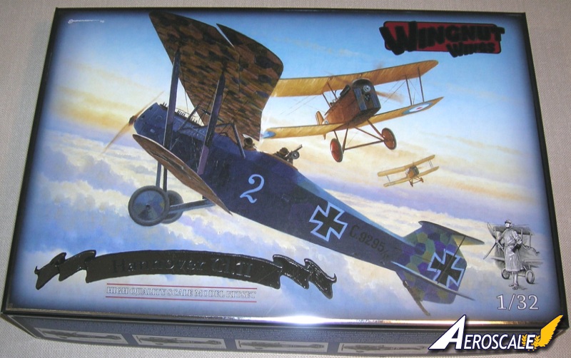
The WNW Christmas line-up usually has some fine releases and this year seems their most impressive yet.
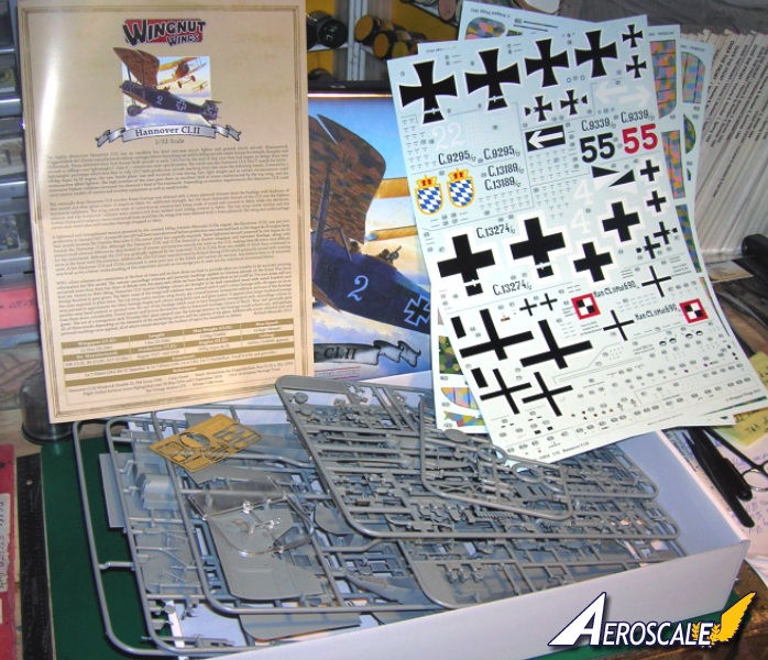
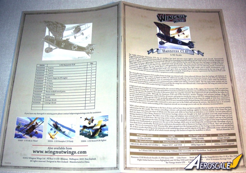
Kit Contents
32024 1:32 Hannover Cl.II US$99.00
-2 seat fighter and ground attack aircraft.
-261 high quality injection moulded plastic parts.
-16 photo-etched metal detail parts.
-32 page fully illustrated instruction manual.
-3 high quality Cartograf decal sheets with markings for 5 aircraft;
The build
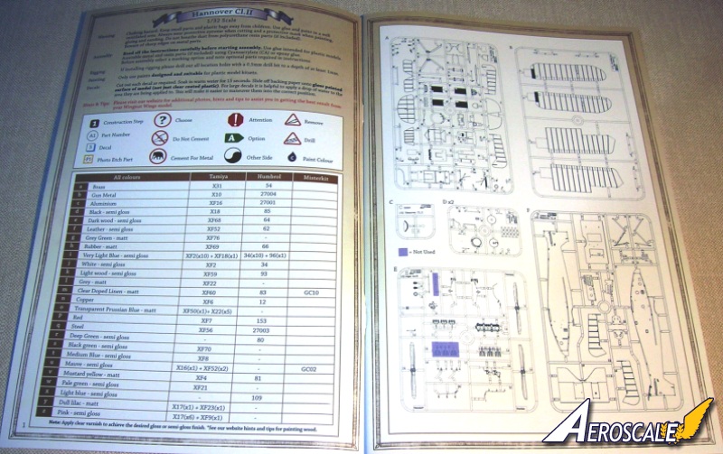
Page 1 First we start with the typical WNW general instructions & colour matches for paint. Note that there are several good decal sheets available now that replicate the contrasting wood grain.
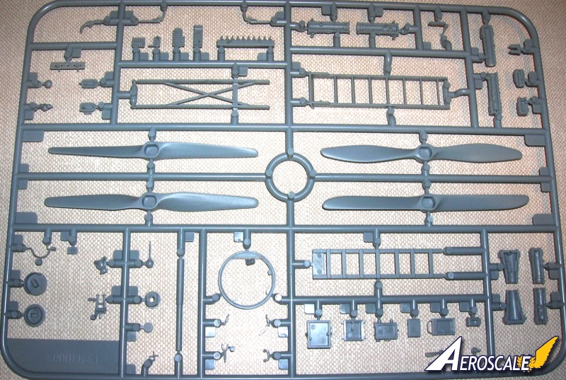
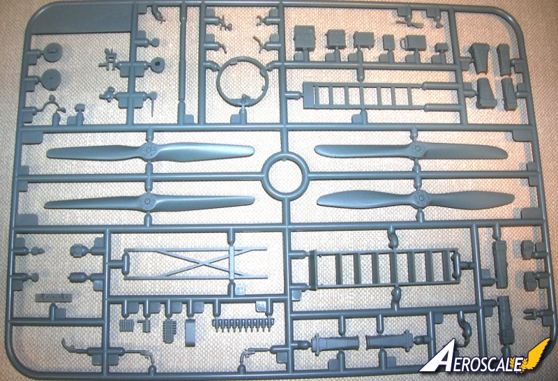
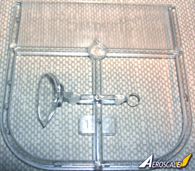
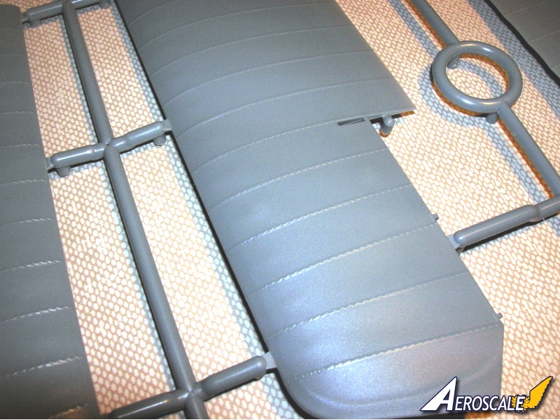
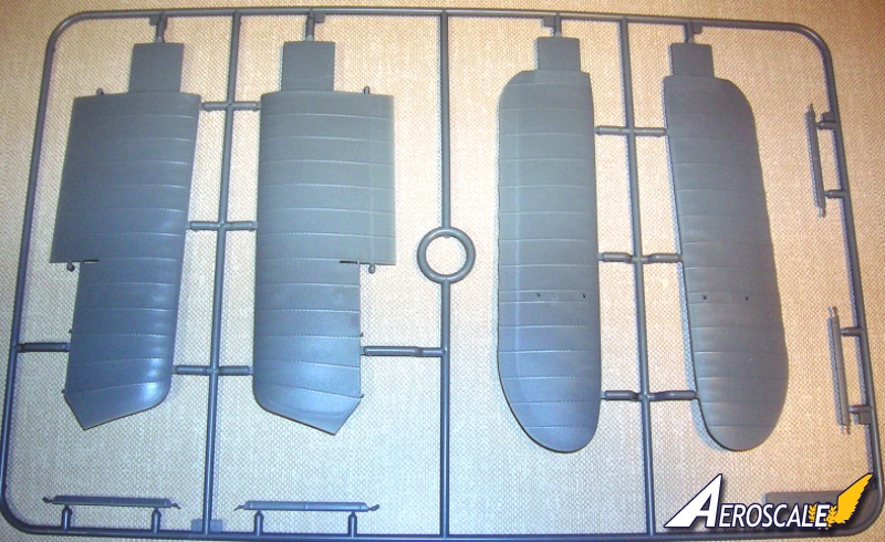
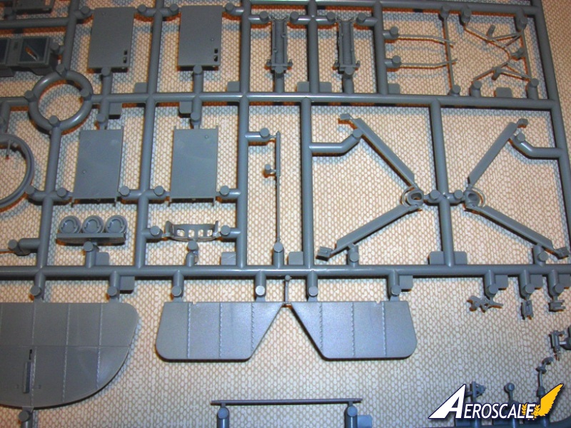
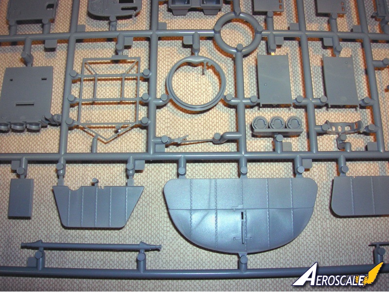
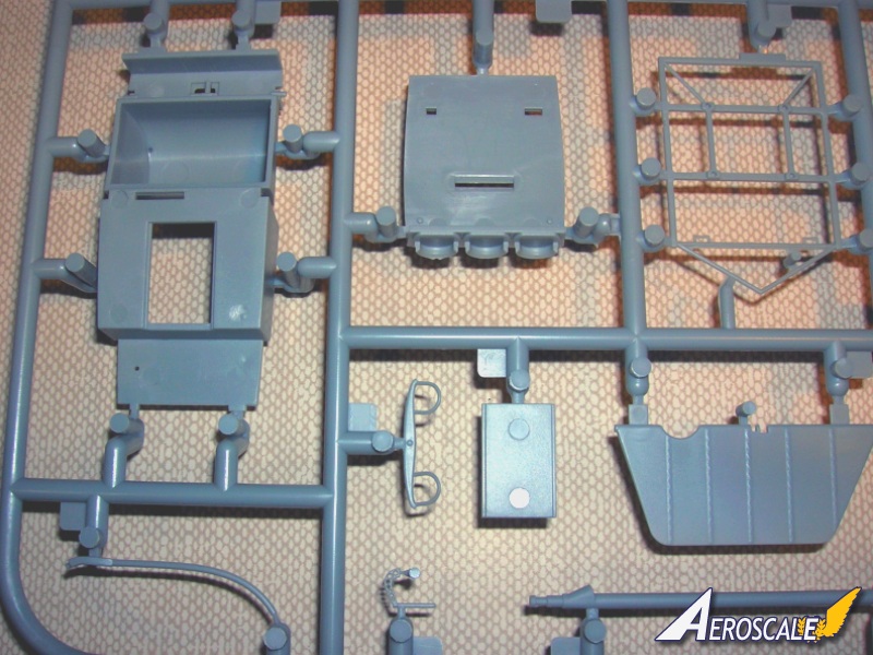
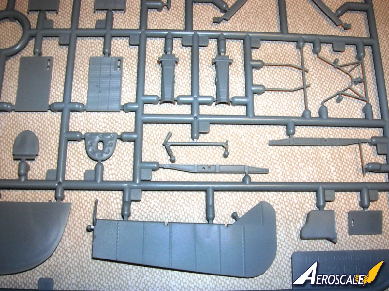
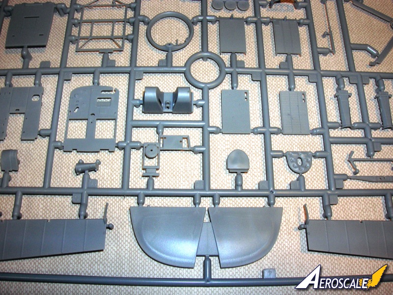
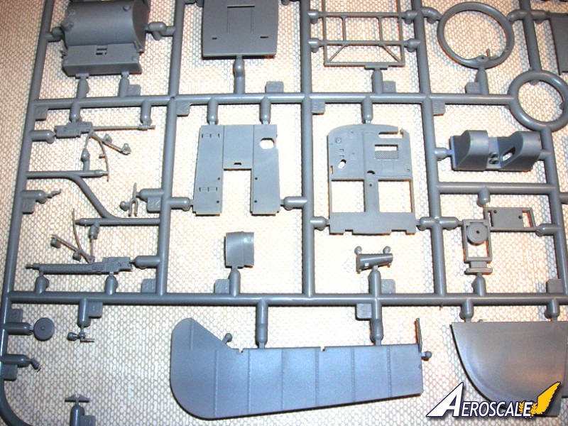
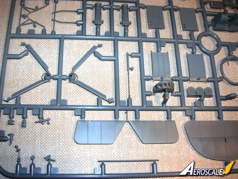
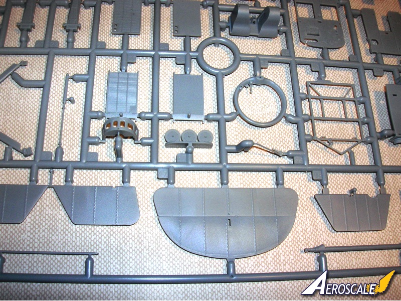
Page 2 We find the parts maps.
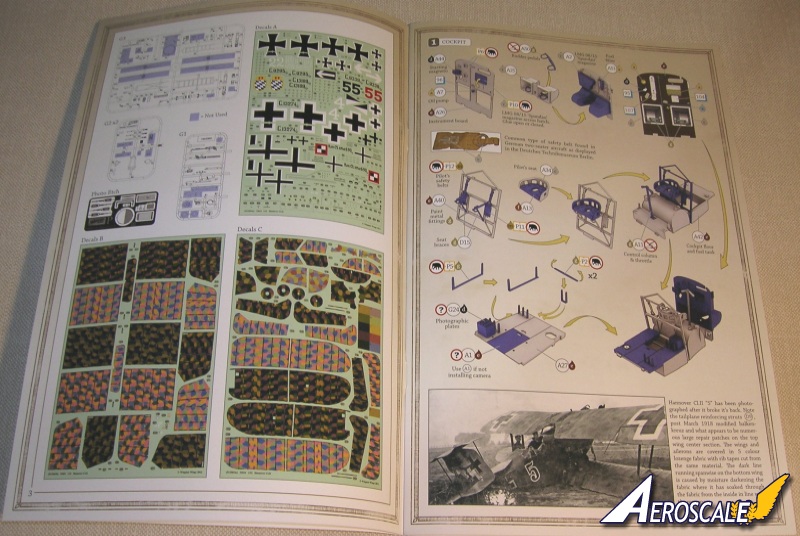
Page 3 shows the maps for the six decal sheets and the photoetch fret.
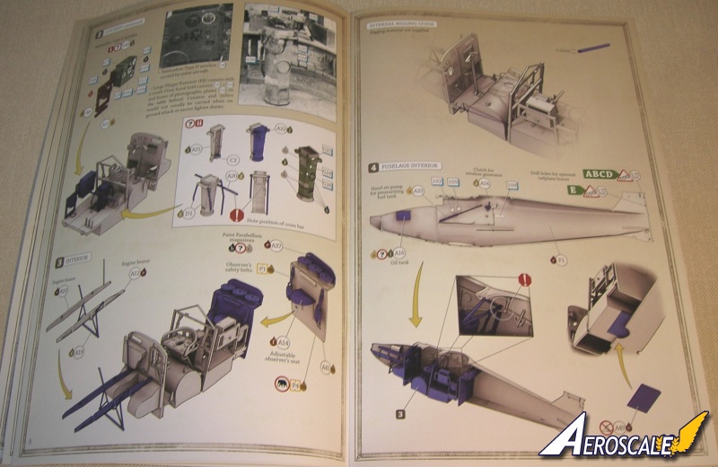
Step 1. The Cockpit.
The instrument bulkhead (PP A 26) is the first to get dressed out. Beginning with starting magneto (PP A 44), oil pump (PP A 7), selector switch handles (PE P 6 X 2) and ammunition storage hatch (PE P 10). Then on the reverse you add the rudder bar (PP A 50) in its shroud (PP A 25). Next the ammunition storage box (PP A 2) and fuel filter (PP A 51). See page 7 for some colour notes. Note the unbleached canvas colored lap and shoulder harness for the front ( and later rear) cockpit. Lay your color down then put the buckle portion face down on a fine grit sanding film. Rub gently back and forth several times. When you pull the part up the raised brass relief will show brightly. Attach these to the frame work (PP A 40 & D 15 X 2) that will also support the pilots seat (PP A 34). Add these to the combination cockpit flooring & fuel tank (PP A 42) along with the control column (PP A 11).
Now the next bit needs some study, The six supports that are attached to the floor are 3 separate part. One long piece (PE P 5) that enters from under the rear cockpit flooring (PP A 27). Then there are 2 short ones (PE P 2) that attach to the top surface of the same flooring. With several detachable rods with wingnut caps these items could be used for additional Parabellum ammunition storage. There is a separate floor plate (PP A 1) that completes the floor covering if a camera is not installed.
Step 2. The cockpit continued.
The radio antenna reel (PP A 8) is secured to the support frame (PP A 15) along with the D type wireless transmitter (PP G 49). In a protection flight seldom did any of the assigned escort aircraft carry cameras or transmitters. Yet when they flew attack missions there were aircraft that were assigned to carry specific equipment. The red & white i & ii denote options. Note the caution to place the horizontal support bar and thus orienting the camera in the right direction. See page 7 for some colour notes.
Step 3. Interior.
This is really about assembling the engine supports (PP A 10, 12 & 19) and the rear cockpit back wall (PP A 41). Here we add the lap belts top the rear cockpit, adjustable observers seat (PP A 14) and the standard supply of Parabellum ammunition drums on a shelf (PP A 37).
The internal rigging guide is next and notes the path for the elevator cables.
Step 4. Fuselage interior.
This discusses the oil tank (PP A 16), the fuel pressure hand pump (PP A 33) is typical for a two seater machine ands has the knobs for the pilot & ther observer to operate. The clutch for the wireless (PP A 54) allowed that it could be engaged to transmit only when needed. The secondary floor hatch (PP A 49) can be added in the open or closed position. WNW cautions not to use glue here. Just a quick note the pilots right fuselage side is PP F 9 not F 1. Note also some holes that need to be drilled. The add the assembly from step 3.
Page 7 has is the painting guide for the interior.
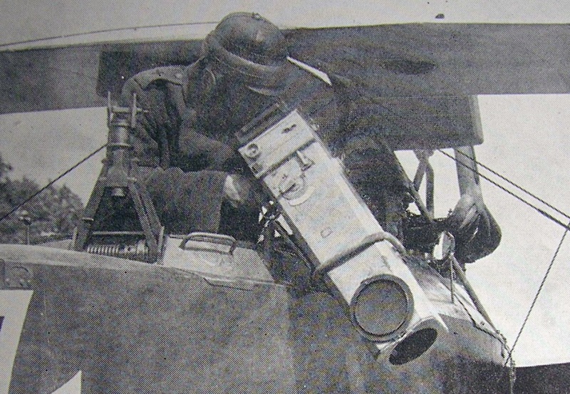
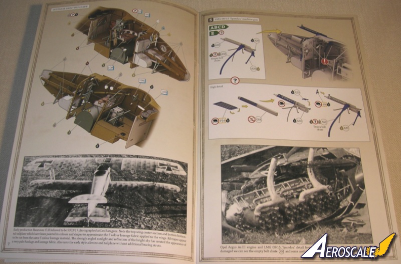
Step 5. LMG 08/15.
The Maxim (pilots) machine gun. This is a very easy assembly of the Maxim gun (PP A 30) and detailing with the fretted gun jacket (PE P 14), cocking mechanism (PP A 29) and forward sight / jacket end cap (PE P 8). There is also the elongated empty chute and rear gun support (PP A 39).
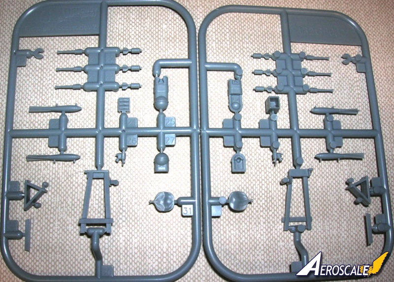
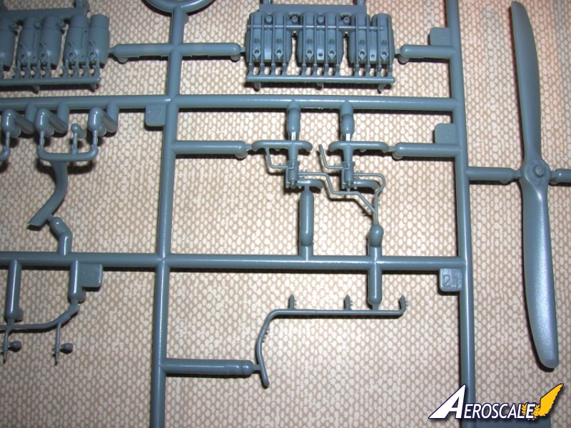
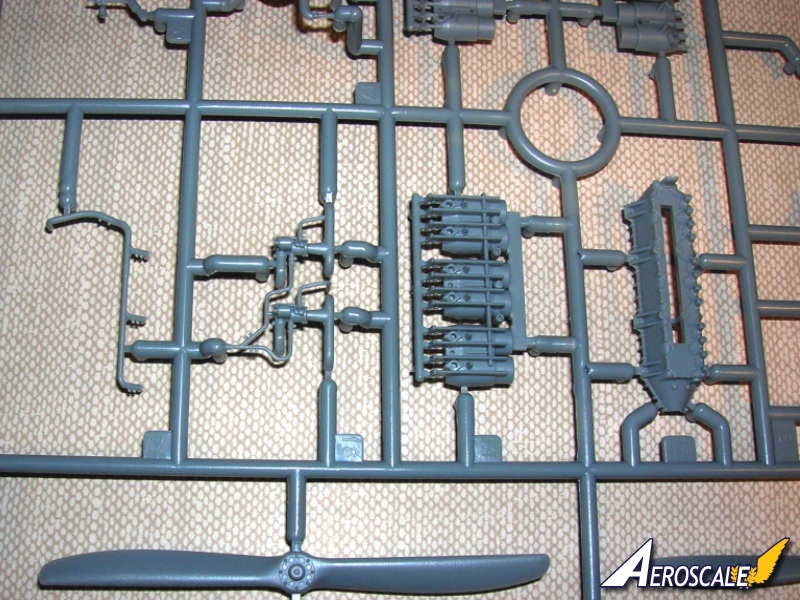
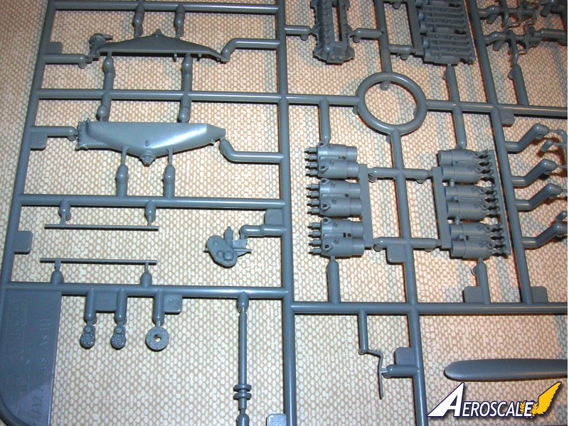
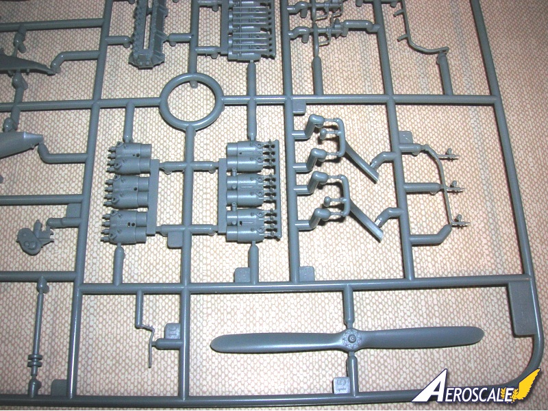
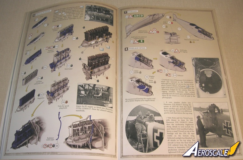
Step 6. Opel Argus As.III.
This engine was used in the Hannover CL.II. Now just by the engine designation of As.III we know this was a motor that had 160hp. When ever the suffix a was added it meant that the motor was up rated to 170-200hp. After 220ph the ratings went to IV and onward. The problem with the Opel Argus As.III in the Hannover CL.II was weight to power ratio. Motors wore out and performance tended to fall off. Usually motors were due for ring & seal replacement after 25 - 30 hours operation. With the need for more motors the Hannover CL.III was given the Mercedes D.IIIa rated at 170-175hp. Finally the Opel Argus AS.IIIa 180hp became available and had the over-compressed pistons with the high performance carburetor employing benzine. It was this motor that went into the Hannover CL.IIIa. The horsepower designations are base on minimal not maximum out put rating. The Hann. CL. II would not have left the factory with the 180hp version. (Note there were some differences in each ariframe design of the Hannover CL.II, III & IIIa that were not engine related).
The kit motor (PP E 1, 2, 4, 5, 6, 7, 8, 10, 11, 12, 14, 18, 20 & 21) comes together in a very easy format. WNW continues to provide a separate (pilots left) bank of cylinders without mould push rods, incase you want to add these yourself. Decals are provided for the government & designation plates. The primer white seen on the exhausts was simply a company procedure.
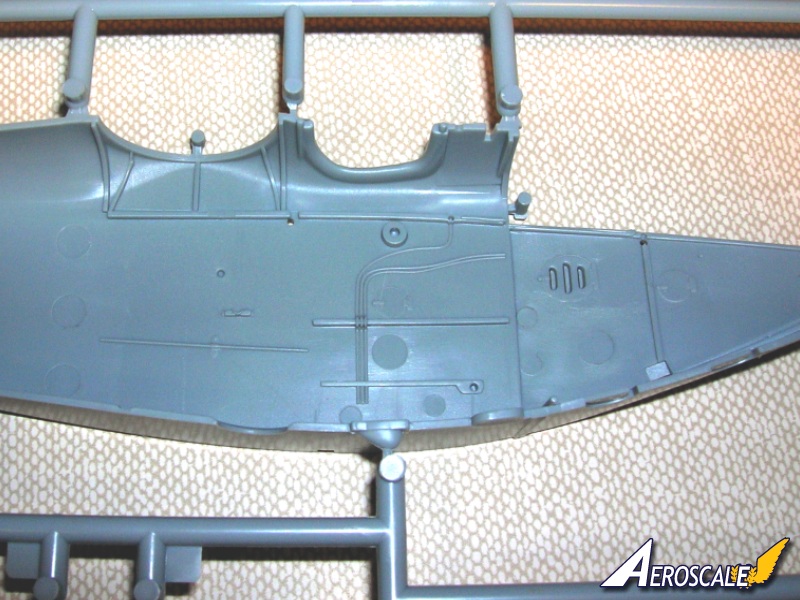
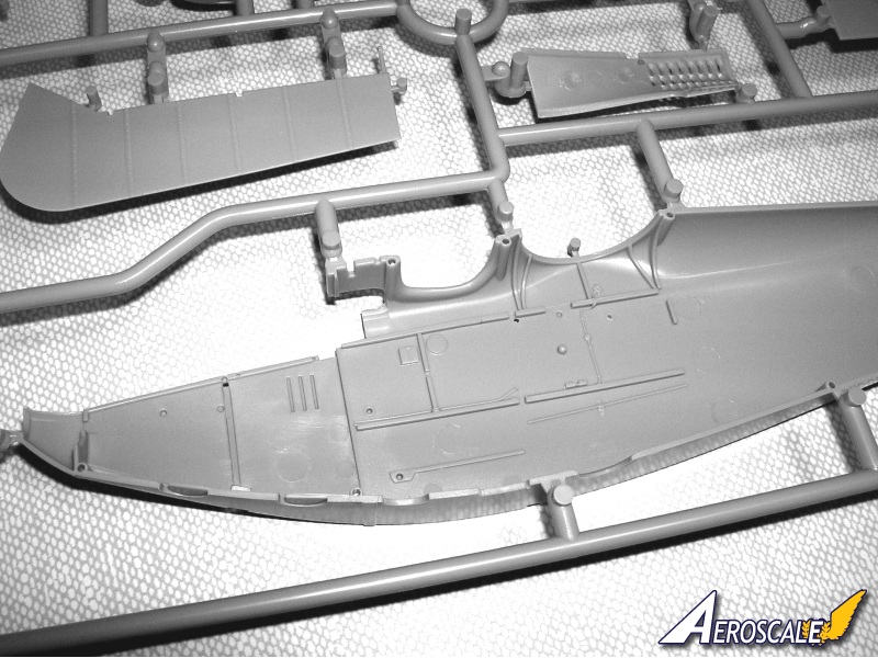
Step 7. Fuselage.
These halves note further holes that need to be drilled. The addition of the spark advance lever (PP A 45) and fuel pump lever (PP A 9) to the pilots left fuselage side (PP F 1) and now unite the fuselage halves (PP F 1 & 9). Then erase the resultant seams.
Step 8. Fuselage continued.
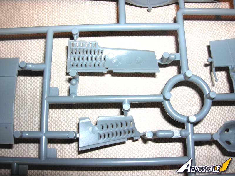
detail continue here with adding the pilots right side engine cowlings (PP F 5 & 8 ) but add the exhausts (PP E 16 & 17) before you add F 8. The striking thing about the WNW engine covers are that the multiple vent ports are moulded as openings.
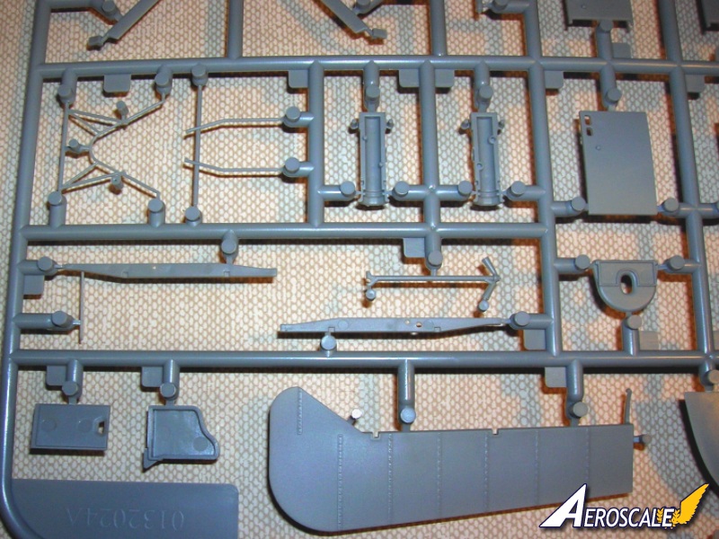
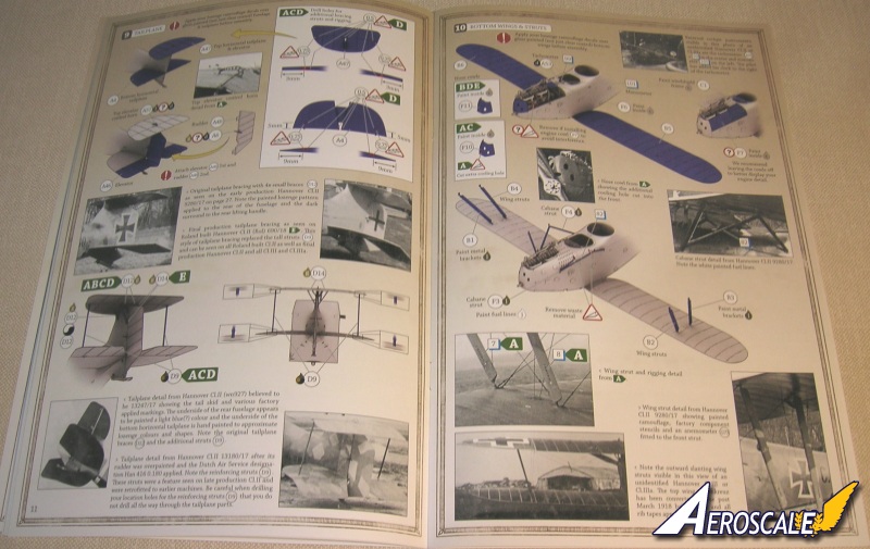
Step 9. Tailplane.
This is a dual whale tail version (PP A 4, 6, 46, 47, 48 & 57). Note the profile you choose to model and include the recommended modifications for support struts (PP D 9 X 2, 12 X 4 or D 14 X 2 ). Scrap & inset views eliminate any doubt what needs to be followed.
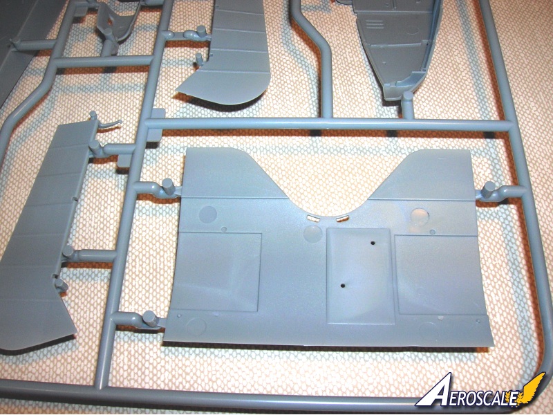
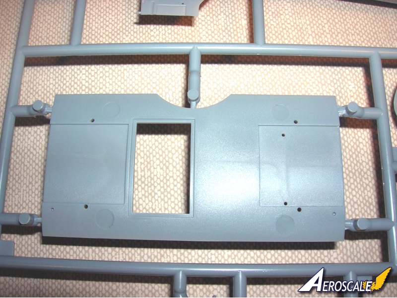
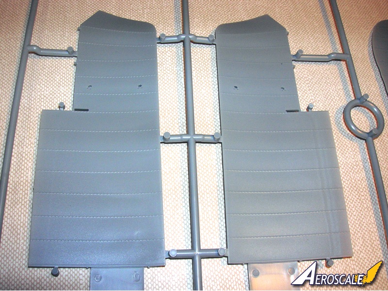
Step 10. Lower wing and struts.
The method WNW uses is very sound & solid. The lower wing (PP B 5 & 6) root tabs are substantial. The engine tachometer (PP A 53) a small engine cover (PP F 6), the larger (pilots left) engine cover (PP F 7) and the nose cowls (PP F 10 or 11). As notes in step 8, the WNW air intake & multiple vent ports are moulded as openings. There is only one you may want to open (for profile A). The cabane & interplane struts are commendably thin and appear to be in-scale.
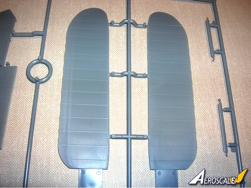
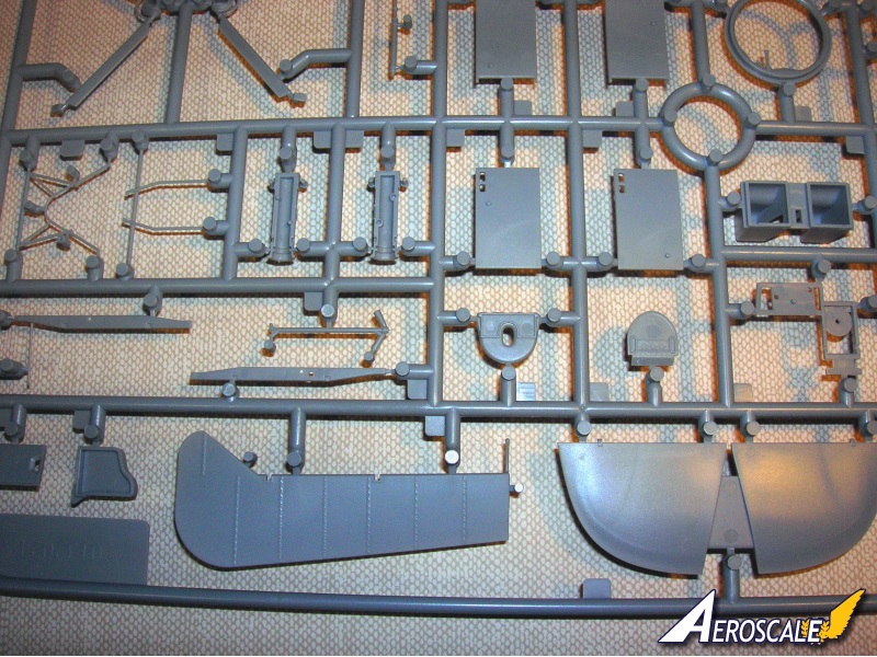
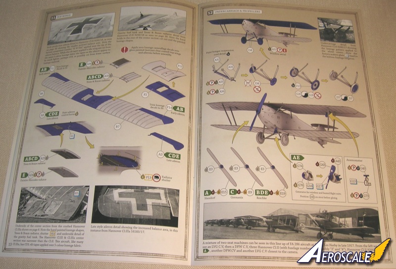
Step 11. Top wing.
These have several options to choose from according of course to the airframe profile you are modeling. Ailerons come in early (PP F 12 & 14) or late (PP A 3 & 5) production versions. The radiators come in either the Daimler - Mercedes type (PP A 24 & 36) or the Teeves & Braun (PP A 23 & 35) versions. The radiator shutter (PE P 13) is a half moon plate that rotates in a ring to cover the radiator under-surface for heat retention in colder weather. Or it could turned in the ring to be opened in hot weather to allow the heat to fully dissipate.
Since rigging is an issue of some concern for the newer builders, I will include a brief description here. Since you should have pre drilled all rigging holes and have chosen a scheme that you want to apply to your build this is a good point to start your rigging process. First apply paint or lozenge decal to the upper-surface of both lower wings - only. Next apply paint or Lozenge decal to the under-surface of the top wing - only. When thoroughly dry unite the fuselage and wings in a jig to line up all aspects of your assembly. Next chose a smoke gray tinted invisible sewing thread available at any sewing center. Look for thread that is about 0.15mm The advantages to the smoke gray is that it catches light much the same was as metal cable does in differing angles and attitudes. Anchor your rigging thread through the pre-drilled holes on one end only to start. Put as many lines as needed through one hole and anchor one end only. Yes, I know Im repeating myself. Start with the holes nearest the top wing undersurface locator holes for the top of the cabane struts. NO rigging holes should go through any portion of the Strut Ends or the strut locator holes themselves.
Generally speaking work From the starting point cabane struts out and down to the point where all your rigging line ends are pushed through their end holes in the lower wing. The attach common wooden spring loaded clothes-pins to each loose end. This will draw the threads tight now simply touch liquid super glue to the last hole and wait to dry. Use a sharp #11 razor knife to clip the ends after their dry. Clean up is much easier on the unfinished wing surfaces. Finally apply color or decal to these areas. That should help you get started. A little planning is very important to your overall success. Use wooden spring loaded clothes-pins not medical clamps.
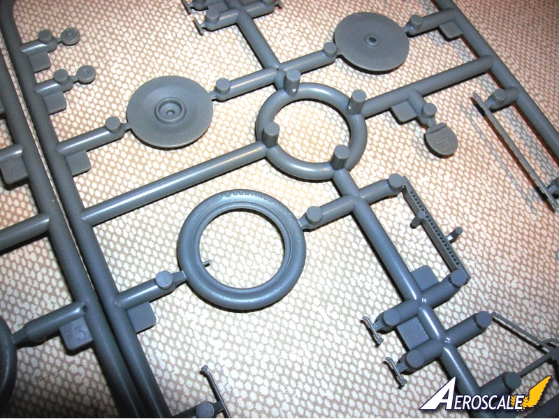
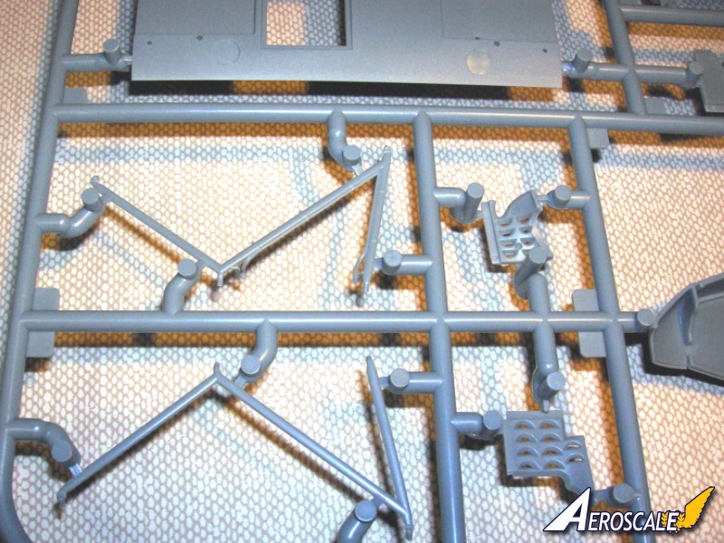
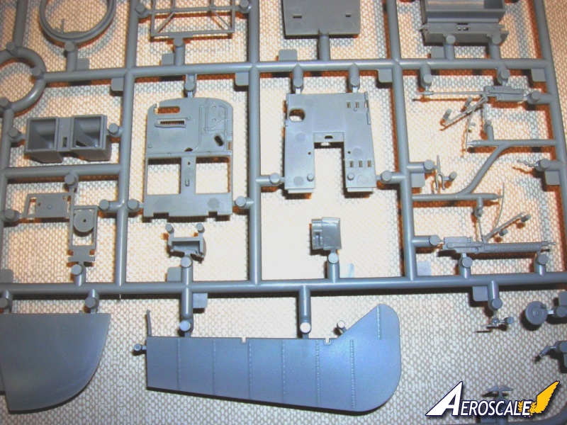
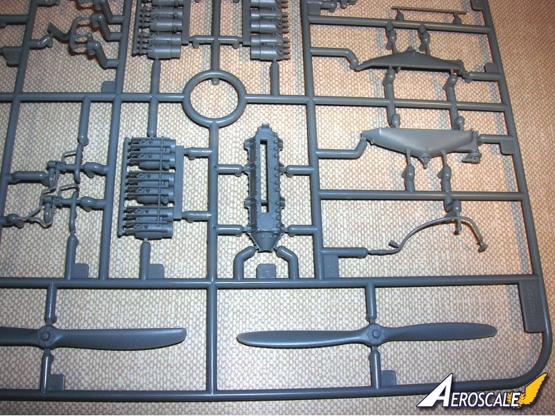
Step 12. Undercarriage & propellers.
The undercarriage is a typical set of vee-leg struts (PP A 31 & 32) axle (PP A 56) and it lower shroud (PP A 55). Wheels with inner faces (PP D 8 X 2) retainer clips (PP D 13 X 2) and outer covers (PP D 7 X 2). The weakest part of a Veestrut landing gear assembly in plastic is the side to side twist. This causes the gear legs to buckle & bend. I use upholstery thread to wrap around the lower legs of the landing gear with the axle in place to simulate the bungee shock chords. This looks like the original and actually assists in securing the axle in place. The external generator (PP A 43, G 43, 74 & 76) as noted provided power for the wireless and heated flight suits. Propellers are provided representing those from Niendorf (PP E 15), Germania (PP E 9) & Reschke (PP E 19 ). Another external piece of equipment was the Anemometer air speed indicator (PP G 40 & 73).
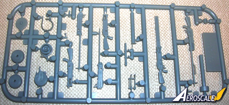
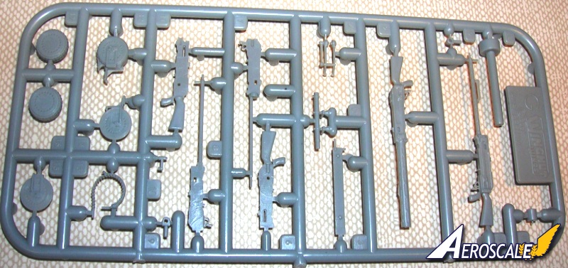
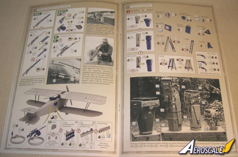
Step 13. Observer armament and final assembly.
The Parabellum guns are easily dealt with and build up quite nicely. You have the choice (according to the profile you are doing) of the LMG 14 (PP G 2 & 3) all plastic gun, or the high detail build (PP G 5, 6, 7 & 10) (PE P 3) or the LMG 14/17 (PP G 1 & 50 (PE P7). Gun ring, flares, grenades & racks are provided to adorn the external areas of the fuselage.
Step 13 continued Optional accessories.
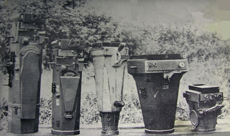
These items are fit for detailing especially within a diorama structure. 4 cameras, box of photo plates, barograph, first aid box, homing pigeon box, wheel chocks ladders, trestle / saw horse, flare guns and a mascot Teddy bear.
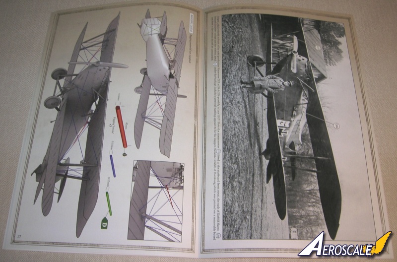
Page 17 Rigging diagram. This shows the machine in rear quarter and front quarter views.
Page 18 Full page image of Hannover CL.II of FA (A) 254.
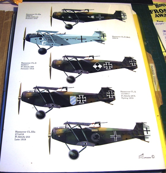
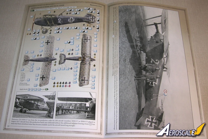
Decal profiles
Page 19 -20. A. Hannover Cl.II 9295/17 White 2, Ltn. Ruhr(?), FA A 286b, late 1917.
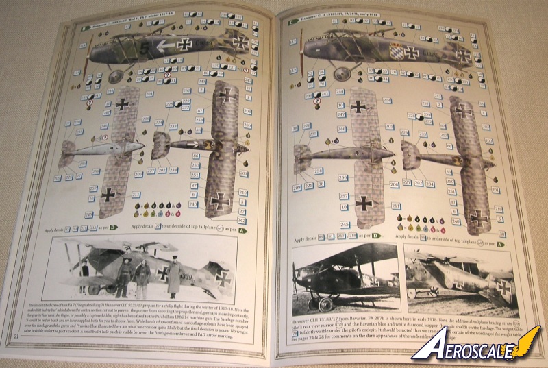
Page 21. B. Hannover Cl.II 9339/17 Red 5, FA 7, winter 1917-18.
Page 22. C. Hannover Cl.II 13189/17, FA 287b, early 1918.
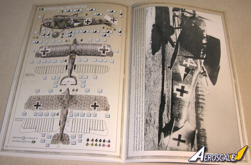
Page 23-24. D. Hannover Cl.II 13274/17 White 4, Schlasta 25, mid 1918.
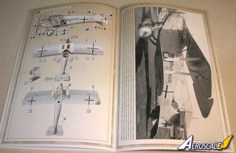
Page 25-26. E. Hannover Cl.II (Rol) 690/18, FEA 8, late 1918.
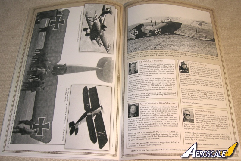
Page 27-30 Real photo images
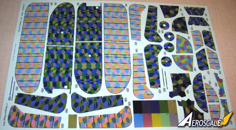
Camouflage lozenge fabric decals
Three sheets! Cartograf, registration is as close to "painted on" as you will see in waterslide decals. It is impressive is the way overlapping markings are grouped as single decals. This is something we have seen on other Carograf sheets and seems to be one of their hallmarks.
The sheets that are devoted to lozenge fabric decals, have both 4 and 5 colour patterns in "cookie cutter" types to make for easier application. A nice addition is patches of each colour for spot repairs. The colours of the lozenge camouflage decal have been dealt with in past reviews here at Aeroscale and it can be said that they are still good overall and I would include texturing even as they themselves have allowed to be done on their display models. Note since the four colour did not become available until the Spring of 1918, this gives you a time-line that a machine was photographed in.
References
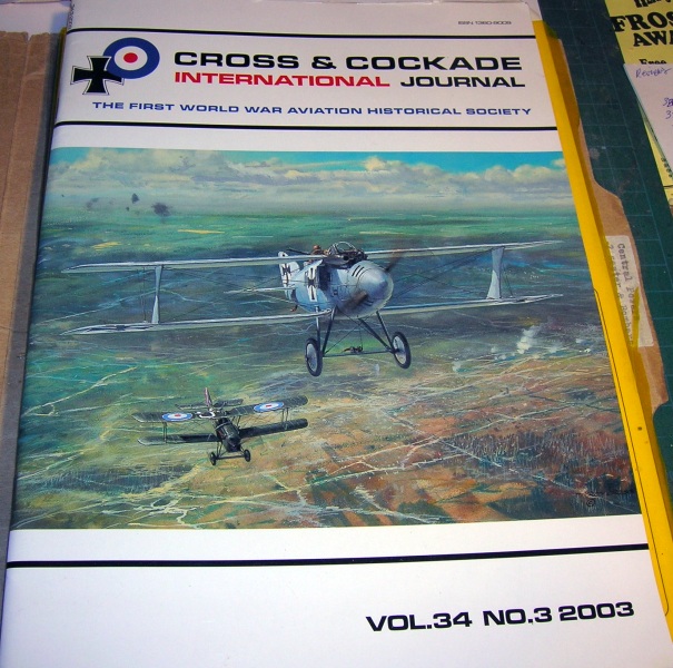
Cross & Cockade
USA Vol. 3, #2 Pp.124-137, 1962 Summer.
USA Vol. 9, #3 Pp.257-262, 1968 Fall.
USA Vol. 10,#1 Pp.62- 65, 1969 Spring.
USA Vol. 14,#1 Pp.65- 71, 1973 Spring.
USA Vol. 18.#3 Pp.230-235, 1977 Fall.
USA Vol. 19,#3 Pp.266-274, 1978 Fall.
USA Vol. 19,#4 Pp.360-369, 1978 Winter.
USA Vol. 20.#2 Pp. 97-106, 1979 Summer.
USA Vol. 22, #3 Pp.266-271, 1980 Fall.
USA Vol. 24, #1 Pp. 83- 84, 1982 Spring.
USA Vol. 25, #3 Pp. 1983 Fall.
Intl. Vol. 34 #3 2003.
German Army Air Service by R. Rimell, Vintage Warbirds # 2, Osprey Pub.1985.
Hannover CL.II-IIIa by R. Rimell, Windsock Datafile #23.
Pictorial History of the German Army Air Service by A.Imrie, Allan Pub. 1971.
Sclachtflieger! by Duiven, Rick; Dan-San Abbott, Schiffer Military History. ISBN 0-7643-2441-1. 2006.
World War One in the Air by Rimell, Arms & Armour Press, Warbirds #9, 1988.
When contacting retailers or manufacturers, please remember to mention that you saw their products highlighted in review here on Aeroscale.
Highs: The usual high standard of WNW details and design. Decals are impressive, sharp and in register. Instructions well done.Lows: Minor typos in the instructionsVerdict: This is another great kit from WNW with a bit of something for every builder. Novice or experienced you cannot go wrong with this kit.
Our Thanks to Wingnut Wings! This item was provided by them for the purpose of having it reviewed on this KitMaker Network site. If you would like your kit, book, or product reviewed, please contact us.
About Stephen T. Lawson (JackFlash) FROM: COLORADO, UNITED STATES
I was building Off topic jet age kits at the age of 7. I remember building my first WWI kit way back in 1964-5 at the age of 8-9. Hundreds of 1/72 scale Revell and Airfix kits later my eyes started to change and I wanted to do more detail. With the advent of DML / Dragon and Eduard I sold off my ...
Our men "Kornbeef" & "McGunns" both comment.
". . .WNW seem to have got the aileron decals swapped over, the top has the gaps for the arm and cable point, the underside doesnt. Not a difficult fix given the spare lozenge ribtape included."
Another modeler has weighed in on his build.
"When I glued the fuse halves together, the tail area join was skewed by a fraction of a millimeter. However, with WNW's legendary tolerances, this totally threw off the angle of the stab slot. I had to gouge the slot out on one side and eyeball it into the correct angle.
Another was the radiator pipe that comes from the upper wing and goes all the way to the bottom of the engine sump. I snapped it off when trying to align it into its slot (of course, the fuse was already joined by this point). So I had to ream out two of the fuse bottom access ports, shine a bright light into one, and use the other to tweezer and glue the pipe end back into place. I really could have used a nurse mopping my brow during that "operation".
Third major muff-up was snapping off one of the wing strut connector points (KNEW that was gonna happen). I reattached it with a tiny length of .3mm piano wire. Greatly strengthened it, and it gave me some flexibility to work with while I tried to get the da*@n thing into the slot."
As a matter of fact, he has expressed an interest in doing such a feature. He is traveling on a business trip at the moment but will get back to me in 24 hours. I also e-mailed him the link to our Features page and he seems properly chuffed.
I have this kit in my build queue under "next" - it's certainly a big bang for your buck... There are not many kits that offer a "simple" scheme (Roland built) to hand painting lozenge + lozenge wings.
I'll be building option "A" - look towards mixing 4 and 5 color lozenge on lower and upper wing planes


Comments