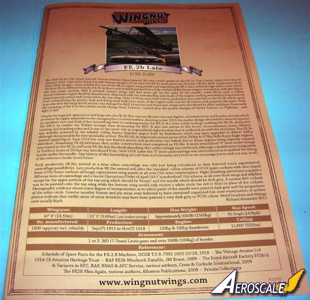
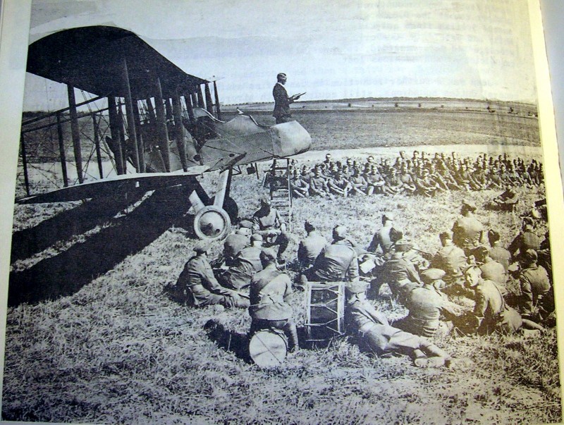
The Royal Aircraft Factory F.E.2 was a two-seat pusher biplane that was operated as a day and night bomber and as a fighter aircraft by the Royal Flying Corps during the First World War. Along with the single-seat D.H 2 pusher biplane and the Nieuport XI, the F.E.2 type was considered instrumental in ending the Fokker Scourge that had seen the German Air Service establish a measure of air superiority on the Western Front from the late summer of 1915 to the following spring.
Arriving at the front in late in 1915, the FE.2b was initially used with marked success and helped to win air superiority for the first Battle of the Somme. The installation of the 160hp motor increased the span of life for the type, but it was hopelessly outclassed by the close of 1916 and was finally withdrawn from daylight operations early in 1917. Re-issued later that year as a night-bomber, it continued to be used until the end of the war. Found to be particularly suited to this role the FE. 2b was used extensively by Home Defense Squadrons for anti-Zeppelin patrol, often with 'exhaust manifold silencers' fitted to the exhausts and Michelin reconnaissance flares carried on fuselage-mounted racks.
The kit
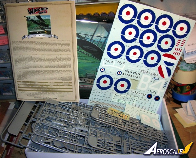
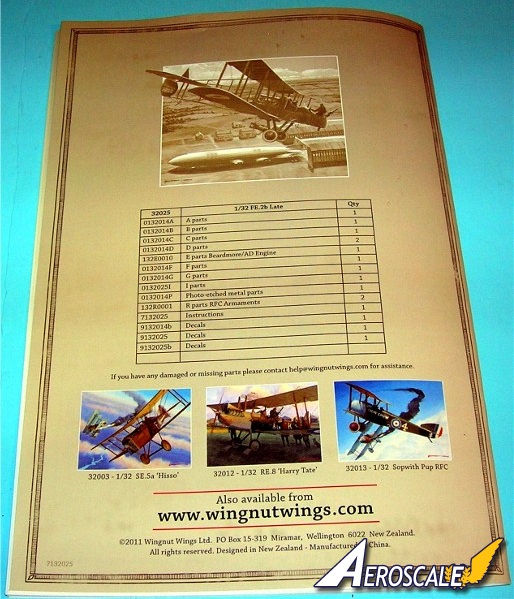
The FE.2b. The kit arrives in the typical WNW deep, top-opening heavy box. No space is wasted at all, and it's packed to the top with 11 individually cellophane bagged sprues, plus accessories. The kit contains:
328 x grey styrene parts (20 not used)
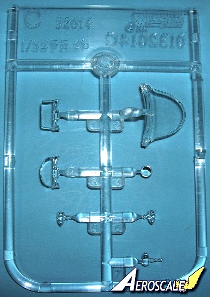
7 x clear styrene parts
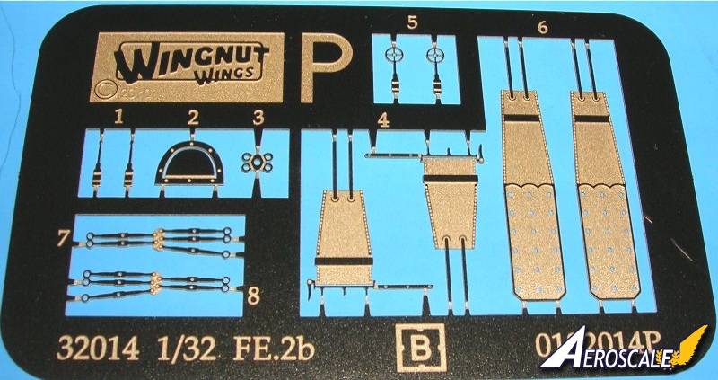
12 x etched brass items
Decals for 5 x colour schemes
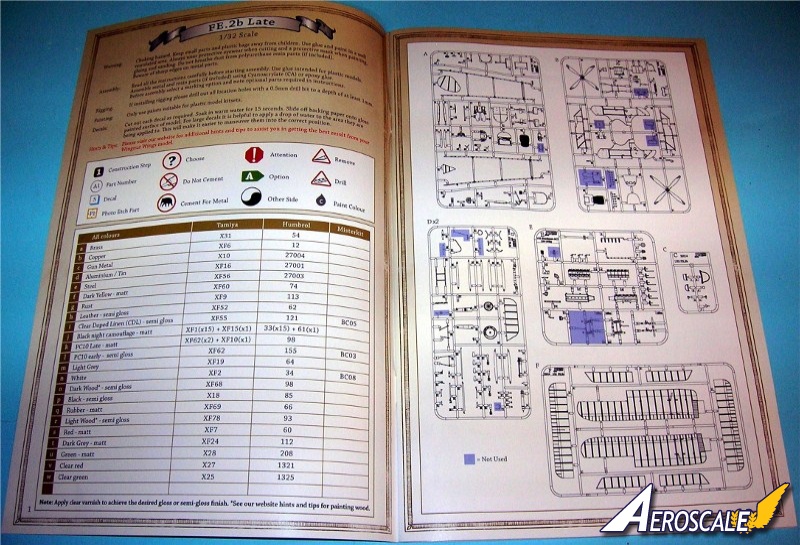
A 34 page instruction booklet
The moulding is all we have come to expect from WNW high level of quality control. There is no flash and clean-up of the light mould lines is an easy task. I recommend flex files for this. The ejector-pin scares are out of sight after assembly. The ones on the floor sand away easily. The few heavy ejector-pin scars are easy fix. The surface finish and moulded panels are very impressive. The depiction of the ribs and stitching on the wings and tail surfaces and the nacelle with wrinkles both inside and out gives you the impression that this kit was thoroughly researched before it came into existence.
The Fit
There is not a lot you can dry-fit in a kit of this configuration, but like our managing editor, who did the basics of the nacelle and lower wings on the early production version, I too went the distance and clipped a few parts from the trees. The wings are impressive, they span of 18" (about 46 cm), mostly moulded solid. I dont know of any manufacturer that could pull off these as straight. From leading to trailing edges they look the part. The nacelle is almost to scale in appearance that will surround an interior framework that not only provides rigidity but holds the scale 24 gallon main fuel tank firmly in place. The tank traps the lower wing roots and is designed to make the wings sit correctly. The cyanoacrylate glue joints will require an accelerator to bond thoroughly. I would add a brass rod to pin the joint in the wings' roots.
instructions
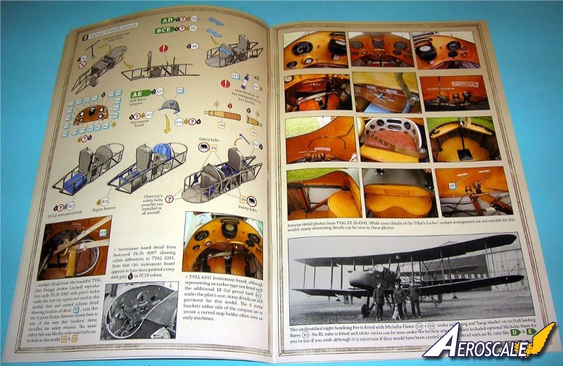
The instruction makes great reference to the aircraft type. Something no kit manufacturer has been able to provide before. There are highlighted diagrams noting placement of subassembly additions. Reference images of the fine details. Captions accompany the diagrams and images, with parts specifically named serving to inform you about the build and the original aircraft as you move from page to page. Colour matches are for Tamiya, Humbrol and some Misterkit paints and noted in every step.
Recommendations.
Read and re-read and re-re-read through the instructions studying each page from start to finish. There are so many options to the profile you may want to build it may take you scribbling some notes to yourself to keep it all straight. Just doing this review I have gone through it eight times.
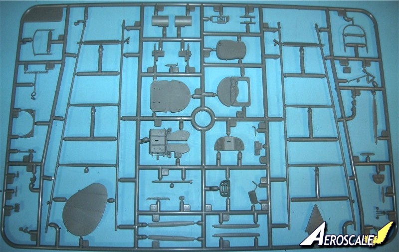
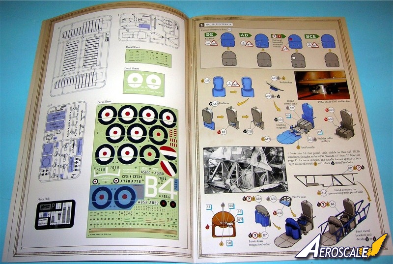
Nacelle interior
Steps 1 - 4. Note the options. The pilot sits over a 18 gallon fuel tank . The observer / gunner is to sit on the Lewis gun ammunition stowage (A 18 & B 7) bin. The observers flooring (A 17) has four possible modifications. The radiator (A 13 & B 28) complete with the appropriate plumbing sits on the bulkhead. There are two styles of lids (B 1 or D 18 X 2) for the ammunition stowage (A 18 & B 7). The instrument panel (A 22) is curved like the original and the bezels are moulded in relief. There is a Mk.II compass (A27) and each gauge has a corresponding decal face and information placards for the panel. There are options such as the Sterling wireless set (A 14 & 24), wireless antenna reel (A 20) Morse code transmitter (A 28) and finally a tube for flares (A 24).
The pilot's seat (A 35 & 42) features a padded cushion (A 42). The curved separator/back-rest (A 23 or 24) between the cockpit and engine compartment is a good fit. Never mind the seams left at the ends. These were on the original. Photo-etched brass lap harnesses (P 4 & 6 X 2) are provided for the pilot and gunner positions.
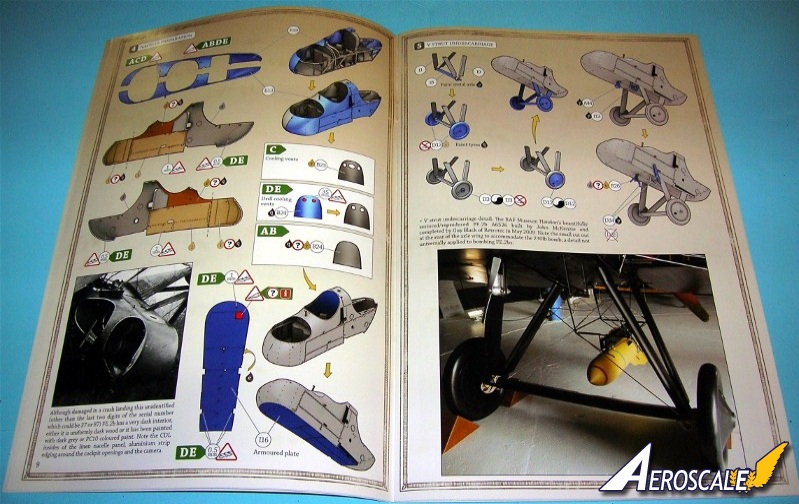
Step 5. The undercarriage can be built as the Trafford Jones modified style. The wheels covers (D 12 X 2, 13 X 2) feature a spoke effect and Palmer Cord logos on the tires (decals are also provided if you prefer). The pilots step (I 13) would have been better as a photo-etch item. The exposed end of the antenna reel (A 44) is a nice touch. The wireless generator & propeller (R 26) and elevator actuation horns (D 34 X 2) are mismarked on the trees but corrected in the instructions here.
Step 6. Details the positions for the No.4 Mk. 1 Swiveling Mount (A 32) and the No.10 Mk.1 Anderson rear mount (A 7 & D 42).
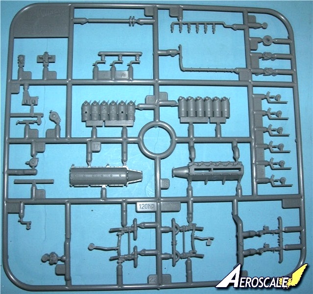
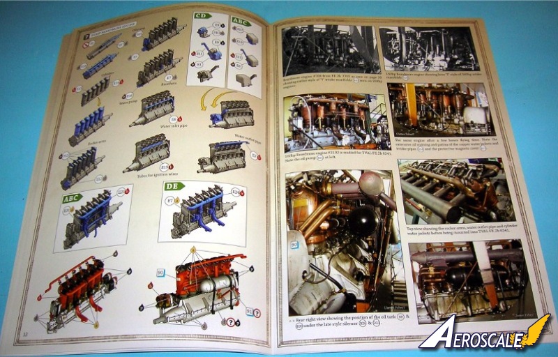
Beardmore Engine.
Step 7. Twenty-nine parts are offered to form a finely detailed engine that can be completed as either the 160hp version, complete with a choice of open or shielded magnetos and etc.
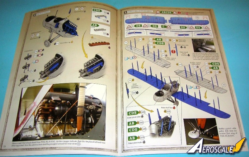
Step 8. Here the completed engine from step 7 is installed along with the radiator scoop / shutters (A 2 & 3). These are mismarked on the trees but corrected in the instructions here. Next the 3 gallon oil tank (B 8 & 20, D 46 & 47). The alternative style exhausts come as either early (B 25) or late (B 26 & D 31 X 2) types.
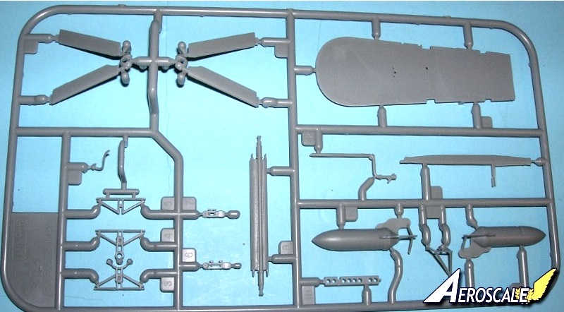
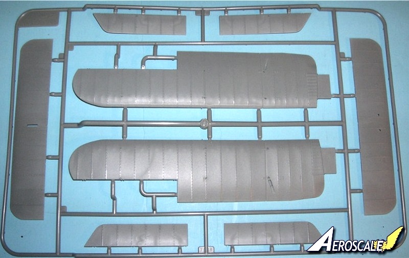
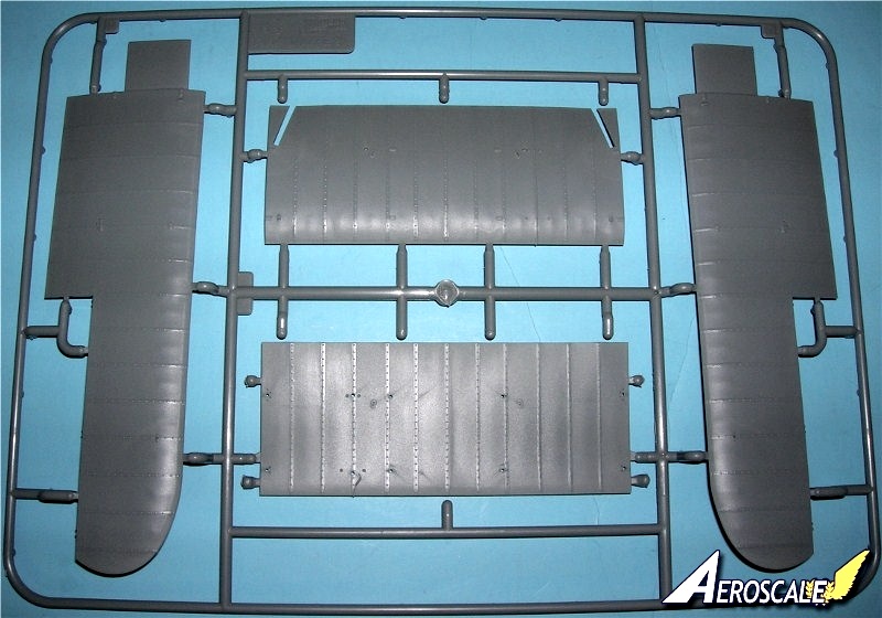
Wings.
Steps 9 & 10. As noted earlier, the lower wing panels (F 4 & 6) are moulded solid. The upper wing has solid outer panels with the center section split into top and bottom halves (G 1-4). There are a few ejector pin stubs to clean off before you can assemble this, but the trailing edge is beautifully thin (be careful not to distort it with too much solvent or heat generating binders. Avoid large amounts of accelerator here). The generous locating tabs will give sturdy joints to maintain the dihedral of the outer panels. The pipes (B 2 & I 2) for the tear-drop gravity tank(s) (D 22 & 23 X 2) connects to a moulded-on extension running down the forward cabane struts (A 40 & 41).
Struts
The interplane struts (D 14 X 4, 10 X 4, 21 X 4 & I 15) and aileron struts (A 26, 38-41) have detailed moulded fixings, and asbestos wrapping on the one nearest the exhaust manifold (b 22). Even with all the locating and rigging holes drilled this configuration will take patience even for those already familiar with simpler biplanes.
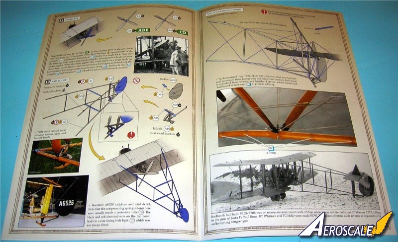
Propeller.
Steps 11. You have a choice of two slightly different 4-bladed props (B 6 or 18) , with a selection of Lang, Boulton & Paul logo decals. Both have only the slightest mould lines to clean up.
Tail Booms & Control Surfaces.
Steps 12 & 13. The tail booms (A 1 & 6) are classic in design. This goes back to Revell's 1:72 DH 2 tail booms. The vertical struts (D 30 X 2) are angled into the airflow. Once again all the rigging holes are pre-marked, with miniature "eyelets" next to each strut. Paint as much of the booms as you can while they're still on the sprues. Keep all joint contact points clean and clear from paint.
The completed booms plug into sockets on the upper and lower wings from steps 9 & 10. The stabilizer assembly has solid locating pins but the rudder is theoretically moveable. I am not a large fan of moveable parts. I would lock it in place for strength.
The ailerons and elevators are separate, but are best fixed with brass pinning. The ailerons feature cable pulleys (D 15 X 2)and "Holt landing lights" (C 5 & 6) for two of the colour schemes.
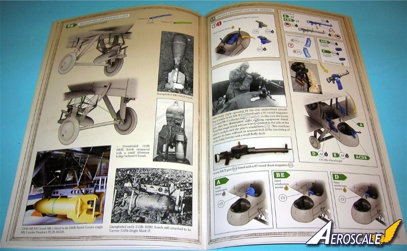
Armament Options
Steps 14 & 15. Assembles the camera, weapons stores and cradles.
8 @ 20lb HALE bombs and their racks
8 @ 20lb Cooper bombs and their racks
2 @ Michelin parachute delivered flare case
4 @ 112lb HERL bombs and their racks
1 @ 230lb HE Mk. I bomb and cradle
2 @ Lewis Guns Mk.II (R 15)
12 @ 47 and 97 round magazines (R 21 & 24)
2 @ Mk.II collector bag (D 1 & 2)
1 @ Thornton-Pickard Type C camera (A 10, 12 & C 4)
1 @ CFS Mk.IV bomb site.
Now understand weight loads would only allow for a specific amount of munitions to be attached to the airframe and still be allowed to take off for flight ops.
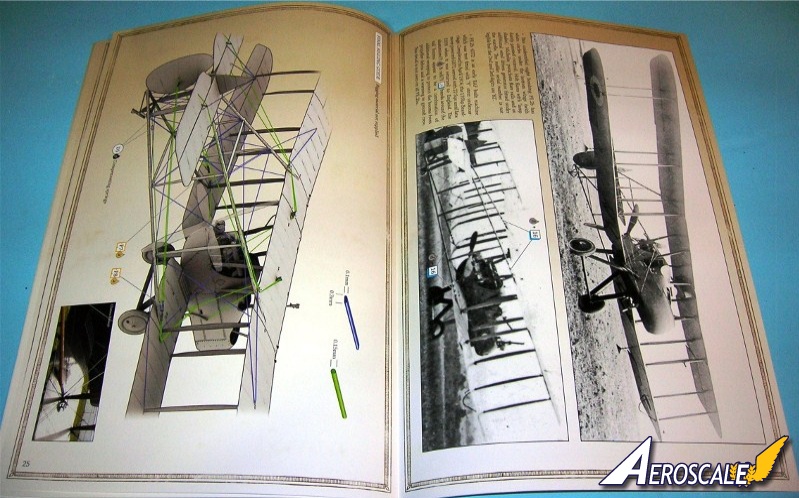
Rigging
This is the first kit I've seen in which three full pages of the instructions (Pp.18, 20 & 25) are devoted entirely to rigging! The diagrams are clear and even colour coded. Yet as with any aircraft model rigging can take up a good part of the construction. It is best to plan ahead and be patient.
Decals
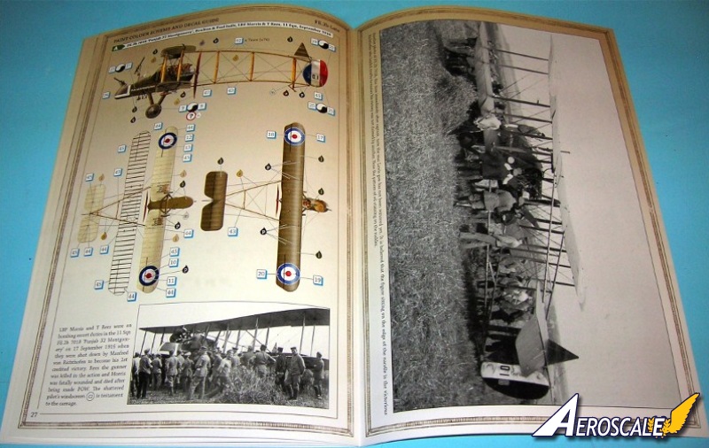
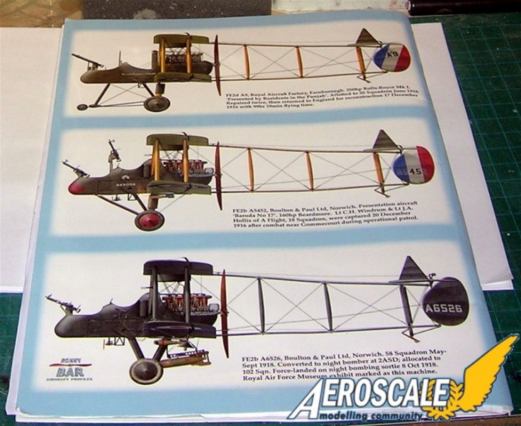
Steps 27 & 34. WNW gives us markings for 5 colour schemes:
A. FE.2b 7018 Punjab 32 Montgomery, Boulton Paul built, L.B.F. Morris & T. Rees, 11 Sqn RFC , Sept. 1916.
B. FE.2b 7666 B4, Boulton Paul built, Training Sqn , June 1917(?)
C. FE.2b A778 Alfred Muller Simpson, G & J Weir built, F.H. McNamara VC & S.J. Hendy, CFS Australia, mid-1918.
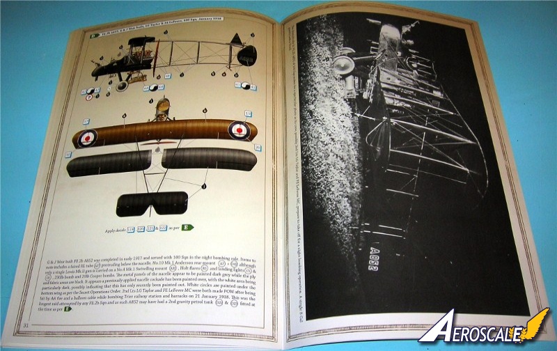
D. FE.2b A852, G & J Weir built, L.G. Taylor & F.E. LeFevre, 100 Sqn, Jan. 1918.
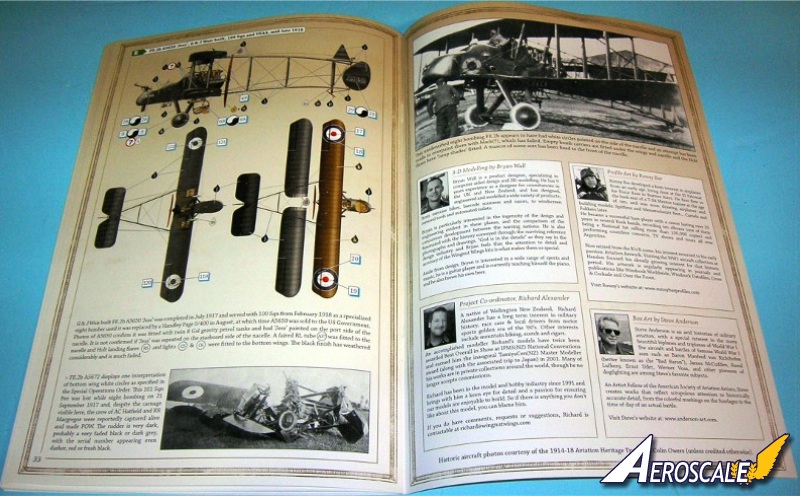
E. FE.2b A5650 Jess, G & J Weir built, 100 Sqn & USAS mid to late 1918.
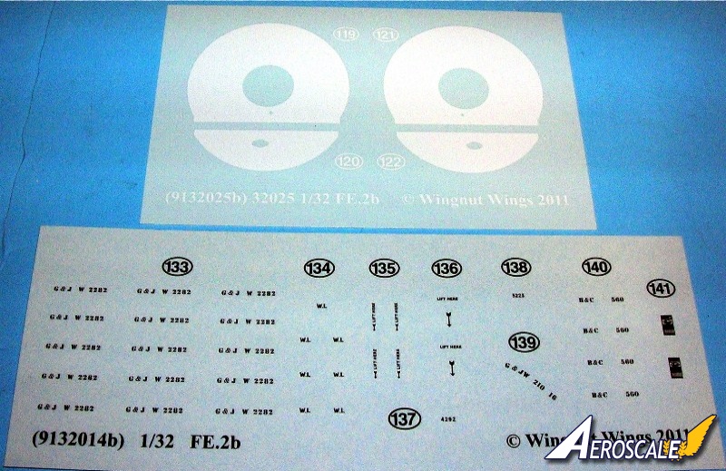
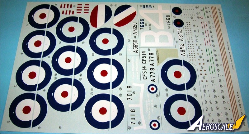
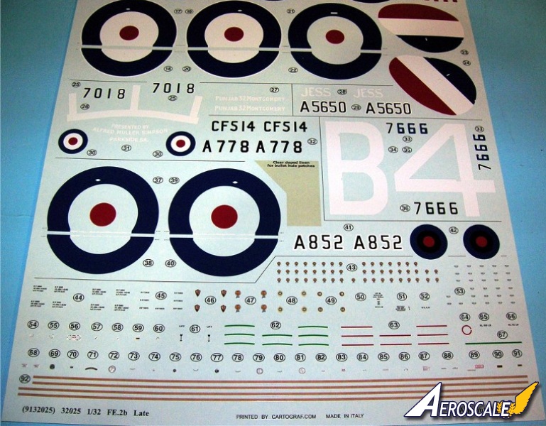
The decals are printed in good register on the samples. Three sheets are supplied, one large main sheet laying at the bottom of the box, with two small supplementary sheet containing some extra stencil marks and night operations cockades.
Each cockade is printed as one unit with the centers in place, and there's a choice of white or clear rings depending on the chosen scheme. The rudder stripes, with separate serial numbers for three of the five options. The blue of the roundels is a rich ultramarine.
A nice touch is the inclusion of lengths of decal for the bindings around the booms, and even a section of simulated "clear doped linen" decal to cut bullet-hole patches from.
References
1. Windsock Datafile #147 "RAF FE.2b At War" by Paul R Hare, Albatros Productions, 2011.
2. RAF FE2b Windsock Datafile, JM Bruce, 1989.
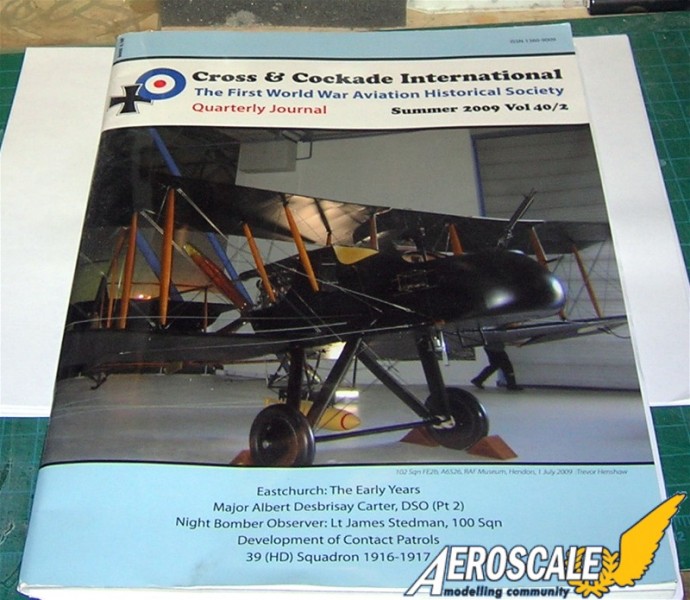
3. The Royal Aircraft Factory FE.2b/d & variants in RFC, RAF, RNAS & AFC Service, various authors, Cross & Cockade International, 2009.
I highly recommend that you follow the build log of Aeroscale member Mikael Terfors In the additional images topic below.
Please remember, when contacting retailers or manufacturers, to mention that you saw their products highlighted here - on AEROSCALE.
Highs: Construction is easy to follow if you are well vewrsed in the instructions. Highly detailed parts and instructions. Good decals.Lows: This is not a kit for beginners.Verdict: Wingnut Wings' FE.2b kit is another one of their best efforts.
Our Thanks to Wingnut Wings! This item was provided by them for the purpose of having it reviewed on this KitMaker Network site. If you would like your kit, book, or product reviewed, please contact us.
About Stephen T. Lawson (JackFlash) FROM: COLORADO, UNITED STATES
I was building Off topic jet age kits at the age of 7. I remember building my first WWI kit way back in 1964-5 at the age of 8-9. Hundreds of 1/72 scale Revell and Airfix kits later my eyes started to change and I wanted to do more detail. With the advent of DML / Dragon and Eduard I sold off my ...
Very nice review Stephen - Thanks for posting.
I totally agree with you that this is one of WNWs finest efforts to date. So far everything has fitted beautifully and been a joy to assemble.
Your point of pinning the lower wings, is a good call. Having dryfitted them into the finished nacelle, I can feel a bit of play, so to get the correct angle, pinning and perhaps using some sort of jig is a good idea.
I will also step out a bit of sequence in the assembly, waiting to attatch the landing gear until the lower wings are in place.
I'm also thinking about not assembling the upperwing, attaching the center section first to the cabanes and interplane struts, then sliding in the outer wings... The fit of these is very good, but we'll see how I get on. Hopefully this work thing will end soon so that I can get a bit of time building.
Best Regards
Mikael


Comments