Late in the air war high speed and diving ability became as equally important as maneuverability. In this case Pfalz was taking a page from the French Spad fighter series. The thin-low drag airfoil profile that made the Spad fast and hard to beat in a dive was just the ticket that the Pfalz design team was looking for. The typical top wing radiator soon gave way to the nose installed radiator. In early 1918 the eight individual interplane struts were replaced with four sets of "N" struts of the type seen on the up and coming Fokker D.VII. By the time that the Second Fighter Competition was begun (May 27 to June 21 1918) four D.XII types with various engines were available for engine performance tests. It is believed that the Mercedes D.IIIaü 180hp and possibly the D.IIIav 200hp were installed in various production Pfalz D.XII airframes.
Observations from Lt. R. Stark, JG IV commander:
"The sight of them does not inspire much confidence. The fuselage and controls are the usual kinds, the wings are somewhat more compact, with a multitude of bracing wires. The entire contrivance looks just like a harp. We are spoiled for such machines after becoming accustomed to the unbraced Fokker wings. The ground crews grumbled because of the trouble all that bracing was going to cause and cursed the extra work. Each of us climbed into the new fighters with prejudice and immediately began looking for as many faults as possible. No one wanted to fly these Pfalzs (sic), except under duress and made as much of a stink as they could about practicing with them. . ."
Later he again wrote;
. . .Our pilots got on very well with the Pfalz. They flew decently and could always keep pace with the Fokkers. In fact, they dived even faster, but they were ham-fisted and heavy in a turn. If the Fokker was a bloodstock racehorse, the Pfalz was a clumsy, but obedient cart animal. . .
From known production orders:
Feb.1918 200 airframes s/n D.1350 - 1549/18.
Apr.1918 400 airframes s/n D.2400 - 2799/18.
Apr.1918 150 airframes s/n D.2850 - 2999/18.
This totals 750 aircraft. In January 1918, Idflieg had committed the Pfalz Flugzeugwerke to 150 D Class aircraft per month commencing May 1918. At that rate the Pfalz Flugzeugwerke would have completed the above orders on 30 September 1918.
The following units were known to have received Pfalz D.XII, in whole or in part: Jasta 5, 17, 23b, 24s, 32b, 34b, 35b, 36, 37, 43, 61, 64w, 65, 66, 71, 73, 76b, 77b, 78b and 81. Of the 20 listed Jasta ,13 non-Bavarian units received the Pfalz D.XII, which illustrates it was not just for the Bavarian Jasta. It is also possible there were other Jastas that received the Pfalz D.XII to supplement the Fok. D.VII as well as the Rol. D.VIa and D.VIb in their inventory. In the second half of 1918, there were only a few Jasta that were equipped with a single type machine.
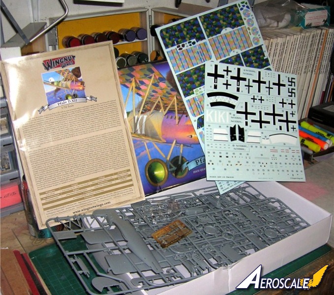
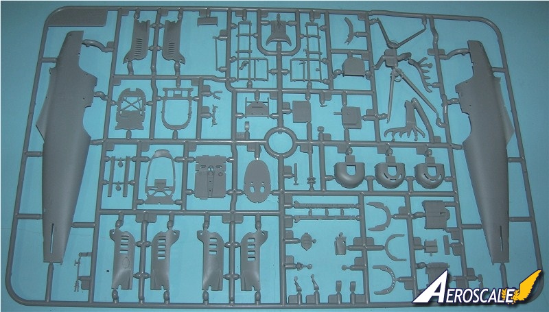
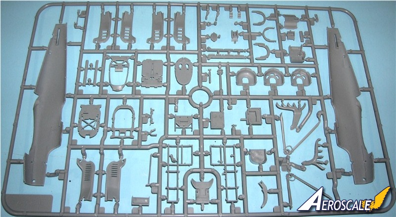
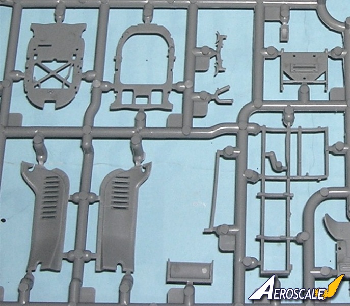
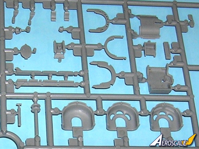
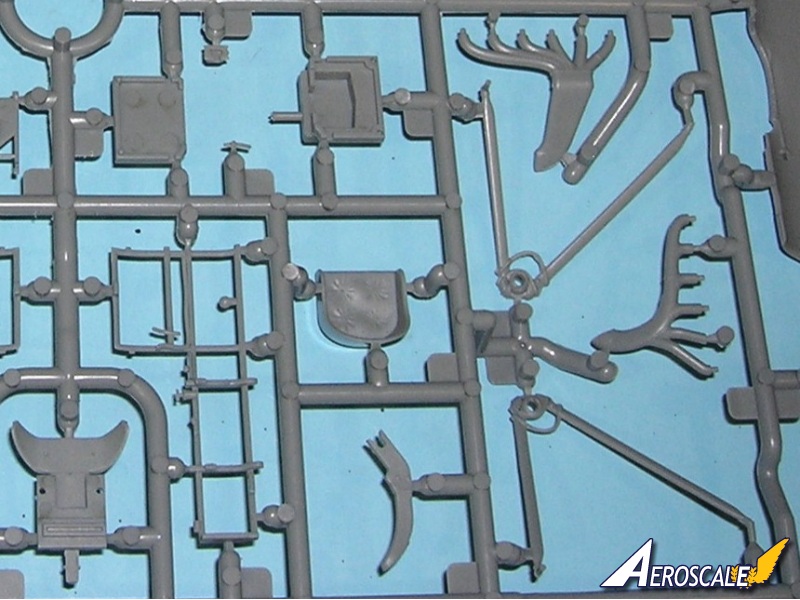
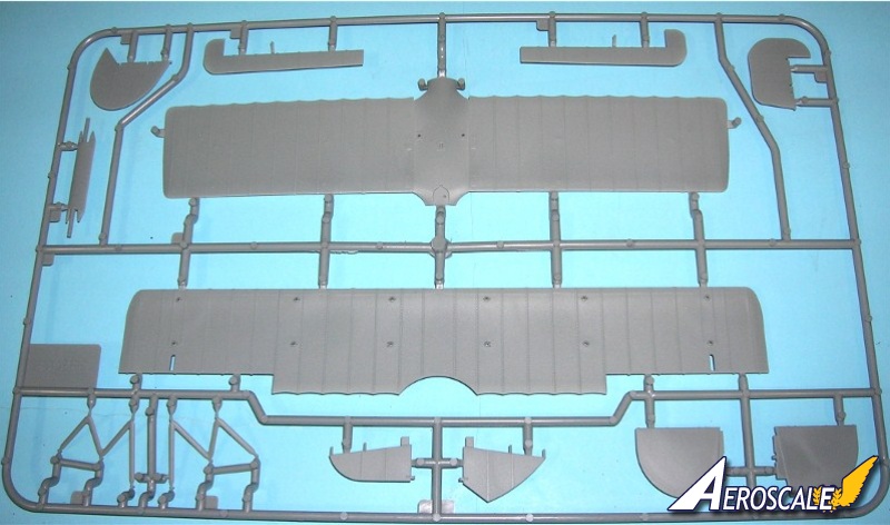
Kit Contents:
Plastic parts 144 pieces
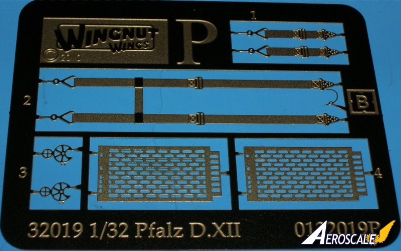
Photoetch 7 pieces
Lozenge for 1 aircraft cookie cutter type
Decal profiles 5 aircraft
Instructions 28 pages
I had the pleasure of receiving a preproduction kit that did not get sold at the Wellington 2011 Expo.
The Build:
Step 1. Cockpit. We start with the seat assembly (A 10 & 19). It is advisable that you add the PE lap and shoulder harness straps (P 1 & 2) at this time. See step 2 of the instructions. The fuselage formers (A 6, 8 & 27) make up the midsection of the cockpit. Add the fuel tank pressure hand pump (A 30). The auxiliary throttle advance lever, grease pump Bosch starting magneto are on the pilots left side fuselage former (A 8). The water pump greaser should have a feed- line leading forward in to the engine bay. Painted solder works just fine for this.
The Bosch starting magneto (A 22) should have a key that was attached by a small chain but would reach to the circular instrument face. It resembles a long handled key to the ignition of a modern car. Also it should have ignition wires with a faded red insulation cover leading from the lower area of along the fuselage interior toward the forward area of the engine compartment too. WNW did supply an auxiliary throttle advance lever in this kit and appears to be on A 8 as well. On the cockpit flooring / main fuel tank (A 28) add cables and a control column lock can be manufactured for the control column base (A 16). Note also that the rotating throttle with the circular collar on the control yoke head (A 35) should be on the pilot's left. The machine gun triggers are mounted to the column (A 16). Also add the rudder control bar (A 17). The aileron actuation bar is under the flooring (A 28) and has not been included separately in this kit. Use the kit fuel /air control panel (A 56) and mounted it per kit instructions. The attempt at scratch building scale wiring and a fuel control harness will be fragile but will pay greatly in the end. Add the rear cockpit screen (A 29).
Here is a list of other items that I would add to the cockpit.
a. 2 synchronizer cables from engine to gun breaches.
b. 2 Bowden cables from control column to the guns.
c. 2 rudder, 4 elevator cables.
d. brass or metal conduit pipes for the electrical wiring and fuel control harness from the instrument cluster (A 56) on the pilot's right.
Note! WNW has been listening to our concerns and now provides graphic arts in their instructions to plot the paths of the cables from the guns to the rear cockpit screen.
Step 2. Engine bay. Next we construct the fuselage structure for the engine compartment. The fuselage former (A 14) locks into the assembly from step 1. The exact placement of the engine bearer shelves (A 40 & 41) in the fuselage formers (A 14, 50, 51 & 52) is easy to deal with. They come together here as a subassembly. On the next page the interior painting guide also gives you decal gauge face locations.
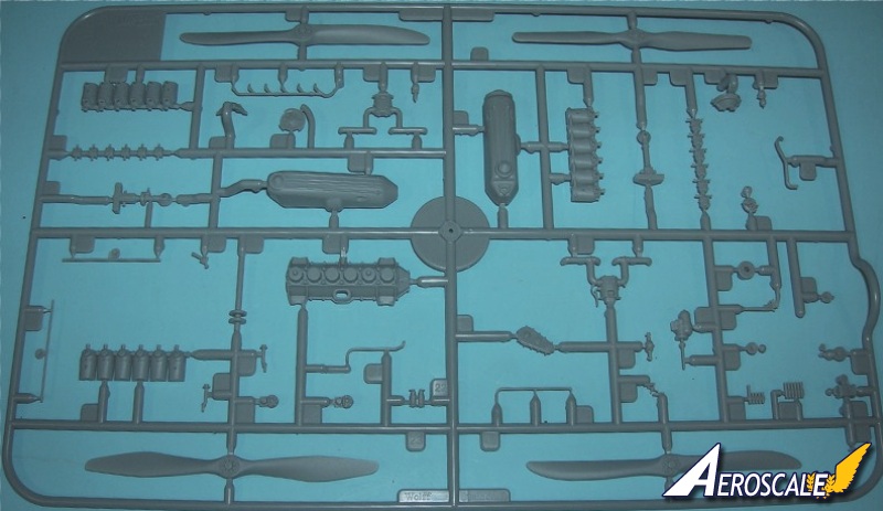
Step 3. Daimler Mercedes D.IIIaü 180hp (rated between 180hp - 200hp). On their 180hp Mercedes D. IIIaü six cylinder inline engine WNW uses ( A 12, 31, E 8, 11, 14-22, 25-27, 30-33, 36, 42 & 43). Daimler Mercedes D.IIIaü 180hp and were generally known by the company as F 1466a. The upper portions of the original aircraft engine cylinders are covered by water jackets these are the color of black/blued gun metal. The kit includes the oil filler tubes / vent caps (E 17 & 18), oil cycling tube (E 30) and the sparkplug wire conduit tubes (E 15 X 2) for both side views of the engine. The water feed line (E 42) to the jacketed intake manifold (E 33).
What you do not get in the kit is the water line tubes (sending and receiving) from the water pump to the radiator. And the oil sending tubes for the resevoir tank and upper & lower casing. This was located on the pilots right side of the engine midway and is to be flanked by two flanges. (See page 6 lower left corner image). But again you can add these from solder. Note the carburetor set up (E 22) and its orientation.
Note on these kit instructions the horizontal dual air pump is mislabeled as E 27 and should read E 37. The horizontal dual pump (E 37) came into use in March of 1918. Add fine wire painted black or white to make spark plug wires.
In 1918 the Mercedes D.IIIaü 180hp was the standard engine. Many, many Mercedes D. III and IIIa type motors were rebuilt to the D.IIIaü 180hp specifications at the airparks and the main rebuilding facility as the war progressed. That is why some captured examples had motors with the i.d. designation of D.III 160hp cast into their crankcases. This has caused the misconception that the standard 160hp and 170 hp were used in 1918 at a time when they had become obsolete. Often these were referred to as 160hp over compressed engines. On the Mercedes D. type motors the decompression lever (A 12) was at the top of the tower (E 26) and employed during engine maintenance & repair. The handle was wood and could be unscrewed. The crank cases that had the generator shelf were normally for wireless equipped machines. No Pfalz D.XII ever had a wireless yet the shelf as a standard option and appears to have been added regardless of airframe application.
Step 4. Install the completed engine at this time to the sub-assemblies from steps 1 & 2. The oil tank (A 53) will sit on the engine shelf (A 41) - see step 4. The ammunition, reserve fuel tank and empty belt collection box assembly (A 4, 20, & 23) sits on is the top of the main longerons. There is also an additional longeron (A 5) for the centerline belly area.
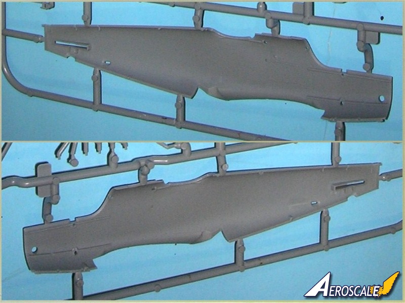
Step 5. Now we bring fuselage halves (A 1 & 12) together and pre drill all rigging holes. But first I would go further and scribe parallel lines on the inside the cockpit walls to represent the fabric strips. (WNW says paper and they could very well have used both at various times) These went into the make-up of the Pfalz fuselage shell halves. These covered the inner face of the wood lath joints. WNW provided these in their Pfalz D.IIIa (#32006) but not this kit. Photographic evidence shows that the fuselage formers and the interior of the fuselage shells were doped painted with the same covering as the outside surfaces. Then erase all union seams. I use gap filling super glue (semi gelatin) to fill joint seams between all plastic parts joined to the fuselage.
Step 6. Spandau Maxim 08/15 Machine Guns. The tachometer (decal 74 ) face on the cockpit coaming assembly (A 7, 45, 46 & 49) types appears to be upright in all cases. On other single seat types they were laid on their sides. Concerning the twin Spandau Maxim guns (D 9 X 2 or D 10 X 2), if you thinking about exposing the engine and adding photoetch gun jackets (P 3 X 2 & 4 X 2) add them here. Also, confirmed by photographic evidence that none of the Pfalz D.XII types had a spade shaped cocking handle during the war. These are popular items that some modelers like to add. The Pfalz fighters used T shaped handles ( but there should be two of these.) in the cockpit leading from the cocking levers on the right side of the gun breeches and worked via a linkage system. For further detail the left side of the upper cockpit area, add an auxiliary throttle push / pull rod. These items came as "L" shaped handles. See top left photo image page 4.
Step 7. The Teeves & Braun radiator (A 54, 55& 57) should be added after the engine is installed in the airframe assembly. It fits over the lower chin cowling (A 33). I note there are several chin pans provided in the kit (A 32-34). This tells us that later there will be future WNW decal sheets that will deal with these parts being included.
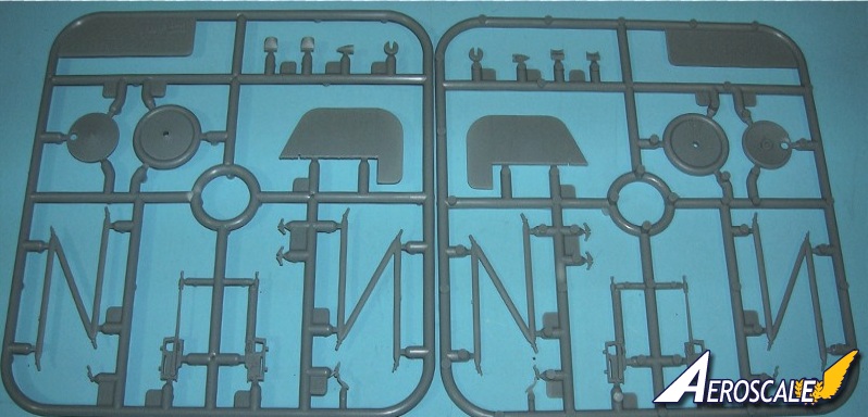
Step 8. Fuselage details. The horizontal tail unit (B 5 & 6) fit in place with locator tabs. The assemblies from steps 6 & 7 are added as well. The air scoop (D 4) goes on the pilots left near the radiator & upper cowl area. Check the photo images, specifically back on page 8. The horizontal stabilizers (B 5 & 6) were ply covered and painted.
Step 9 & 10. Fin & rudder applications. Add the rudder and fin for the profile you have chosen. These are for early production (B 3, 13 & D 11) or late production (B 4, 10 & D 11) types.
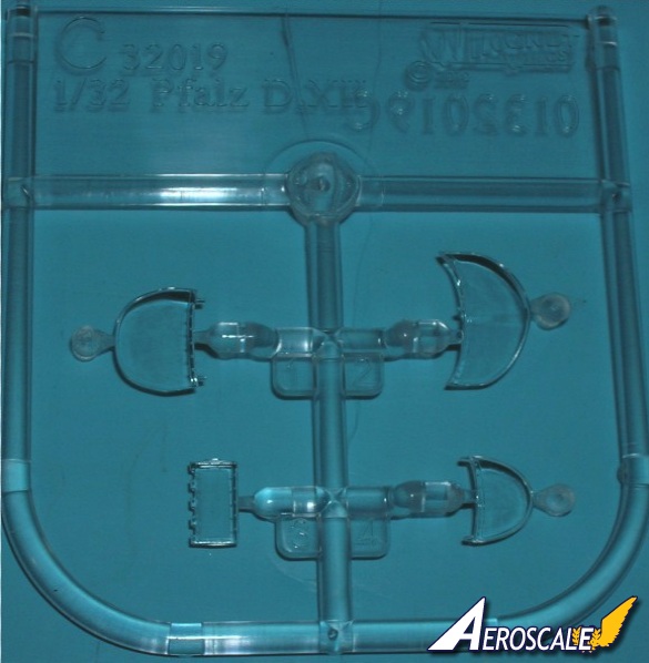
Step 11. More fuselage details. Note that canting control surfaces (D 6 X2) tends to give the piece a more natural look seen in period images of the real aircraft. These were fabric covered. The kit rigging control horns (D 9 X 2) can be used per the instructions. The outer ammo feed (A 47) and empty belt tube (A 44) and flash guards (A 26) are added next. The inner ammo (A 46) feed and empty belt tube (A 45) (between the guns) is not detailed in the build but simply shown in place. Do not add the windshield (C 1, 3 or 4) that fits the profile you have chosen yet. Due to its location C 3 will be problematic to attach later. To get a clear clean windscreen you may have to paint the framing and then add very low tack tape to both sides. It will have to be anchored securely and after an overall dull or flat coat at the end of the build - then pull the low tack tape off.
Step 12. Engine cowls (A 36, 37, 38 & 39) again follows the choice of the profiles you have chosen. There is a modification that covers D.1445/18 (and 1437/18 on page 24) See my comments on this profile. Because of the fuselages high cowling around the cylinders not much of this area will be seen later if they are permanently installed.
Step 13. Then you choose the type of exhaust set up for the profile you have chosen (A 13 or 24). You may want to make provisions about pinning this item to the engine. This entails drilling corresponding holes and adding brass rod to them so that when they are mated you have a rigid joint.
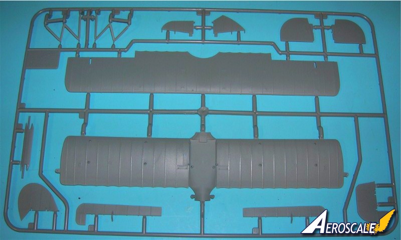
Step 14. Lower wings. Add the lower wing (B 9) at this time it looks like only minor sanding to finish. The fit looks near perfect. Note, cabane struts are (B 1 & 2) the instructions note 2 X B1 but that is incorrect. With all wing struts (B 1 & 2 or D 12 & 17 X 2) or rigging cable pilot ends enter the wing at an angle drill your insert holes accordingly. For the lower wing (B 9) I generally paint or apply lozenge to the upper surface (B 9) at this point before assembly and rigging. It is easier to clean up the unfinished area if you are drilling through the wing surface to anchor rigging.
Step 15. Upper Wing and ailerons. Top wing (B 7, 11 & 12) details show the angle of the struts from the nose view. The locations of national markings on some airframes varied slightly. Strut decal locations are noted as well. Now bring the fuselage and top wing together. For the top wing (B 7) I generally paint or apply lozenge to the undersurface of the top wing at this point before assembly and rigging. It is easier to clean up the unfinished area if you are drilling through the wing surface to anchor rigging.
Step 16. Undercarriage / Landing gear. The weakest part of a Vee strut landing gear assembly in plastic is the side to side twist. In many kits this usually causes the plastic gear legs to eventually dislocate or break. But with the WNW kit I would use the kit landing gear legs (A 11 & 25) and the exposed axle (B 8). Normally I use upholstery thread to wrap around the lower legs of the landing gear with the axle, to simulate the bungee shock chords. This looks like the original and actually secures the axle in place with one drop of cyanoacrylate glue. WNW provides this as molded detail on the landing gear lower ends. Finish any rigging now.
Most of the Pfalz fighters were equipped with the light and dark laminated propellers with a uniform tinted varnish overall. Carefully check the aircraft profile your modeling to choose the right propeller. WNW offers three possibilities with this kit. The company determined the paddle profile of the propeller (it was their trade mark) while the engine application determined its pitch and length, so all three profiles (E 24 - Axial, 35 - Heine & 46 - Neindorf) could be seen on the Pfalz D.XII. They all had the same pitch because of the factorys installation of the Mercedes D IIIaü 180hp motor. Lastly add the tail skid (A 9). Add the windshield (C 1 or 4) that fits the profile you have chosen yet. The discussion on how to attach C3 is back in step 11.
Step 17. Rigging diagram needs to be referenced repeatedly during the steps where you unite the wings to the fuselage.
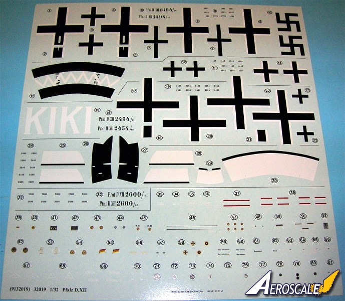
Kit Decals:
A. Pfalz D.DXII 1394/18 Jasta 77b July(?) 1918. I don't believe swastika is the correct term here. The vertical or 90 degree crosses were termed "Hakenkreuz". The other term did not come along until WWI when it was canted up on a 45 degree angle. As mentioned by WNW this insignia was used by many pilots on both sides for a reference to good luck.
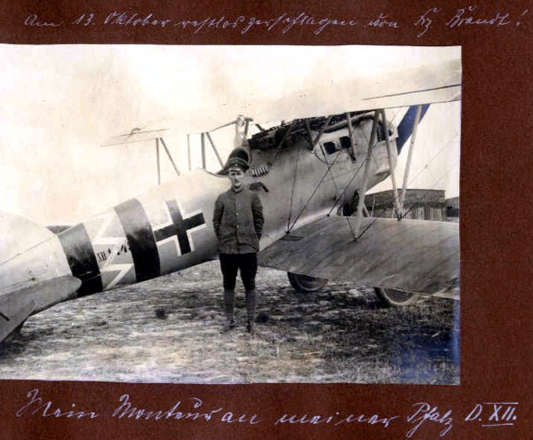
B. Pfalz D.DXII 1445/18 Jasta 49 (?) 1918. There is some controversy over the second image and the unit it was assigned to. I have seen the photo album this scheme came from Pfalz D.1445/18 of Kest (Home Defense Fighter Unit) 4b. This machine was piloted by a Gefr. (Private) Langenheim in late 1918. Now walk with me on this. I have seen the album that this image comes from. Held it in my hands and studied it. It is the property of Mr. Dubois - Tyson. The latter is his birth name. This album was originated by a Gefreiter (Private) Langenheim. He served in Jasta 28, Jasta 49 and Kest 4b. The following is from Rick Duiven's Jasta 49 roster.
'. . . Flg. Langenheim came (from Jasta 28?) on 17 Feb.1918 to Jasta
49. On 8 March 1918 he was IIC.but his condition worsened
and he went to the Hosp on or about 18(?) May 1918. He leaves the
Jasta 49 rolls in Sept. 1918 he was transferred to Kest 4b. . ."
The image of Pfalz D.XII 1445/18 is from his album. The captions state this ". . .13 October 1918 . . .my mechanic and my Pfalz D.XII." This date in his album shows the machine D.XII 1445/18 was from Kest 4b as is D.XII 1437/18 on the instructions page 24. It also is in the same photo album. He makes a vague reference to the horrors he saw at a forced labor camp.
C. Pfalz D.DXII 2454/18 KI Jasta 32b(?) 1918. WNW gives you two options on the overall camouflage scheme. This is based on info from contemporary sources.
D. Pfalz D.DXII 2486/18 Ltn Paul Vogel, Jasta 23b Sept. 1918. While WNW has given a good account of this machine in their instructions I will expand on this with info from the Late Peter Grosz and my personal studies;
. . .After the first war, 2 Pfalz D.XII were sent to the USA in crates marked as Fokker D.VII types. One was discovered to be D. 2486/18 a former Jasta 23b machine. . . After the mislabeling was discovered both machines were sold by the U.S. Dept of Commerce and they both passed through various private owners. The history of 2486/18 shows it was purchased by Buck Kennell and he is photographed with it in 1938. By then helpfully restored by Col. Jarrett (He was the owner of the other Pfalz type in the USA, D.XII 2848/18). D.2486/18 had acquired similar dark and white bands seen on Jasta 32b machines. At this time instead of Orthochromatic film Panchromatic film was more popularly in use. The bands look black and white to me in the photos I have seen. During its service with Jasta 23b 2486/18 employed the unit's broad black and white bands around the tail plane. Greg Van Wyngarden covered their markings well in the old Cross & Cockade USA Volume 21 #3 Autumn 1980.
E. Pfalz D.DXII 2600/18 Late 1918. Most of this machines known history comes after it was captured and sent to Australia to be ultimately placed in their War Memorial Museum. It has gone through several touch ups, repairs and at least one full restoration previously. WNW even recommendations for covering the machine in a camouflage matching the 2008 restoration.
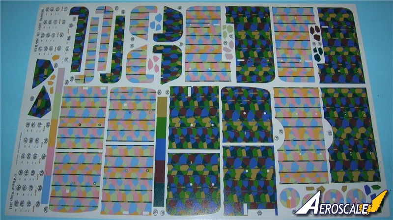
Lozenge:
Much has been written on the fine quality of the WNW German lozenge decal colours. Though they are a bit intense they are easy too work with and with some "texturing" can be very convincing. These are "Cookie Cutter" or fitted types and just fit this kit. The rib tapes are protrayed in place. But I would suggest purchasing their separate sheets to help out if the modeler themself messes it up. And also the kit doe not supply trailing edge tapes for the wings for either upper or lower surface.
References:
1. Cross & Cockade USA, Various issues.
2. German Aircraft of the First World War by Peter Gray and Owen Thetford. London: Putnam, 1962.
3. German Army Air Service in WWI by R. Rimell, Osprey Vintage Warbirds #2, 1985.
4. German Fighter Units June 1917 -1918 by A. Imrie, Osprey, Airwar #17, 1978.
5. Lafayette Foundation Archive (VAFM.org), Denver CO. USA
6. Pfalz Aircraft of World War I by Jack Herris, (Great War Aircraft in Profile, Volume 4). Boulder, Colorado: Flying Machine / Paladin Press, 2001.
7. Pfalz by P. Grosz & E. Krüger, WWI Aero Pub. inc. 1964.
8. Pfalz D.XII by P. Grosz, Datafile 41 Windsock, Albatros Pub. Ltd., 1993.
9. Pfalz D.XII, "A workhorse in foreign fields" by S. T. Lawson, C&C Intl. Vol. 30, #4, 1999.
10. Pfalz Scout Aces of World War I by Greg VanWyngarden, (Aircraft of the Aces No. 71). Oxford, UK: Osprey Publishing, 2006.
11. Pictorial History of the German Army Air Service by A. Imrie, Ian Allen Pub. 1971.
12. Scale Model Aircraft in Plastic Card by H. Woodman, Model & Allied Pub., 1975.
13. Scratchbuilding Techniques by Alan Clark, Scale Models Int. Pp174-5, 1990.
14. Spandau Machine Gun by David Watts, WWI Aero, 1998.
15. The Motion Picture Stunt Pilots and Hollywood's Classic Aviation Movies by Wynne, H. Hugh. Missoula, Montana: Pictorial Histories Publishing Company, 1987.
When contacting manufacturers and publishers please mention you saw this review at AEROSCALE
Highs: The standard of the kit is at the usual WNW fine efforts. The detail level is high as far as this reviewer can see. Lows: Minor typos in the instructions. Missing oil & water plumbing if the motor is to be displayed - cowlings off. No internal fuselage side wall detail. Verdict: This model kit is a fine effort and lacks very little in the way of needed improvements.
Our Thanks to Wingnut Wings! This item was provided by them for the purpose of having it reviewed on this KitMaker Network site. If you would like your kit, book, or product reviewed, please contact us.
About Stephen T. Lawson (JackFlash) FROM: COLORADO, UNITED STATES
I was building Off topic jet age kits at the age of 7. I remember building my first WWI kit way back in 1964-5 at the age of 8-9. Hundreds of 1/72 scale Revell and Airfix kits later my eyes started to change and I wanted to do more detail. With the advent of DML / Dragon and Eduard I sold off my ...
Greetings sir,
First thank you for your concern I will try to answer with your questions. First I will go back to my article Reference #9 in the review you mention.
Pfalz D.XII, "A workhorse in foreign fields" by S. T. Lawson, C&C Intl. Vol. 30, #4, 1999.
I too referenced the Datafile #41. I also knew Pete Grosz and had a phone conversations with him. First it is Pete's research I referenced. He was keen on studying serial numbers and technical details of WWI aircraft. Colours were something he cared little for. Originally the two Pfalz aircraft came from the British capture stores labeled as previously mentioned as "Fokker D.VII" types. As you also mention D.2486/18 was originally in a pretty demolished state. Even so it was used in a British "Ministry of Munitions report" for technical observations.
Both were in flying condition in 1929 and used in the movies but were often just set dressing in the films. D.2486/18 was altered into a 2 seater version with second cockpit opening in the spine. The photos I have from this time (from Pete Grosz) show the fuselage was not in its original factory shape and profile.
The two main owners of these machine after the US govt sold them into private ownership was a Col. Jarrett (who had an aircraft display (farm / museum) in New Jersey. The details are in my article. The person who took to thouroughly restoring D. 2486/18 was a Paramount props manager Buck Kennell. With Jarrett's help it was restored to a single seat aircraft and the fuselage was very close to the original shape.
The numbers thought to be serials 7511 & 7517 were factory werke serials and only one belonged to the Pfalz machines. Jarrett's machine 2848/17 was original 7511. So much of D.2486/18 was restored that most of its record was lost. Jarrett helped Buck Kennell restore his machine so a bogus serial number was applied.
Pete was given a "Fellowship" to the NASM and used this as a tool to further his research. It was he that came up with the original serial from the pertinent documents. This serial first appeared as as a note in Datafile #41 (published 1993) on survivor aircraft. My article was written in 1998 and published in 1999. No questions were posed on this serial then.
Since that time others have seriously questioned the idea. I can't see a whole serial as a typo. Transposed numbers are possible but Pete had the final say on the draft copy of the Datafile in question. Can anyone point out where Pete recanted this? I am not "all knowing" and would be interested in any verifiable info.
Yes, Buck Kennell's (D.2486/18) 7517 was handed over to the EAA in Wisconsin and after nearly seven years was badly handled. They put 1/8" of fibreglass over the whole fuselage. Much of the re-aquired instrumentation was missing. Hence the reason that NASM painted in similar livery as to when it was in is Hollywood heyday. Though I am sure it was black and white not red & white. They also chose to hang it from the ceiling as the cockpit is pretty bare. A any rate we have Peter M. Grosz as the author of the serial number research. By the way, Pete's research & historical documents all went to the German National Museum / Archive at the time of his death.
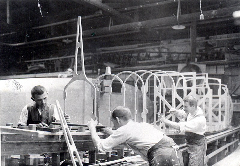
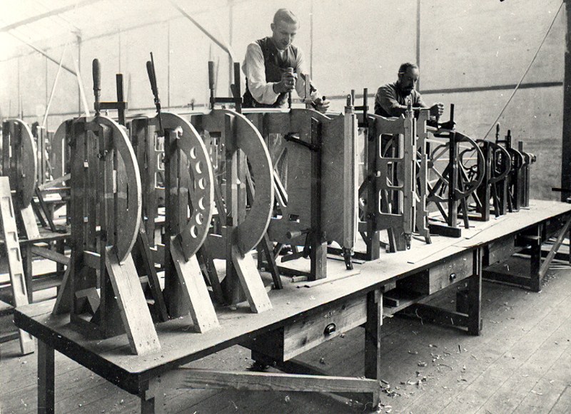
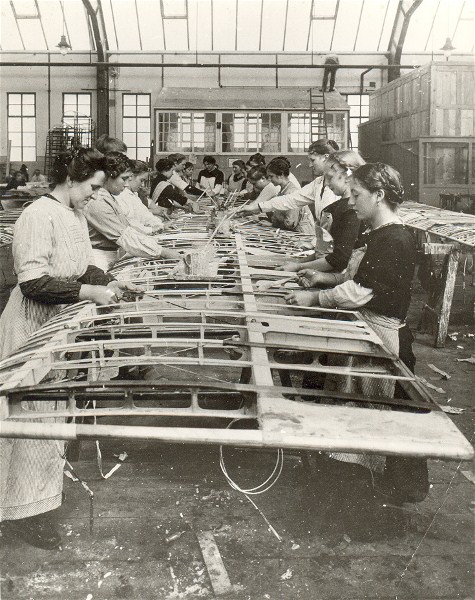
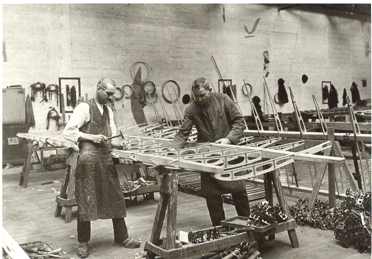
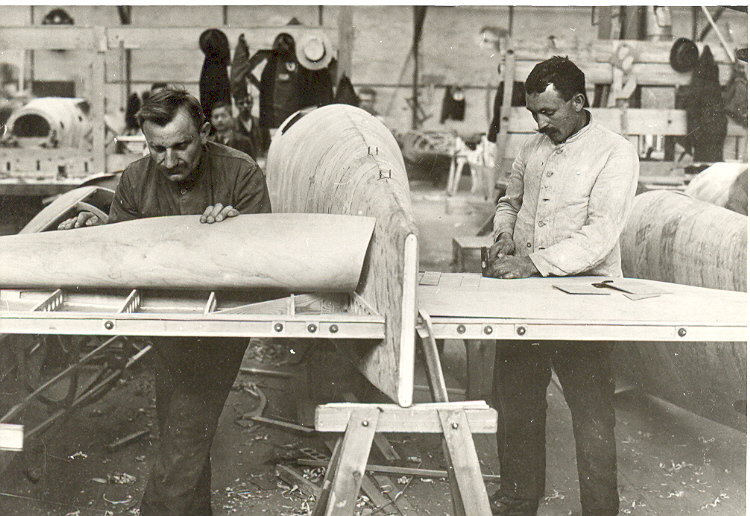
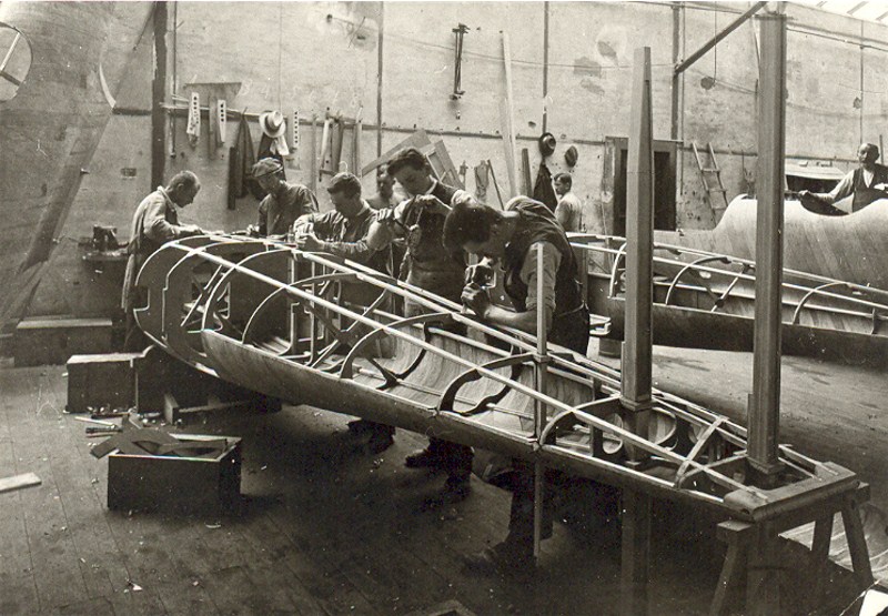
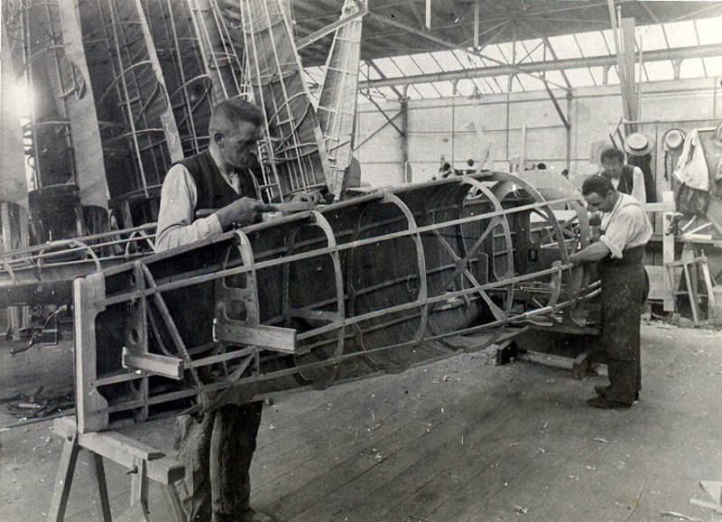
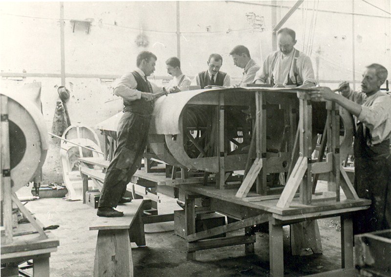
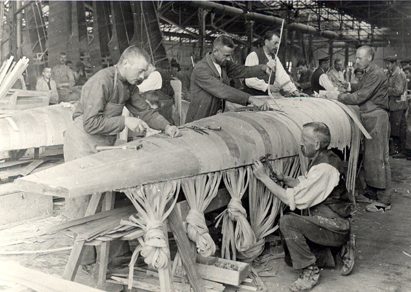
By the way I had a comment / request on the lath wood fuselage. Mostly the factory images I posted can answer your questions but here is a bit more.
"As a method of building up the fuselage, several manufacturers began by steaming wood over male molds. Think of it as vacuforming plastic over a male mold. Albatros did whole panel sections in 2-3mm plywood. Pfalz used strips of wood 1 - 2mm thick. They would steam the wood. and lay it down over the mold diagonally, then they would run another course diagonally on the opposite direction and apply glue to laminate these layer together. The resultant half shells were nailed and screwed to wooden formers and usually very durable. . ."


Comments