Background.
The DH Vampire was modified under Specification 45/46P and 46/46P so that it could be accepted into naval service. After trials with the prototype Vampires, LZ551/G [read the CMR Sae Vampire Prototype review
here,.] the Admiralty decided to order the Sea Vampire F.20 in 1947 for the Fleet Air Arm [FAA]. The first batch of Vampires FB.Mk.5's were built at Preston and flown down to Hatfield to be modified into the F.20 specification, which included modified wings, air brakes, main undercarriage and the fitting of a arrestor hook to stop the aircraft when landing on a carrier deck.
After a lengthy development programme, including numerous carrier landings, a more powerful Goblin engine was fitted. The first unit to fly the Sea Vampire was 702 Sqn FAA, who formed the Naval Jet Evaluation & Training Unit in April 1949 [remember that the jet aircraft were still a relatively new phenomenon], carrying out such development tasks as making carrier landing at night without lights! The Sea Vampire equipped at least 7 FAA squadrons before being replaced by the Sea Venom in 1955.
Source: Chris Hughes.
The Kit.
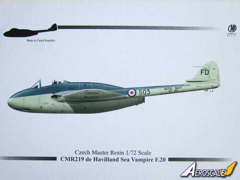
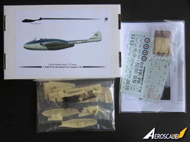
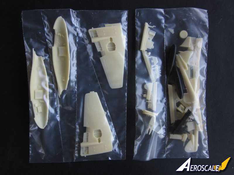
Very sturdy box with reinforced ends. There is an excellent illustration on the box cover of VV150, definitely worth keeping. All resin parts are placed in multi cell plastic bags. Canopies, masks, decals and photo etched [PE] parts are sealed separately.
Contents
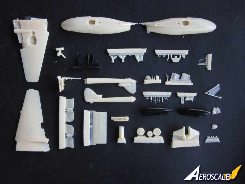
Approx 57 resin parts including two resin wing fuel tanks.
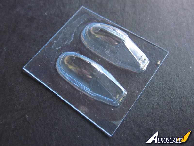
-2 x vac formed canopies moulded, canopies are in the closed position.
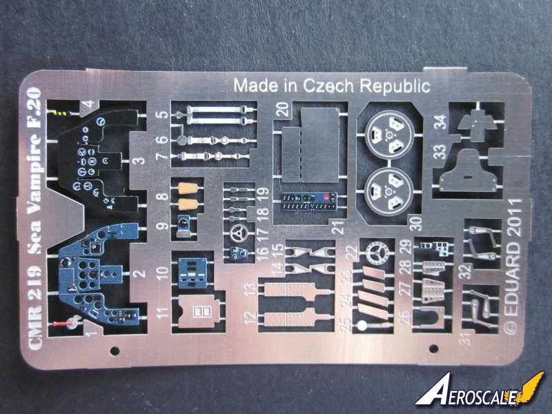
-1 x pre painted PE sheet created by Eduard.
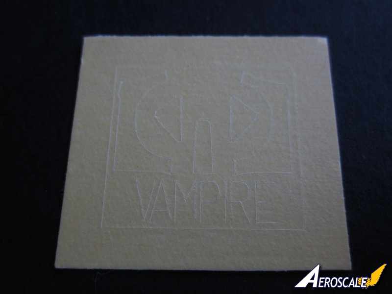
-1 x set of paint masks for the canopy, created by Eduard.
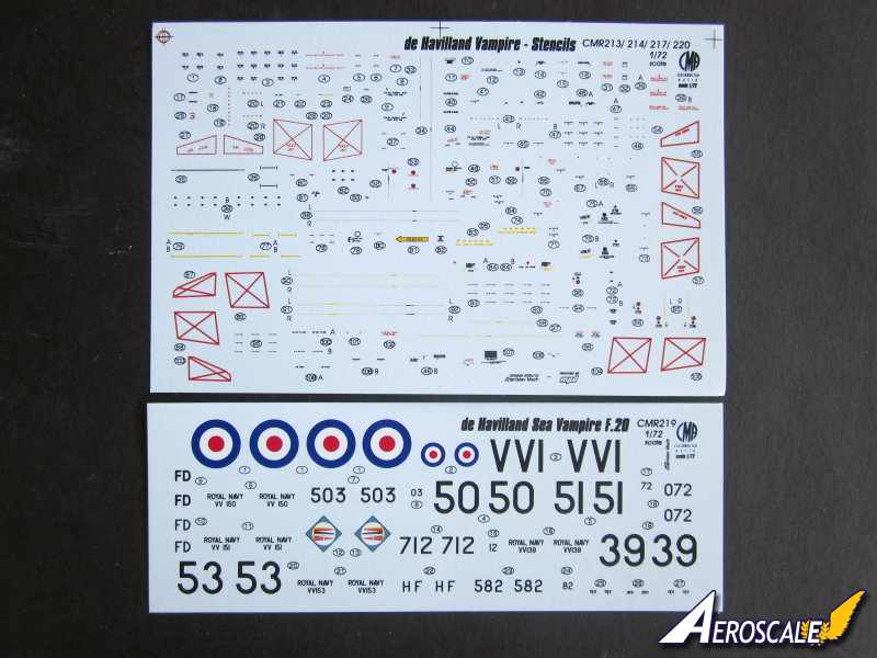
-2 x decal sheet.
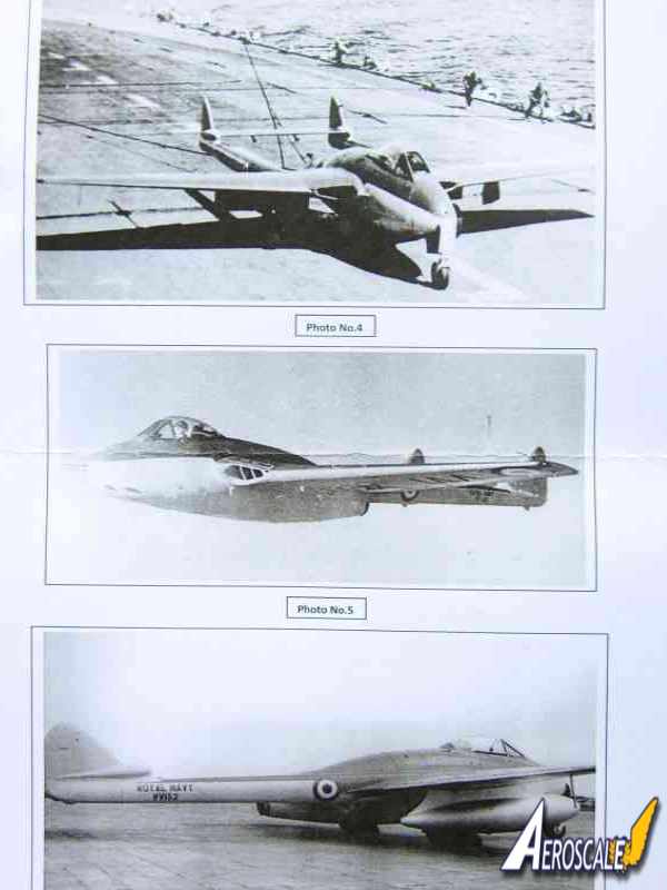
-3 x A4 pages of photo references, there are 8 black and white images.
-2 x A4 Pages of captions for the images, providing valuable information.
-6 x A4 pages construction guide including parts map.
-4 x A4 page of painting instructions.
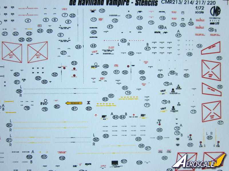
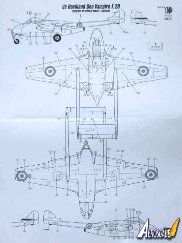
-1 x A4 page stencil guide.
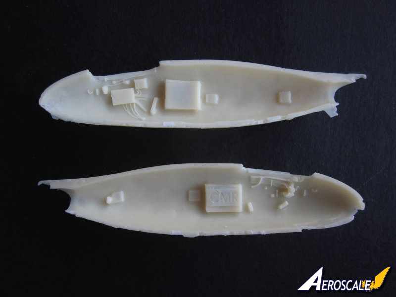
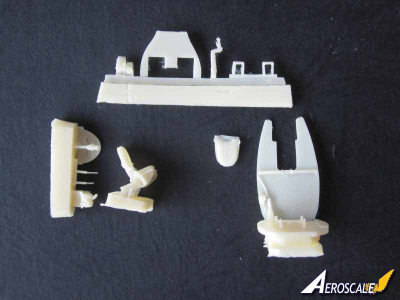
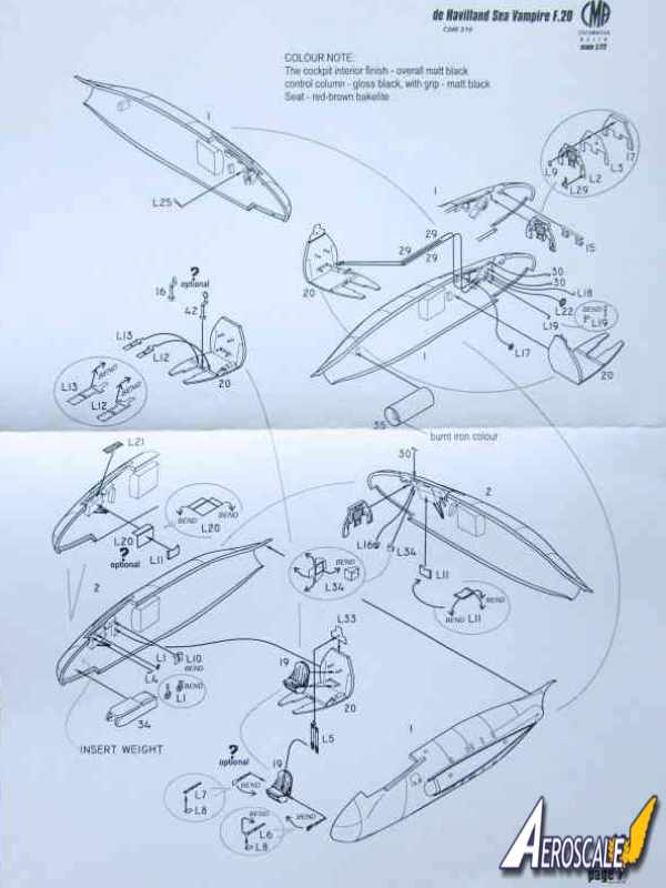
Cockpit: there are some very fine cast details, such as boxes and cabling on the inside of both fuselages where the cockpit is situated. The cockpit area is further enhanced with around ten resin and numerous pre coloured PE parts. Some of the parts are tiny and very delicate and will be very challenging to apply. The pre coloured instrument panel is a particularly fine representation of the real thing. The instrument panel is built up from three parts: the instrument fascia, the instrument faces and a resin back plate. The rest of the resin parts that make up the cockpit include a one piece rear bulkhead and floor, an excellent pilots seat to which you apply pre coloured PE harnesses. There are two choices of control column, stick or spade type. Also worth noting amongst the pre coloured PE parts are fuse boxes [they need to be folded], trim wheels and foot rests. The resin gun sight will need the two glass plates fitted to be scratch built. These could easily be created from the waste material from the canopies. The interior is mainly black in colour, the Bakelite seat and the addition of the PE parts will add some colour.
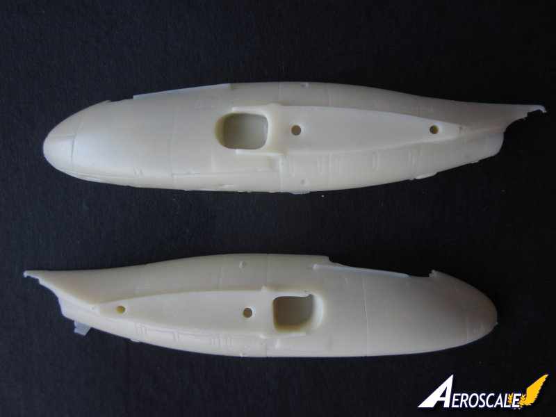
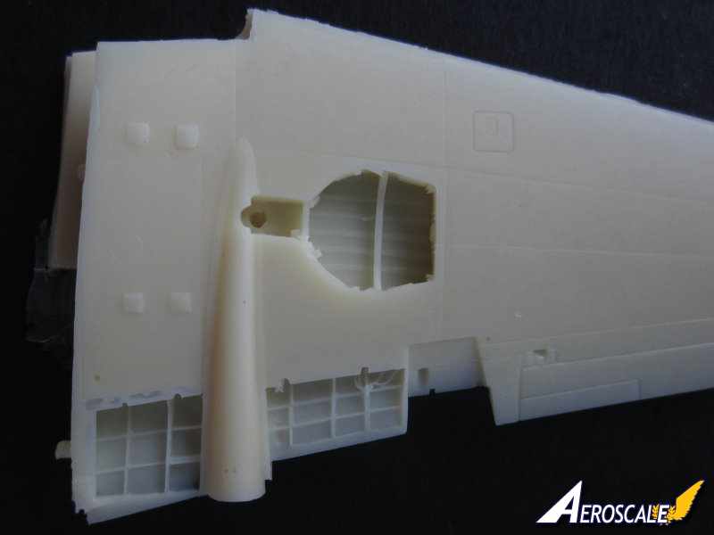
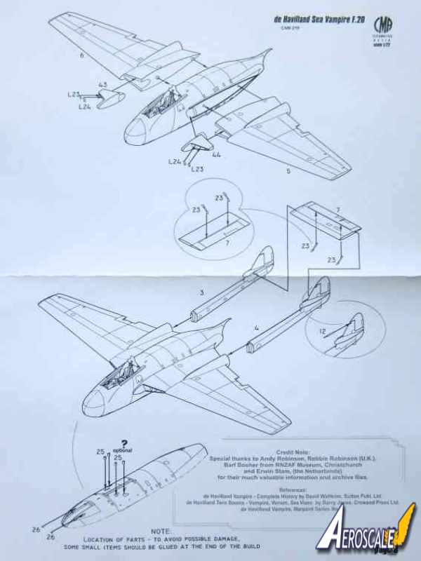
Fuselage: is split vertically. The cut outs for the front undercarriage well will need the very thin layer of flash removing before installing the one piece undercarriage well. The front undercarriage well does not have a lot of detail just like the real thing. The recesses for the cannon troughs and the spent cartridge chutes are nicely done. There are two small sections of resin cannon barrels to insert into the lower two troughs. There is also the option of fitting extended spent cartridge chutes to the underside of the fuselage. The area where the wings locate has four holes for the four locating pegs in the wings. There is a hole in each fuselage halve where the air ducts for the engine are located. The mating surfaces of the fuselage particularly the lower edges will need a few swipes with a sanding stick to clean up the edges. The exhaust pipe for the Goblin 2 engine needs to be fitted before the fuselage halves are glued. The shape of the fairing above the jet pipe is nicely captured as well as the shape of the nose. Panel, fasteners and rivet detail are finely recessed as are the canopy rails. The overall shape of the fuselage looks superb. A look over both fuselage halves revealed a few tiny air bubbles that should be very easy to fill using correction fluid or filler.
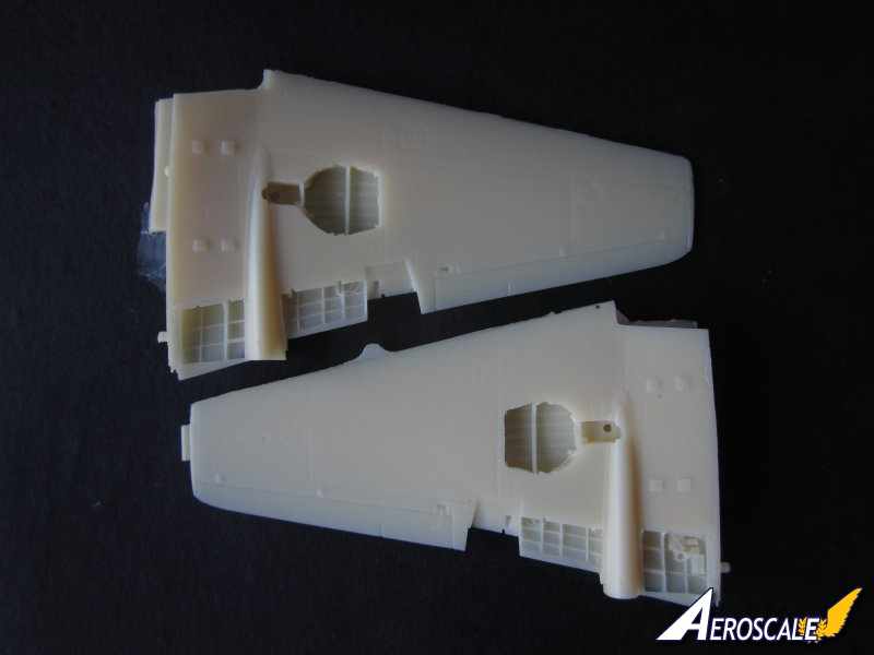
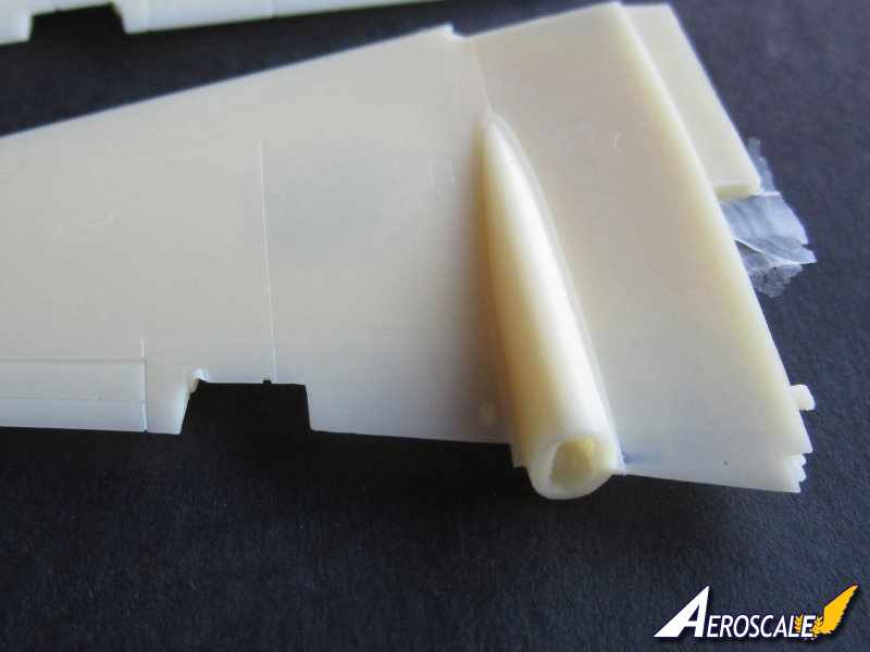
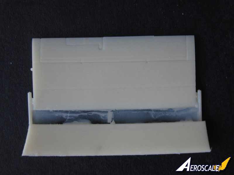
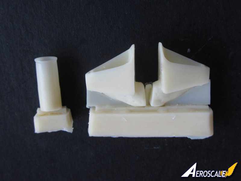
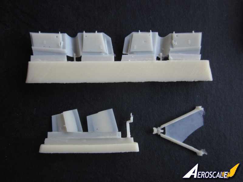
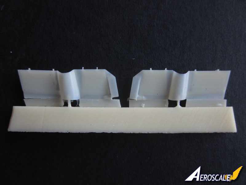
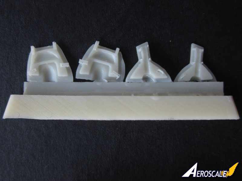
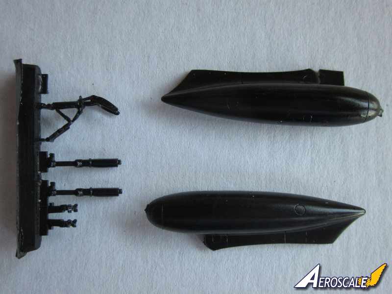
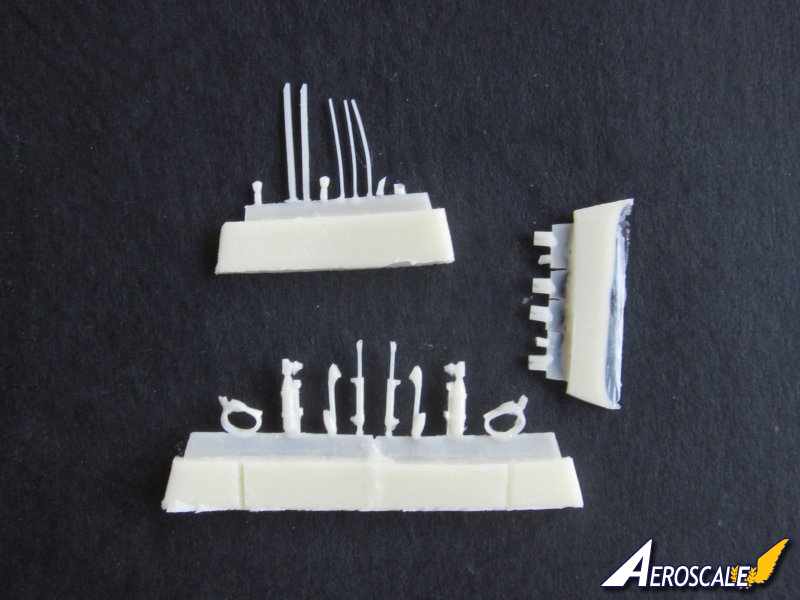
Wings: the two one piece wings have very positive pegs to fit into the fuselage wing roots. A test dry fit of the wings to the fuselage reveals an excellent fit. The two air intakes for the engines are cast separately, which offers the advantage of more accurate depth to the intakes. This approach to creating a more realistic looking air intakes does mean that some care will be needed to ensure a good fit with minimum amount of blending into the wing, but I think it's worth it. There are two vanes to glue into each of the intakes. The main wheel and the flap interior wells are beautifully detailed with low relief frame work and actuating mechanisms. The joint for the tail booms is on the trailing edges of the wings. The flaps and the airbrakes can be displayed open or closed. The two part flaps are extremely thin and will need some care separating them from their blocks. If you decide to display your Sea Vampire with flaps down then there are four tiny PE flap actuators arms and a number of resin parts to fit in place and two resin actuators arms on the airbrakes. As with the fuselage the panel lines are beautifully done, crisp and recessed. There are two 100 gallon fuel tanks that can be fitted to the wings if you wish. In my sample they are cast in black resin.
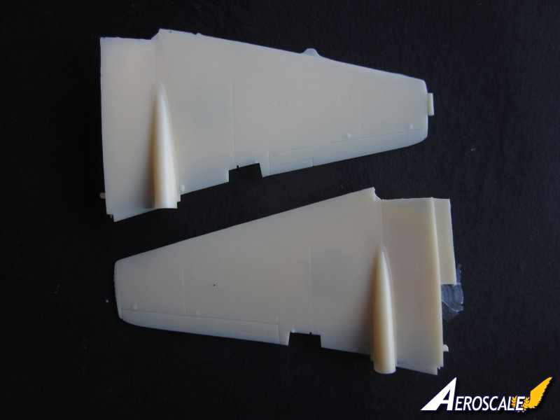
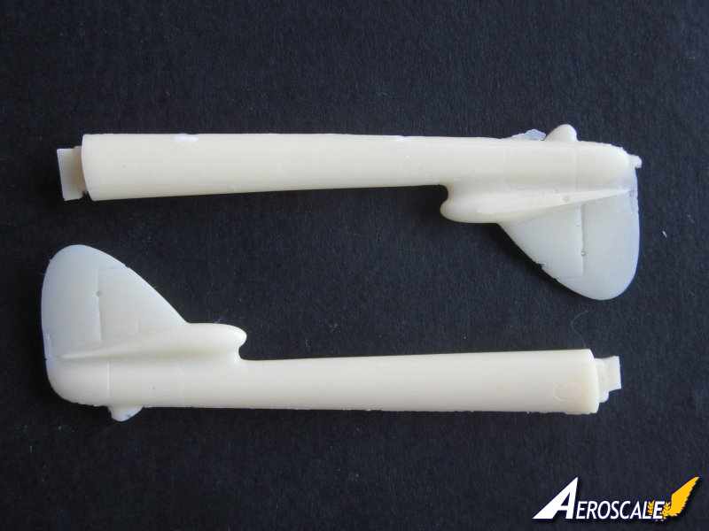
Tail booms and tail: Each boom is cast in one piece and includes the fin and rudder. The rudders have incredibly thin trailing. There is a stub that provides good support for the attachment of the boom to the wings. There is a small piece to detach to detach from the stub on the boom before joining. A dry test fit of the wing to the boom showed that there was an excellent fit. A whip aerial needs to be scratch built from 0.3mm wire and fitted to the port wing, the instructions supply exact measurements for it's location. In the instructions the length of the wire is indicated as 1 mm, but I suspect it should be nearer 10 mm. The one piece tail wing, which locates low down on the tail fin has four small pegs that fit into four small holes in the bullet fairings on the tail fins. The tail wing needs separating from it's block, but the contact area between the two is very thin, so the tail wing should separate easily enough. Again the trailing edges are realistically thin. There are two resin mass balances to be added to the under surface of the tail wing.
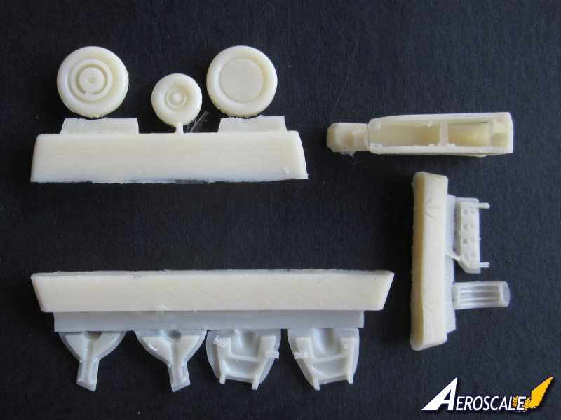
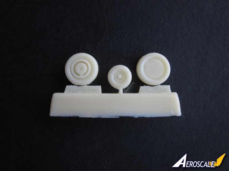
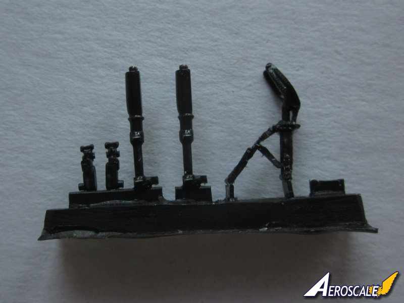
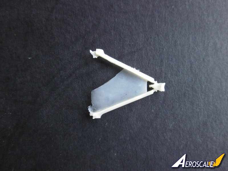
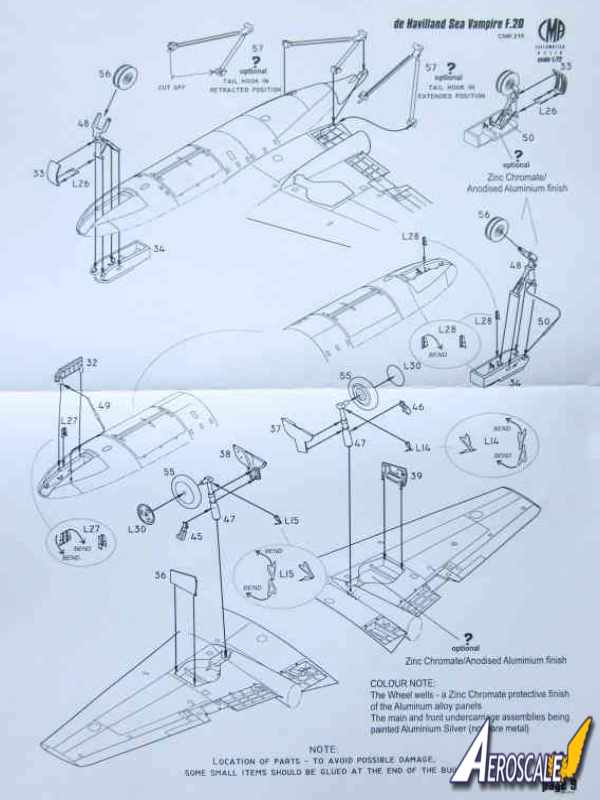
Undercarriage and tail hook: the undercarriage legs are cast in black resin and are possibly stronger than the resin used in the rest of the kit. The detail is very good, the front undercarriage unit is cast in one piece including the actuator arm, there is a little thin flash to remove. The wheels are rather nicely done, the distinctive twin raised tread of the front wheel is faithfully reproduced. There are PE spoked hubs to apply to the wheels as well as PE torsion links to the legs. The resin undercarriage doors have wonderful low relief detail cast on them. The arrestor hook can be displayed retracted or extended. If you decide to display the arrestor hook up the extended resin parts of the arrestor arms need to be cut off. The extended parts provide a positive fit into the fuselage if you display the tail hook down. There is a very thin layer of flash to remove before fitting.
Canopy and windscreen: the complete canopy and windscreen are vac formed in one piece. And the lovely folk at CMR provide two sets of clear parts. The framework on the windscreen looks good and I like the slightly blown appearance of the canopy. CMR provide paint masks for the clear parts, these are made by Eduard.
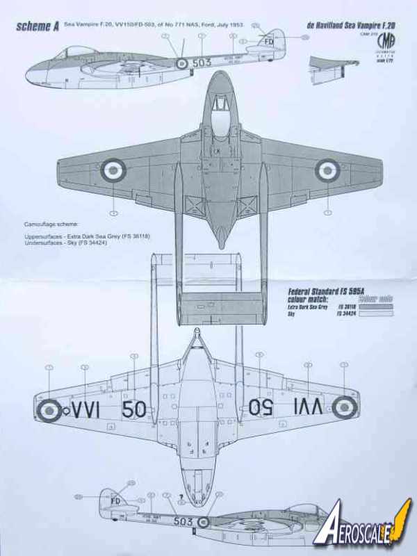
Markings: four schemes are provided by CMR:
-VV150, FD-503, No 771 Naval Air Squadron, RNAS Ford, July 1953.
-VV139, 072, No 703 Naval Air Squadron, RNAS Ford, 1953.
-VV153, HF-582, No 764 Naval Air Squadron, Hal Far, Malta, 1954.
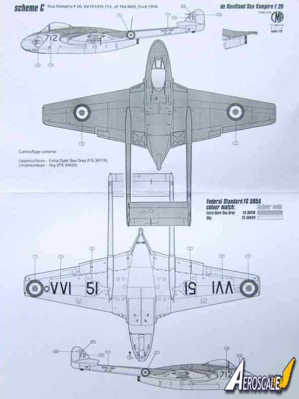
-VV151, FD-712, No 764 Naval Air Squadron, RNAS Ford, 1956.
Upper colours are extra dark sea grey [FS 36118] and lower surfaces are sky [FS 34424].
Decals: Decals have very good colour depth a registration, glossy and thin. There are quite a few stencils to apply. VV151 has a very interesting badge to apply on both sides of the nose comprising of three signal flags on a white background. Maybe a naval expert out there can interpret the message from the pennants, it would be nice to know.
Photographic references: there are eight images altogether from Tony O'Toole, each image is accompanied with some very informative captions. Images show the F.20 on deck, in flight and on the ground. Particularly interesting is the image of a F.20 being lowered on the lift of HMS Centaur. It would make an excellent diorama, especially with the deck crew crowded around it and the extreme weather evident in the image. Also what is apparent from the images is how clean these aircraft were in service.
Instructions: the six pages of instructions includes some very fine exploded line drawings as well as a parts key with all the components numbered. There are very useful colour notes for the various internal parts such as the cockpit, wheel and flap wells. There are also clear instructions of what to do with the PE parts as some require some bending. There is a very helpful guide for applying the paint masks to the windscreen and canopy. The paint guide has port and starboard profiles as well as upper and lower plan views. Each scheme is on a A4 sheet with details of the positioning of roundels, serial numbers, and the large squadron codes under the wings.
Conclusions.
I don't know if there are many Sea Vampires out there represented in 1/72 scale, but I have to say that CMR produce by far the best looking Vampires I have seen in 1/72. Accurate in outline, the kit will reward the modeler, with an outstanding model well worth the price. Incidentally there are images of the completed model on the CMR website
here. I have no hesitation in highly recommending this kit. If you choose to buy one you wont be disappointed. Nice one CMR.


Comments