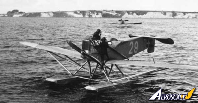
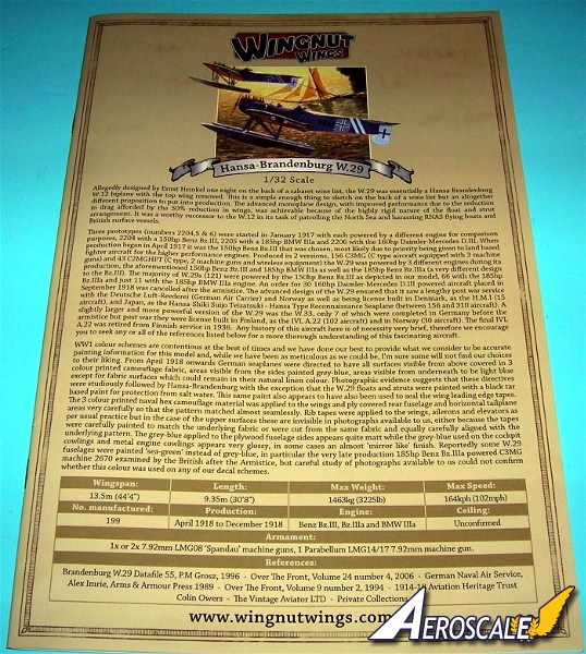
"Allegedly designed by Ernst Heinkel one night on the back of a cabaret wine list, the Hansa-Brandenburg W.29 was essentially an earlier Hansa-Brandenburg biplane W.12 design with the top wing removed. This is a simple enough thing to sketch on the back of a wine list but an altogether different proposition to put into production. The advanced monoplane design, with improved performance due to the reduction in drag afforded by the 50% reduction in wings, was achievable because of the highly rigid nature of the float and strut arrangement. It was a worthy successor to the W.12 in its task of patrolling the North Sea and harassing RNAS flying boats and British surface vessels.
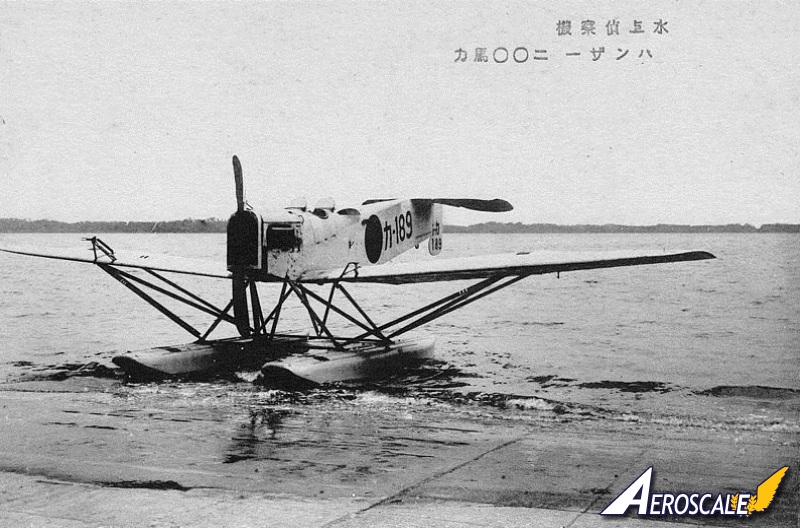
Three prototypes (numbers 2204,5 & 6) were started in January 1918 with each powered by a different engine for comparison purposes, 2204 with a 150hp Benz Bz.III, 2205 with a 185hp BMW IIIa and 2206 with the 160hp Daimler-Mercedes D.III. When production began in April 1918 it was the 150hp Benz Bz.III that was chosen, most likely due to priority being given to land based fighter aircraft for the higher performance engines. Produced in 2 versions, 156 C3MG (aircraft equipped with 3 machine guns) and 43 C2MGHFT (C type, 2 machine guns and wireless equipment) the W.29 was powered by 3 different engines during its production, the aforementioned 150hp Benz Bz.III and 185hp BMW IIIa as well as the 185hp Benz Bz.IIIa (a very different design to the Bz.III). The majority of W.29s (121) were powered by the 150hp Benz Bz.III as depicted in our kitset, 66 with 185hp Bz.IIIa and just 11 with the 185hp BMW IIIa engine. An order for 30 160hp Daimler-Mercedes D.III powered aircraft placed in September 1918 was cancelled after the armistice. The advanced design of the W.29 ensured that it saw a lengthy post war service with the Deutsche Luft-Reederei (German Air Carrier) and Norway as well as being license built in Denmark, as the H.M.I (15 aircraft), and Japan, as the Hansa-Shiki Suijo Teisatsuki - Hansa Type Reconnaissance Seaplane (between 156 and 310 aircraft). A slightly larger and more powerful version of the W.29 was the W.33, only 7 of which were completed in Germany before the armistice but post war they were license built in Finland, as the IVL A.22 (102 aircraft) and in Norway (30 aircraft). The final IVL A.22 was retired from Finnish service in 1936. Any history of this aircraft here is of necessity very brief, therefore we encourage you to seek any or all of the references listed below for a more thorough understanding of this fascinating aircraft." (from WNW website)
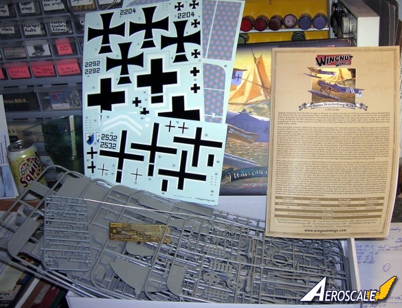
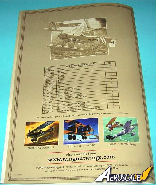
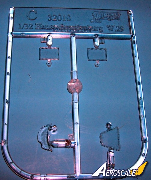
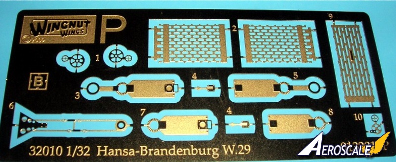
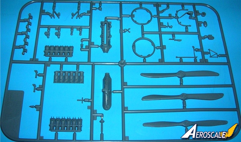
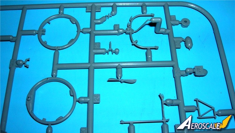
Kit Contents
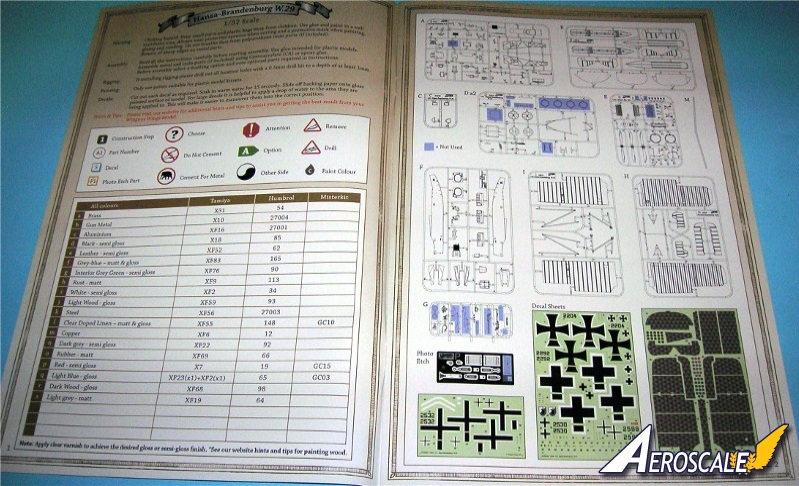
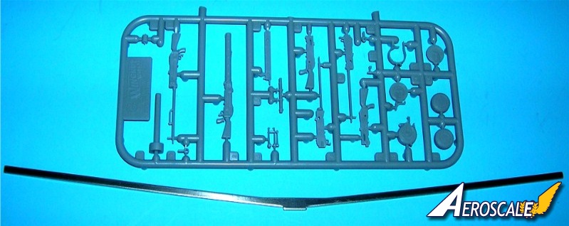
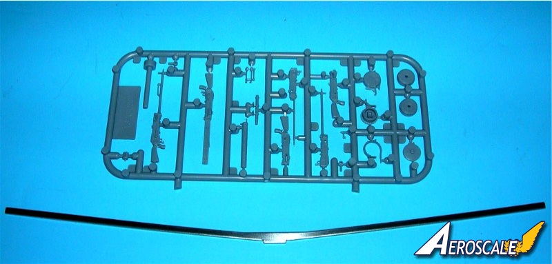
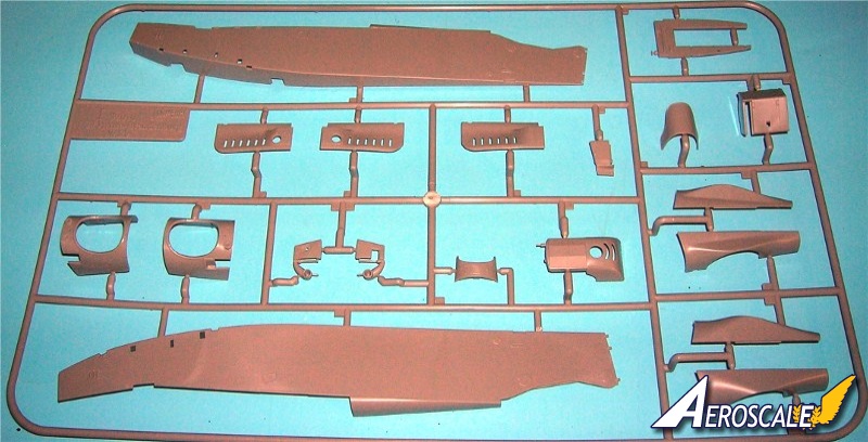
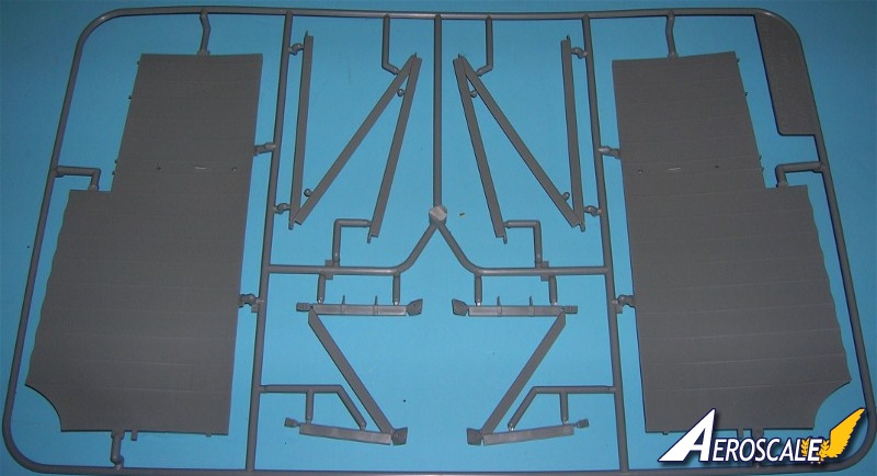
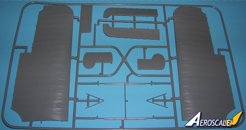
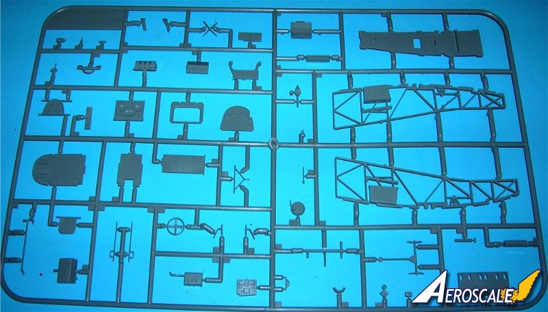
When cracking open the box it is evident that you are faced with another fine kit from Wingnut Wings with the usual fine box art. The contents fill the box to the top with each sprue being individually sealed in a plastic bag, with all the individual bags are in another sealed bag. Decals are on the bottom of the box protected by their own clear sleeve then covered with the instruction manual which again is in its own wrapping. The instruction book is a comprehensive reference with photos of original aircraft. Instructions are clearly written and illustrated but it is important to read the instructions several times before beginning. A paint guide is included plus a small fret of PE parts. This is a beautifully presented high quality and very well detailed kit. Plastic parts are listed as PP PE are simply P in this review
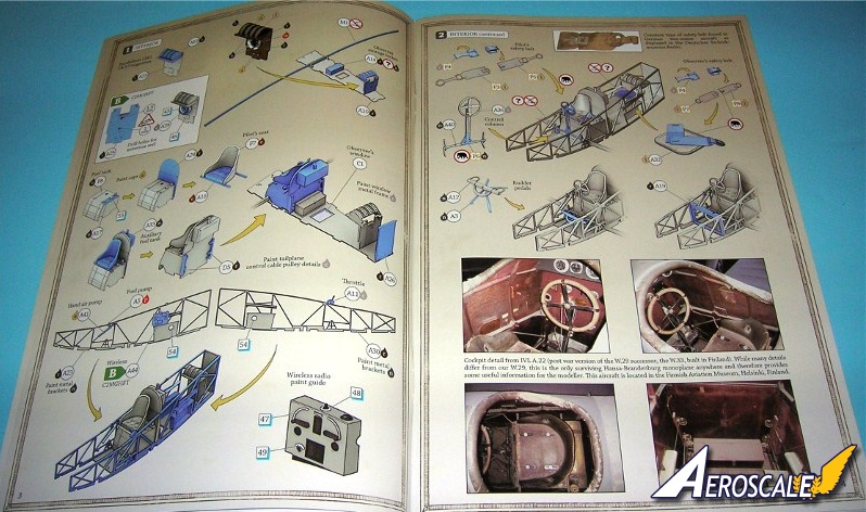
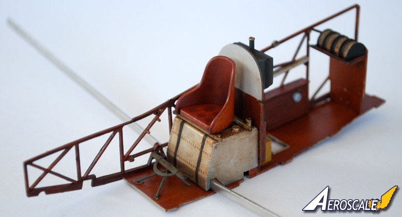
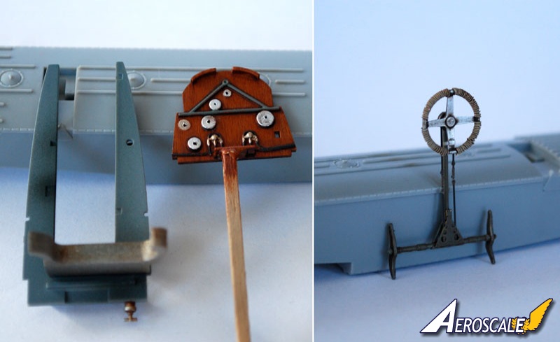
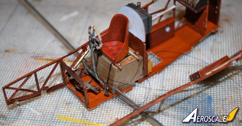
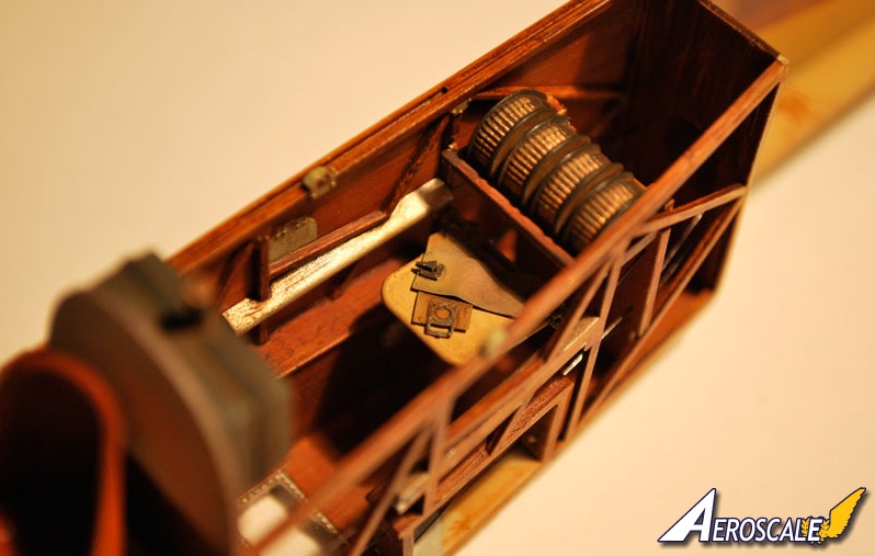
Page 3. Step 1. Interior assembles the cockpit flooring (PP A 10), rear bulkhead (PP A 25)and tray for spare Parabellum ammunition drums (PP A 13). Note for the C2MG (2 machine guns) HFT you have the wireless radio antenna reel (PP A 29). The fuel tank (PP A 17 & F 8) is the basis for the pilots seat (PP F 7) support. Adding the bulkhead (PP A 24), seat cushion (PP A 16). The auxiliary fuel tank (PP A 33) and then the tail plane control cable pulleys. (PP D 5 X 2). these guide pulleys for the control cables needed to be opened up to allow the cables to run behind the pulley. Drill a 0.3mm hole and using a very sharp No.11 scalpel blade elongate the holes and squared off the end next to the timber support, this gives a much better look and closer to what photographic evidence shows. Painting will highlight the pulley support brackets and the pulleys themselves. Note the wireless radio (PP A 44) is only used when 2 machine guns (1 @ Spandau & Parabellum) are employed. If three Machine guns (2 Spandau & 1 Parabellum) are used the wireless was not mounted. The interior fuselage structures (PP A 23 & 30) have details to be considered, such as fuel tank air pressure hand pump (PP A 41) and throttle quadrant (PP A 11) that could do with a bit of routing out.
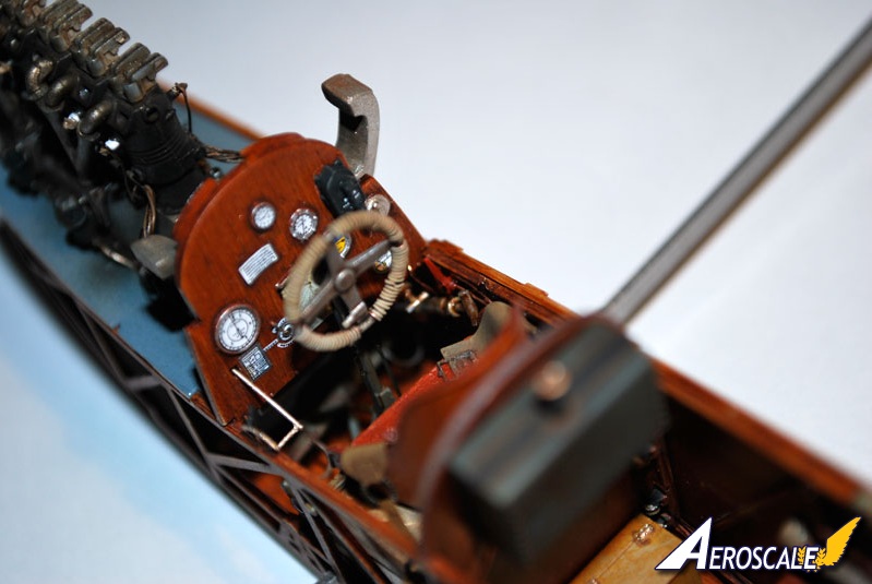
Page 4. Step 2. Interior continues with the lap belts (P 3 5, 7 & 8). The steering wheel column has a reinforcement plate (P 6) at the bottom of the column (PP A 40). The steering wheel itself could do with a wrap of fine wire between the four arms on the outer perimeter. This represents cushion wraps.
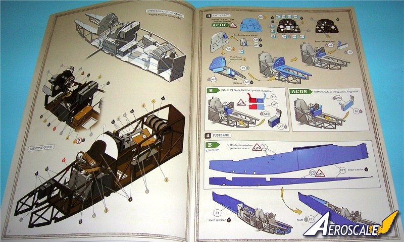
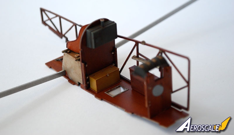
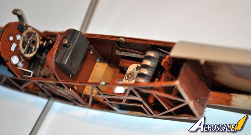
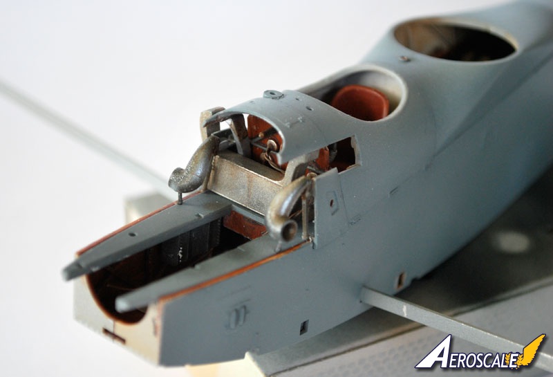
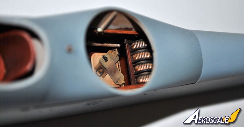
Page 5. Interior rigging and colour notation guide. As noted there is not any rigging material included. To make things a bit simpler try threading the control lines prior to putting the fuselage half on permanently. The guide pulleys for the control cables do not line up with the hole in the bulkhead as marked by WNW. The two boxes at the rear need slots cut in the back to allow the control cables to run rearward, if this wasnt done the cables would run in front of the boxes rubbing on the boxes. The metal cable cover/protector just above the boxes also needs to be hollowed out at the back to allow the cable to run behind. There are no indicators on the rear most bulkhead to indicate where the holes go for the control cables.
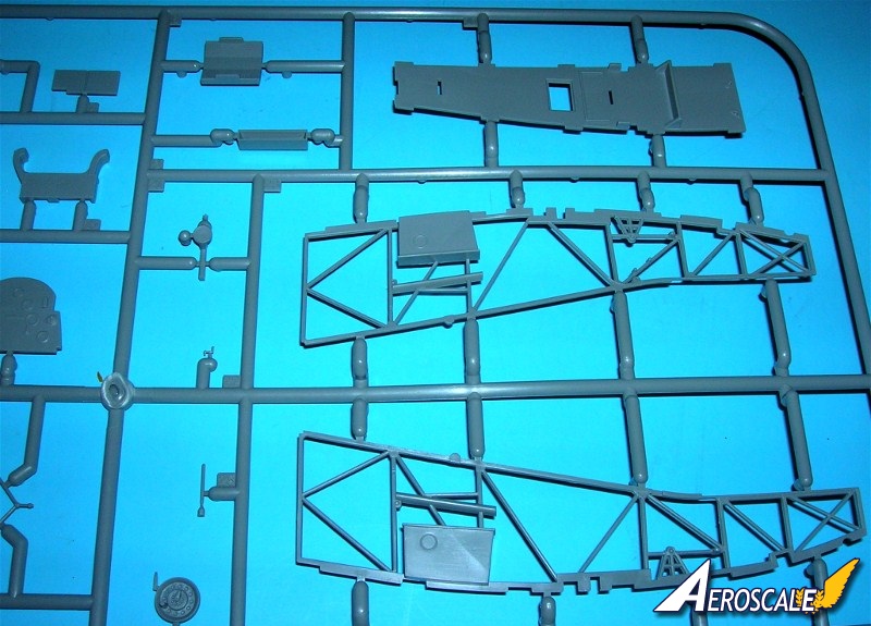
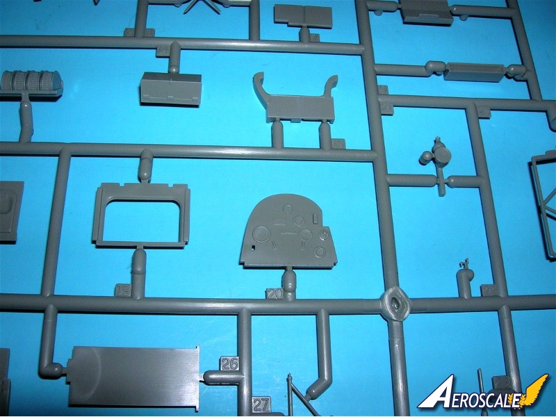
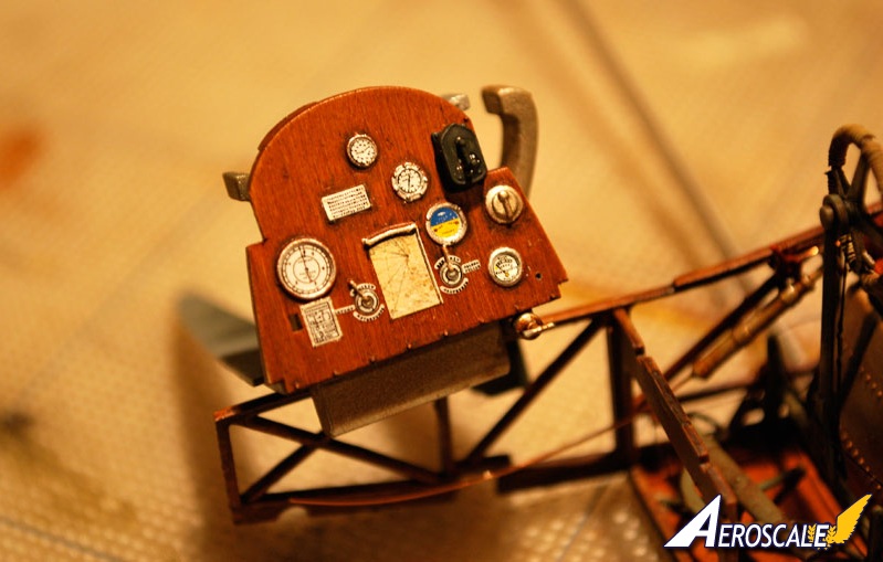
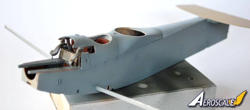
Page 6 Steps 3 & 4. The engine compartment, Instrument panel and basic fuselage details. Whether you are doing the 2 or 3 gun version there are considerations to follow here. The fuselage halves fit together well but make sure you remove any dried paint from seam contact areas. The tolerances are tight. As with the rigging there should be no contacts on the face of the internal framing (PP A 23 & 30) that will keep the fuselage halves from closing around the internal cockpit structure assembly (See step 2). The forward firing Spandaus have ammunition magazines (PP A 7 & 15)and need to be altered if you are doing the 2 or 3 gun version
Page 7. Step 5. Gun setup details and upper decking. The additions of inset images in the WNW instruction books are invaluable. And makes this a historical reference the likes we have never seen in our genre. Variations are noted as green bullets for the chosen profile you wish to model A-E.
Page 8. Images of airframe prototype 2206 with Mercedes D.IIIa. The major advantage to these images is the standard scheme even set by this prototype that followed through the production.
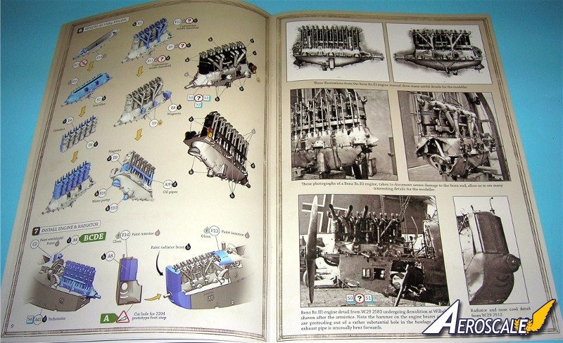
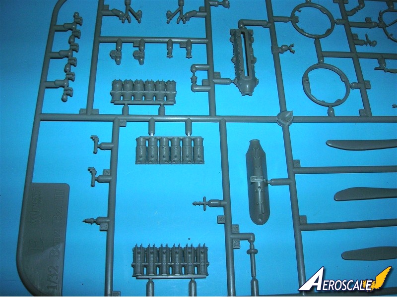
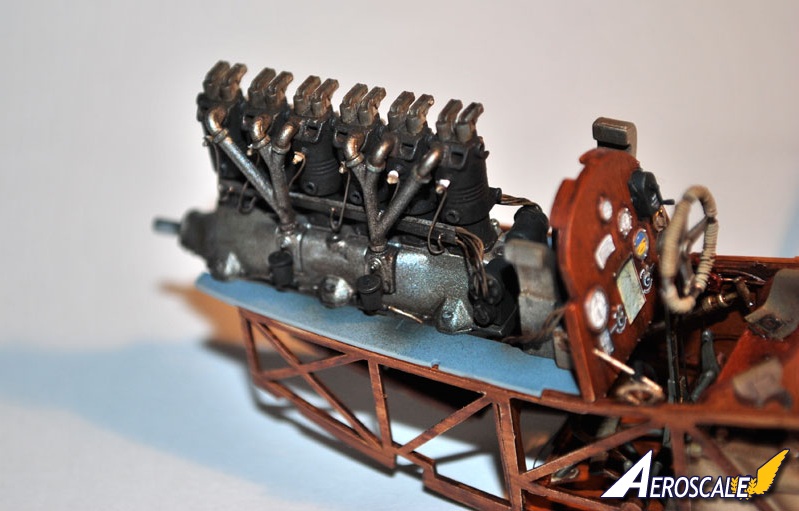
Page 9. Steps 6 & 7. Benz Bz.III engine build up and installation is typical for WNW kit production. Sprue E is usually the parts for the Engine to your specific kit. Crank shaft (PP E 13) and the bottom of the crank case (PP E 14) go together without glue for the shaft to rotate freely. Graphite here is a nice touch. The Fuel filter (PP E 1) should have a simulated fuel line (solder works well) running back to the fuel tank under the pilots seat ( see Step 1). Ignition wires can be plotted like all of the WNW 1:32 kits. Consider adding these should you decide to leave the engine cowlings off for display. Water pump (PP E 16) and oil pump (PP E 10) supply lines should be added as well. I will use cut metal rod to represent the pushrods. The carburetor intakes on most German inline engine aircraft were often wrapped in tar soaked asbestos fabric rope. It kept the engine heat from affecting the air and fuel mix from igniting before entering the cylinder heads. But with these aircraft operating in the channel and North Atlantic this was not an issue. Carburetor intakes (PP E 11 & 12 ) should be bare metal or over-painted for rust concerns. The breather filter and pipe unit (PP A 4) was positioned at on the top forward deck because the engine sat so close to the water when the aircraft took off or landed. Otherwise the carburetors could easily be swamped by choppy waters or heavy swells. You can add spark leads, and the lead wire channel from scratch. WNW did not include these. The following is a good description of how to detail this motor by Aeroscale member Desmond Delatorre.
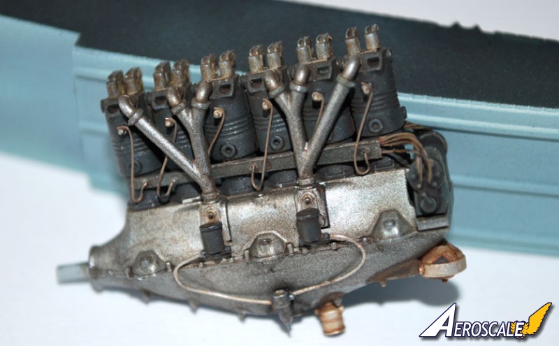
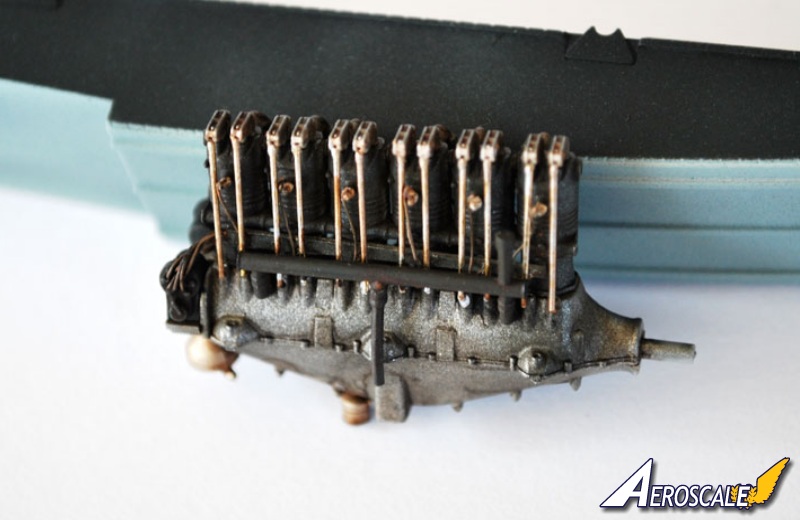
. . . If you want to add rocker arm supports drill 0.3mm holes through the center of each moulded support, I drilled down about 3mm. I then removed the moulded section but left just a small amount close to the cylinder, I sanded the area smooth where the pieces were removed. Next I need to fill the holes on the top of each cylinder so I glued the rocker and valve spring assemblies in place, once dry I removed the assemblies flush with the cylinder heads, a light sand will get it smooth and level, keep the removed sections as the rocker arms will be used. I now drilled 0.5mm holes in the top of each cylinder where the valve stems will go along with the valve springs, I drilled these holes right through the cylinder head so it makes it easier to install the valve stems. I made the valve stems from 0.5mm brass tube, it doesnt matter about the length as it will pass through the cylinder head into the cylinder, I placed a small brass washer over the tube to act as a spring retainer, these washer are 1.15mm in diameter with a 0.6mm hole, CA holds them in place. I tightly wrapped a length of 0.18mm wire around a 0.7mm drill bit, Then I cut the spring to a length of 1.0mm. This spring is then placed over the brass tube and the unit inserted into the hole in the cylinder head, and there you have it, one valve spring and valve stem. The extra length on top of the brass tube is very handy for holding the assembly with tweezers or pliers for insertion into the cylinder, this will be removed once all valve spring assemblies are fixed in position.
I have fixed all the valve springs in position using CA. I cut the excess brass tube from the top of the valve springs and sanded them flat. I am modifying the rockers by cutting a slot into each one, I also drilled a 0.35mm hole in the bottom of each rocker so it will sit on the rocker support tubes. I used 0.3mm brass tube for the rocker supports and fixed them with CA. I drilled 4.5mm holes into the crank case and inserted lengths of 0.4mm brass tube for push rods, these will be adjusted and glued once the rockers are fixed in position. I have positioned the rockers just for a trial fit to see if any adjustments are needed before they are fixed permanently. This has been a lot of work so far but I believe it will be worth the effort.
The rocker assemblies are now all fixed, a drop of CA on top of each valve spring and on the rocker support holds them firmly in place. The push rods are dry fitted, the top of each push rod had to be flattened to allow them to fit into the small slot in the rockers. . . The engine locating lugs fitted very well and makes engine placement very easy. The small cowling behind the engine in front of the windscreen (PP F 13) required a bit of sanding to get it to sit flush with the mating panel, it was sitting way to high in comparison with the rest of the airframe. It was a simple matter of sanding the inside of the cowl and test fitting until it was right . . .
Page 10. Photo images of Bz III are a great reference to specific details.
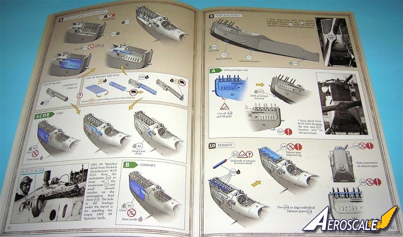
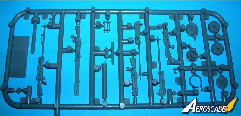
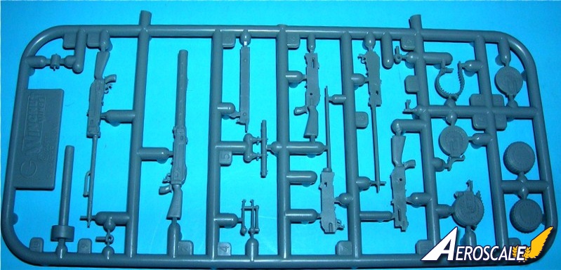
Page 11. Step 8. We see the fuselage details and forward firing armament. If you do a lot to the engine why not leave the engine cowlings off for display? The 2 D sprues in this kit offer you beaching fixtures not found in any other kit. The Naval 7.92mm Spandau Maxims (PP D 17 X 2 or PP 20 X 2 & P 1 & 2 X 2) were beefier in appearance than the Luftstreitkräfte standard 7.92mm. Typically they were to use the ammunirtion needed for specific targets. The C3MG had the two forward firing guns one was to carry tracers & ball rounds in one. In the other gun armour piercing rounds. The 13mm Spandau was designed to penetrate a ships upper plating but came too late in developement to be operational. One modeler says, . . . The mounting of the gun on the (pilot's) left side of the aircraft proved difficult, I had to some trimming of the left side gun mount to allow its breech to sit upright, also the ammunition feed chute for that gun had to be trimmed back to also allow the gun to sit in an upright position, once the modifications were made the gun sat perfectly and was fixed in position. . .
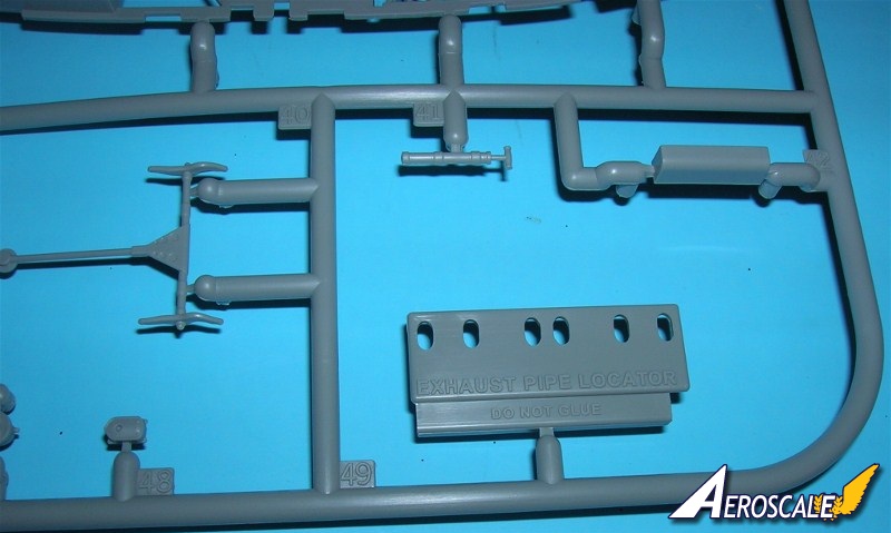
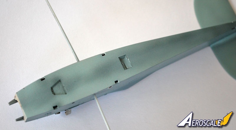
Page 12. Step 9 & 10. More fuselage details include engine access footstep, pilot and observer floor windows. Next is drilling out the individual exhaust pipes (PP D 22 X 6) and a guide placement template to help keep things lined up. Do not glue this in place it is to be removed after the exhaust pipes (PP D 22 X 6) are set and cured.
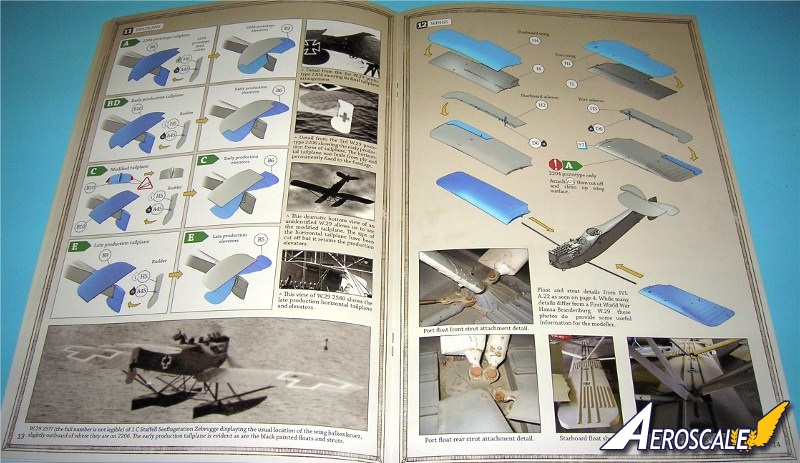
Page 13. Step 11. Next is the various applications for tailplane units according to the profile you have chosen to build. Be careful and do not get these confused.
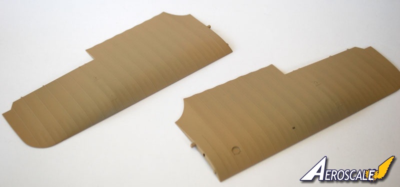
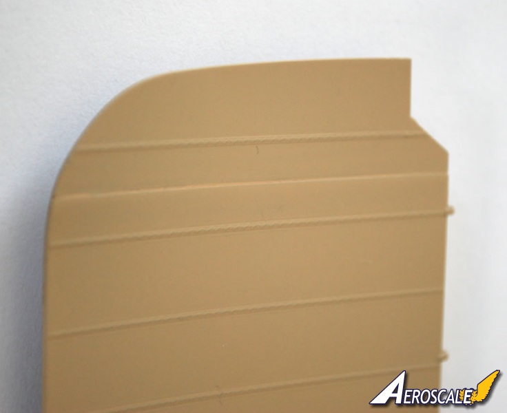
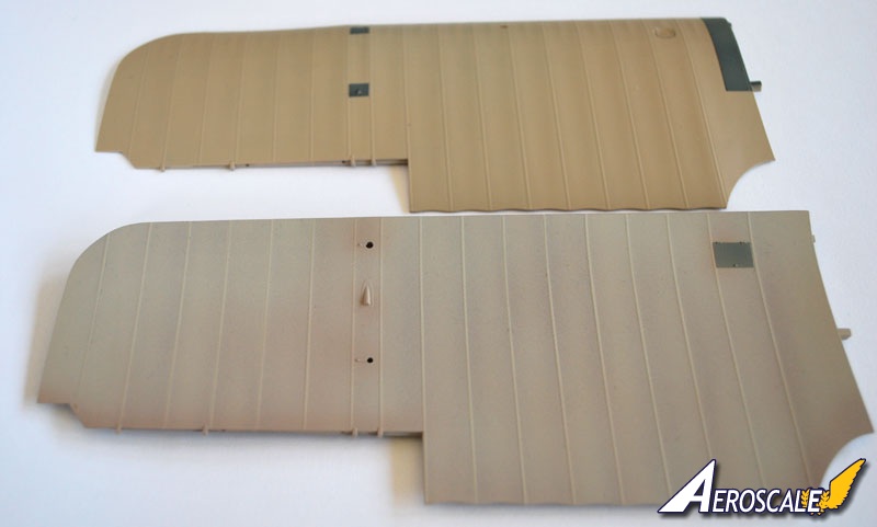
Page 14. Step 12. Wing assembly and attachments. One fellow wrote, . . .So far it has been pretty straightforward, with only one slight hitch as I primed the wings I noticed a slight step where they meet at the seam underneath. . . the fit is perfect. These are large wings and they span 42cm, and make the fuselage look small. Remember to clean up all the sprue attachment points, which were quite large. . .
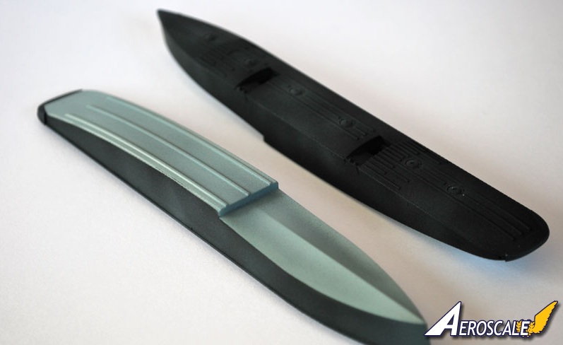
Page 15 Step 13. Float assembly and attachments. Because of the very close tolerances WNW have engineered into this kit, it is extremely important to remove all traces of paint from the strut locating pins and from the locating holes, if not, the fit will be tight and breakages could occur. Dry fit the struts before gluing and do not force the fit.
Page 16. Step 14. C2MGHFT fuselage details. This deals with the wireless radio generator and antenna (PP E 24,28 & 30).
Page 16. Step 15. Observers LMG 14/17 Parabellum armament and ring mount. One fellow wrote, . . . Instead of painting the bullet belt I cut a strip 0.5mm wide from a common tea bag. I glued the front end onto the drum then wrapped the strip around the drum and glued the other end. Once the glue was dry I applied a small amount of water to the strip then pushed it into the bullet with my finger, this leaves the indentations between the bullets, when dry it will retain the shape. I will leave the belt the natural colour as it does look a little like linen. . . HGW are you listening?
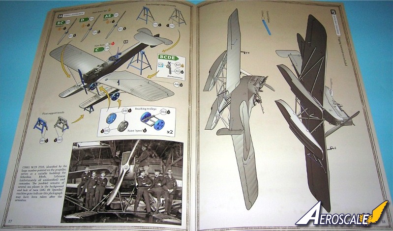
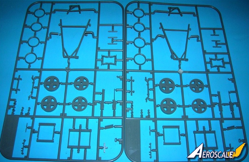
Page 17. Step 16. Final assembly. This beaching gear (PP D 2, 10- 15 X 2), is not necessary as the model sits fine on the floats, but for a more authentic look the beaching gear is a great addition to the kit, perfect for those wishing to do a diorama.
Page 18. Step 17 Rigging.
A simple cross brace between the floats and the aileron actuation wires is all that is noted.
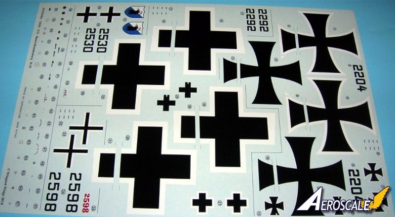
Kit Profiles
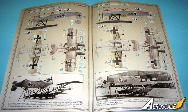
Page 19. Profile A. Hansa Brandenburg W.29 2204 C3MG prototype, April 1918.
Page 20. Profile B. Hansa Brandenburg W.29 2292 C2MGHFT, July 1918.
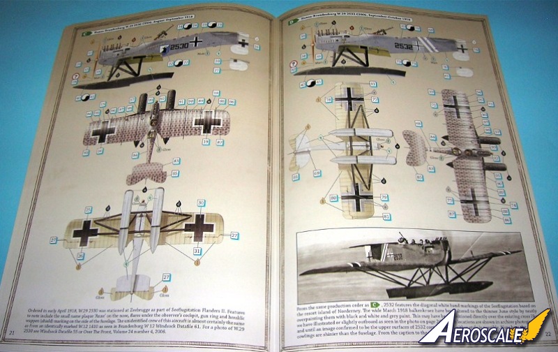
Page 21. Profile C. Hansa Brandenburg W.29 2530 C3MG, August - September 1918.
Page 22. Profile D. Hansa Brandenburg W.29 2532 C3MG, September- October 1918.
Page 23. Profile E. Hansa Brandenburg W.29 2598 C3MG, October - November 1918.
References
Cross & Cockade USA Vol. 20 #2 Pp.107 - 135. 1979.
Brandenburg W.29 Datafile 55, P.M Grosz, 1996.
Over The Front, Volume 24 number 4, 2006
German Knights of the Air 1914-1918, The Holders of the Orden Pour le Merite by Terry C. Treadwell & Alan C. Wood Barnes & Noble, Inc. 1997
German Naval Air Service Vintage Aviation Fotofax by Alex Imrie, Arms and Armour Press 1989
1914-18 Aviation Heritage Trust - Colin Owers
The Vintage Aviator LTD - Private Collections.
My sincere thanks to;
Aeroscale member Michael Terfors for allowing me to use some of his build images and quotes
Aeroscale member Des Delatorre for allowing me to quote him.
When contacting manufacturers and publishers please mention you saw this review at AEROSCALE
Highs: Great subject matter, Fine design at details. Clear instructions. Quality decals. Inscale details for the interior and engine. Lows: Minor fit issues with the pilot's left side Spandau MG and a small upper deck cowling. Verdict: This kit presents a great opportunity for any modeler. Seldom modeled in any scale we have a rare treat to have this quality kit on the shelves.
Our Thanks to Wingnut Wings! This item was provided by them for the purpose of having it reviewed on this KitMaker Network site. If you would like your kit, book, or product reviewed, please contact us.
About Stephen T. Lawson (JackFlash) FROM: COLORADO, UNITED STATES
I was building Off topic jet age kits at the age of 7. I remember building my first WWI kit way back in 1964-5 at the age of 8-9. Hundreds of 1/72 scale Revell and Airfix kits later my eyes started to change and I wanted to do more detail. With the advent of DML / Dragon and Eduard I sold off my ...
Greetings all,
Just a note from the Production Manager at WIngnut Wings, Mr. Richard Alexander! (No where else but Aeroscale folks!)
The machine guns on the H-B W.29 are infact (as mentioned in the previous post) examples of the IMG 05 Spandau (the "L" is lower case) with the classic flat topped breech. (Seen on most 1914 - 1916 German machines). The sea coast German Navy did not seem to use the later 08/15 LMG Spandau as did the land based Marine Feld Jastas.
Oh drat I wrapped my steering wheel but like Richard notes it does ad a bit of neatness, and it was fun to do I will retain the kits IMG 05 Spandau though...
Thanks for posting this info Stephen
Mikael
Well done Stephen. Good review.
I am building my WNW kits in the order they were releaed so the W.29 is a way off yet as I have just started the Albatross D.Va, which I will add to the KotS Campaign tomorrow. That makes six kits if I can finish the SPAD and Albie.
Cheers
Warren
Jackflash:
Thank you for the answer. Now I can properly plumb my W29 even if it is never seen.
Smart Idea, how did you find this out? None of my documents mentions this (or I just couldn't find it. I have a "few" books and clippings of the era, but not that much on the B-H technical data.
Thanks for the info
Captn Tommy
Tough news for HB W.29 fans.
"Thank you for your enquiry about the availability of 32010
Hansa-Brandenburg W.29.
This model is now sold out and no longer available to order. Currently
we do not have plans to reissue this model but at some time in the
future we will release a Special Edition version.
The Special Edition will include additional decal schemes, resin figures
and nearly 200 photo-etch detail parts. We do not have a release date
set for the Special Edition at this time.
Regards
Dave Johnson
Warehouse Operations Manager
Wingnut Wings
PO Box 15-319, Miramar 6022,
Wellington , New Zealand"
I think the Hansa has sold to many non-regular WWI builders, that would otherwise be a bit apprehensive about rigging and upper wings... thus selling out (very) quickly. Wonder if this means there will be other monoplanes sans rigging in future from WNW - like the Junkers DI? I would love one of those in 1:32 myself.
Mikael


Comments