F-16 Fighting Falcon was developed as a result of the Lightweight Fighter Program announced in January 1971. As part of this program two General Dynamics YF-16 prototypes were built and they competed against Northrops YF-17 planes. On January 13th 1975 YF-16 has been announced as the winner of the contest, which in the meantime was renamed to Air Combat Fighter (ACF). The first F-16A / Full Scale Development aircraft was flown on December 8th, 1976 and the first operational F-16A was delivered in January 1979 to the 388th Tactical Fighter Wing at Hill Air Force Base, Utah.
Since its first flight Fighting Falcon, also known unofficially as Viper, is constantly modernized and updated. Those modifications however are not clearly reflected in a version number, as only recently the E and F models were introduced and all previous single-seat models were carrying A and C designations (B and D for two-seaters respectively). This is why it is very important to note the block production number, as in case of F-16 it is most important information to properly identify features of the variant.
F-16A/Bs were built in five blocks: 1, 5, 10, 15 and 20. The F-16C/D designation was introduced with block 25. Beginning with Block 30 new engines were installed in Vipers. All previous variants were powered by Pratt & Whitney F100 engines and Block 30 aircraft were first F-16s equipped with General Electric F110 engine. 75% of new Vipers produced for US Air Force were Block 30 GE-powered machines, but remaining 25% still had PE engines - these machines were known as Block 32. After the introduction of Block 30 aircraft to service it became obvious that the air consumption of GE engine, which was significantly higher than this of PE engine, necessitated in redesign of air intake. Beginning with sub-block 30D larger, so called big mouth, air intake was installed. Subsequent production blocks maintained similar designation convention, where block 30 and 40 aircraft were powered by GE engines and featured large intakes, while block 42 and 52 planes were PE-powered and had classic small intakes. Block 40/42 aircraft introduced in 1989 were known also as Night Falcons because of their enhanced night/all-weather capabilities achieved by installation of LANTIRN pods. Block 50/52 feature, among other updates, upgraded radar and Improved Performance Engines, the F110-GE-129 for the Block 50 or the F100-PW-229 for the Block 52.
In May 1993 deliveries of Block 50D/52D began. These aircraft, unofficially known as F-16CJ/DJ have added capabilities, which allow them to perform Wild Weasel (SEAD - Suppression of Enemy Air Defense and DEAD - Destruction of Enemy Air Defense) missions thanks to a full integration of HARM missile avionics/Launcher Interface Computer (ALIC) and associated systems / pods. All but the earliest Block 50 models have been upgraded to Block 50D standard.
New Tamiya kit represents F-16CJ Block 50D aircraft (although the D letter was omitted from the kit name).
The kit
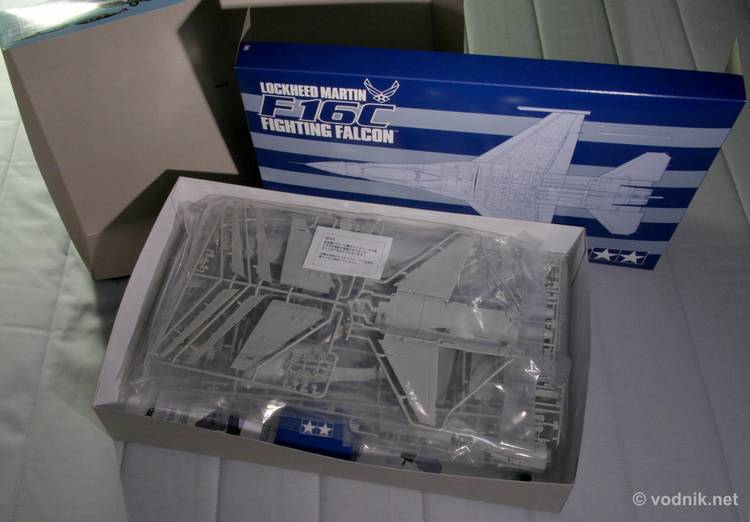
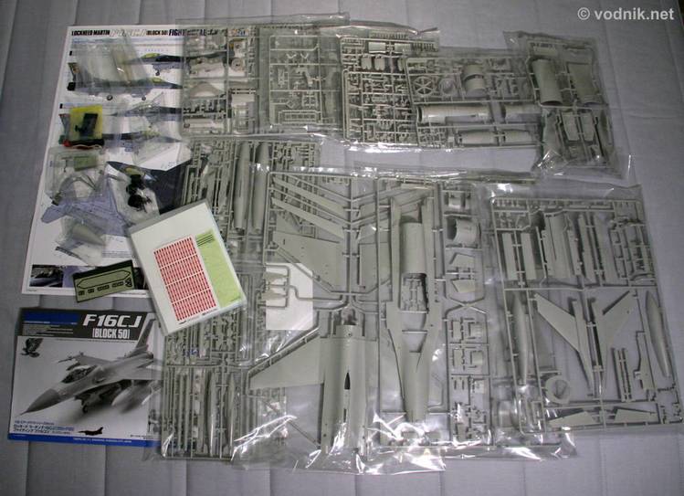
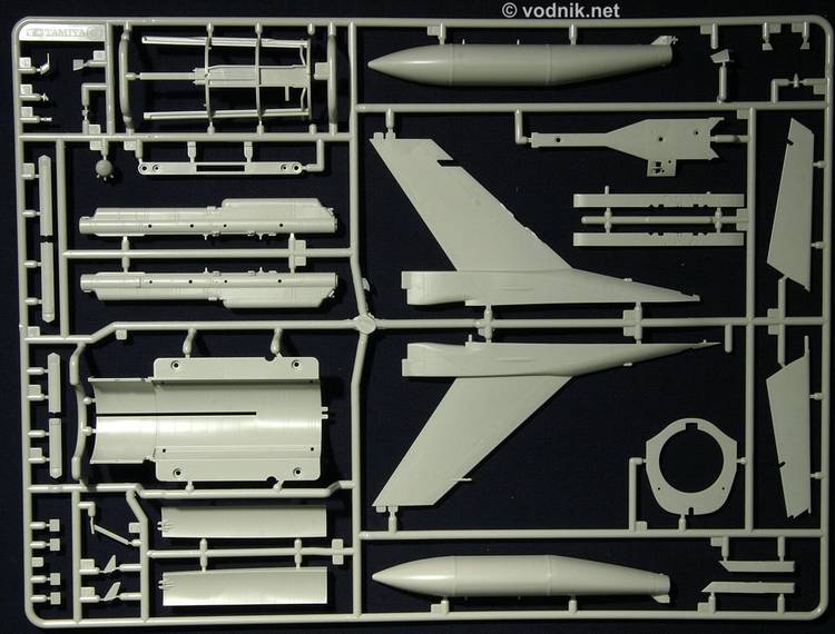
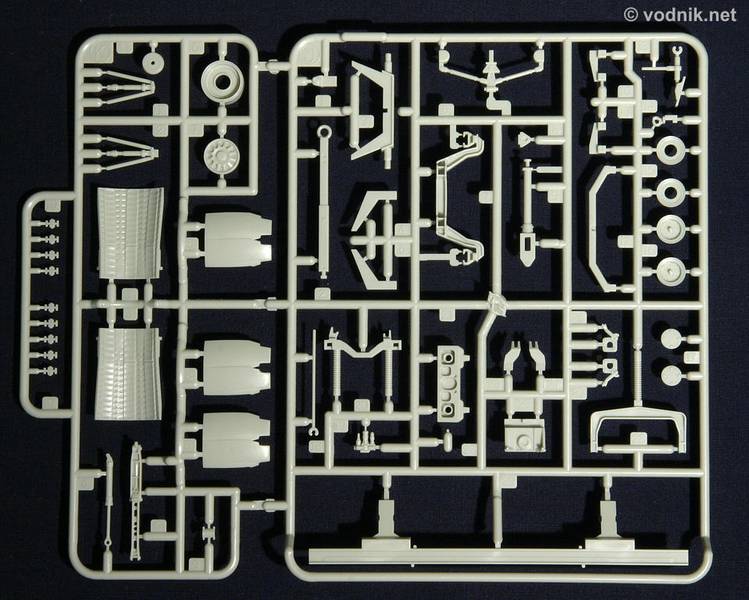
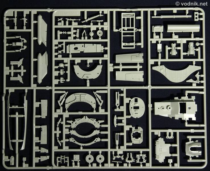
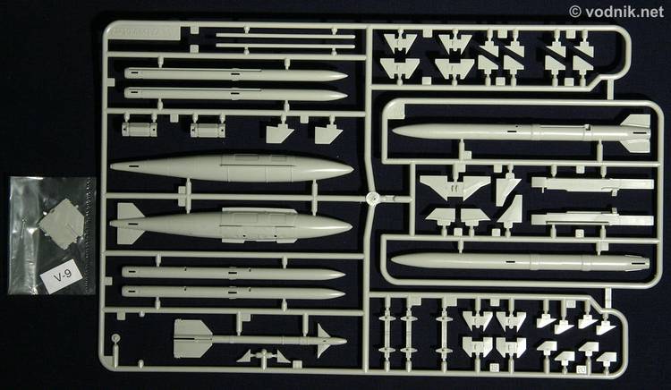
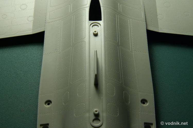
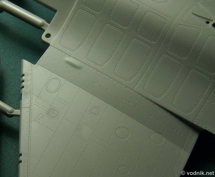
The kit comes in a quite large box with a very nice picture of 79th Fighter Squadron aircraft in Tiger Meet of the Americas 2001 colors on the lid. The box is about the same size as other Tamiya 1/32 scale jets. After opening the box I saw... well... another box. Or actually the inner lid. This inner lid has pre-cut holes in it and once properly bent to shape can later serve as a storage base to hold completed model in the box. But at this moment what I wanted to see was PLASTIC! So I removed the inner lid and underneath was exactly it - a lot of light gray plastic. Each sprue is individually bagged, except for those that are provided in two copies - in such case both copies are in one bag. There are 10 plastic bags in the box with 13 sprues inside them. But there is even more sprue letters listed in instructions - thats because some of smaller individually named sprues are molded together and make up de-facto larger sprues. For some reason in my kit parts V9, which are AIM-9 stabilizers were not attached to the sprue (they should be on V sprue), but provided separately in a small bag with the piece of paper inside (with part number printed on it). Quick look on parts on sprues reveals plethora of beautiful crisp details and delicate but well defined engraved panel lines and rivets. Everything we expect from the modern kit and even more!
Under the bagged sprues there is a cardboard box with all additional parts inside. Here is what I found inside it:
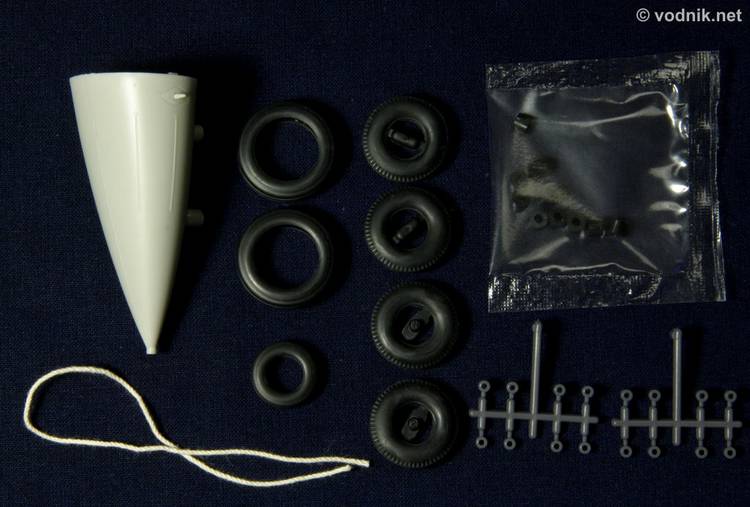
- plastic bag with seven vinyl tires (three for airplane and four for engine dolly) and two small sprues with tiny poly caps,
- clear plastic container with die-cast metal landing gear parts and metal weight for the aircraft nose,
- a bag with the radome molded as single part with tiny angle of attack antennas molded on,
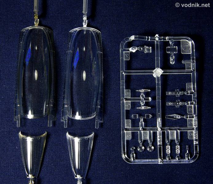
- two bags with two sets of clear canopy parts - one of them tinted. Canopy parts are very well protected, each in individual bag.
- a bag with clear parts sprue,
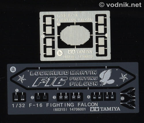
- a bag with two photoetched frets,
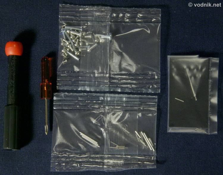
- a bag with a screwdriver, length of twine and several smaller plastic bags inside. In those bags are additional poly caps plus various small metal parts: screws, rivets, shafts and machined aluminum Pitot tube (well, actually it is not a tube in the model, as it is solid... oh, well...).
Under all the stuff mentioned above, on the bottom of kit box, is another plastic bag - flat this time, as it contains two decal sheets (relatively small for such large kit), a paper sheet with printed RBF tags and a sheet of painting masks for the canopy.
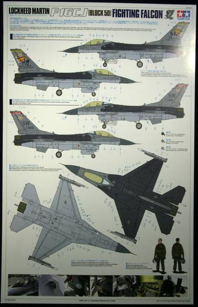
The last three items in the box are: small sheet of paper with usual safety instructions, 32 page A-4 size instructions booklet plus painting and decaling guide printed in full color on both sides of large high quality paper sheet, with a bonus in form of a lot of useful photos of real aircraft details on it.
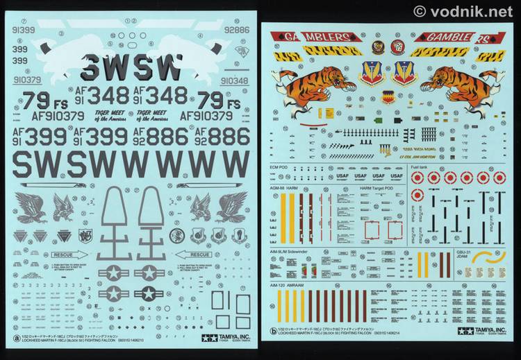
Markings on decal sheets are provided for four aircraft:
1. 79th Fighter Squadron, 20th Fighter Wing, USAF, Tiger Meet of Americas, Buckley AFB, Colorado, USA, August 2001 - with beautifully printed colorful tiger for the tail fin,
2. 77th Fighter Squadron, 20th Fighter Wing, USAF, Prince Sultan AB, Saudi Arabia, Operation Iraqi Freedom, 2003
3. 13th Fighter Squadron, 35th Fighter Wing, USAF, Prince Sultan AB, Saudi Arabia, Operation Iraqi Freedom, 2003
4. 14th Fighter Squadron, 35th Fighter Wing, USAF, Prince Sultan AB, Saudi Arabia, Operation Iraqi Freedom, 2003.
We also get full set of very well printed stencil decals for the aircraft and all external stores. Decal film seems to be quite typical for Tamiya and this means that it is a bit on the thick side.
To make my life easier I will now describe the kit in more detail in the order of assembly described in instructions. The instructions booklet starts with the aircraft history in four languages (Japanese, English, German and French), followed by short description of all dangly bits provided in the kit (weapons, fuel tanks, pods) and decaling guide for them. Next is general model painting instructions, list of required Tamiya paints (42 listed!), short read before assembly instructions and a list of recommended tools. Only after all these introductions, 63 step actual assembly instructions start.
Assembly diagrams are very clear, with a lot of useful and important information added in text form. Gluing surfaces are shaded in blue on all pictures, what can be extremely important to avoid incorrectly attached parts. Painting instructions for all detail parts are also provided on diagrams in all assembly steps.
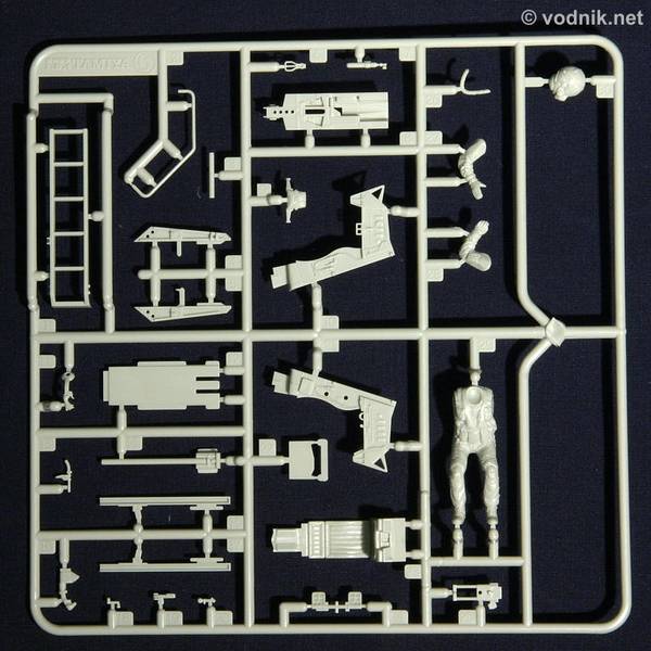
Assembly starts not with the aircraft, but with the engine dolly (6 instructions steps). It is very detailed and many components remain moveable after assembly - it is a nice little kit itself. Dolly can be assembled in two configurations - for raised or lowered engine. To display engine lowered on the dolly modeler has to modify one set of engine mounts / jacks, as there are two identical sets provided, and shafts in one have to be shortened to make lowered version. As there are two sets provided and they are attached to the dolly without using glue, it is possible to quickly and easily reconfigure the dolly to any of configurations by swapping jack parts.
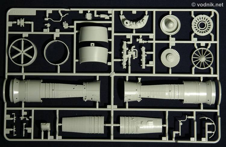
Next five steps describe the assembly of the F110-GE-129 engine. This is nicely detailed, although Im sure that super-detailers among you will still find a lot of space to show their talents here. Exhaust nozzle itself is composed of eleven detailed parts. Some engine parts are detachable after assembly and two versions for these parts are provided - one for engine displayed on the dolly, and the other for engine installed in the aircraft. It is possible to display engine in three ways - in the aircraft, on the dolly in raised position or on the dolly in lowered position and thanks to detachable parts you can reconfigure your display of finished model to any of them. I personally dont play with my models this way once they are finished, but for some it may significantly increase the coolness factor of the kit. I would prefer to get two sets of inner engine and exhaust parts to be able to display my finished model with the engine inside (at least its visible components), but with the second complete engine displayed on the dolly. To do this however I will need to order additional sprues from Tamiya...
The assembly of actual airplane model starts in step 13 with main landing gear well. It is nicely detailed with most devices and structural components present and accurate - many of them as separate parts - but almost void of cables and pipework. Modelers building the kit out of the box can be slightly disappointed, as the lack of pipes and cables might make the gear well look a bit bare inside. More skilled modelers should have no problems adding missing details using e.g. solder wire.
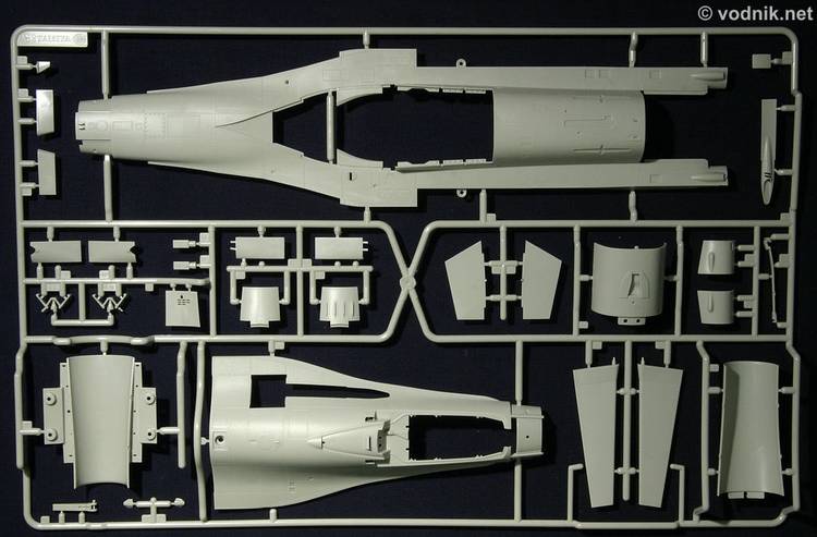
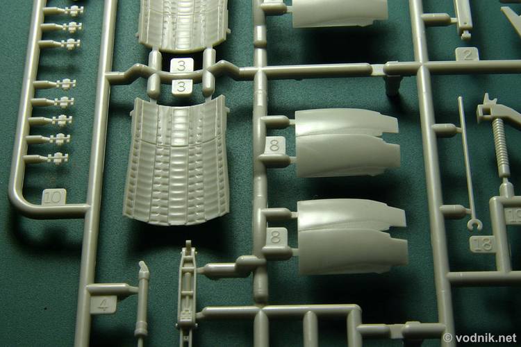
As the engine is removable Tamiya provided parts to build complete air duct and engine bay inside the fuselage - from the intake to the exhaust. Parts are reasonably detailed inside. Engine bay and rear part of intake air duct are secured to the lower fuselage with eight screws. The lower fuselage part is the longest part in the kit - it includes almost the whole length of the fuselage, as it starts behind the radome and ends on airbrake hinges. Nose landing gear well is attached to the lower part of front air intake duct and gear strut has to be installed before the intake is inserted in the fuselage. This means that some care is needed during following assembly steps to avoid damaging the strut (not likely as it is die-cast metal) and surrounding parts (much more likely). Nose gear well is similar to main gear well in one respect - there is no cabling / pipework details present, but all the structural components are in place. It remains to be seen how difficult it will be to remove the seam that appears after gluing two (upper and lower) intake duct parts together. The MCID big mouth intake lip is a separate part and it should make painting it much easier.
Once intake parts, together with nose gear, are attached to the lower fuselage, we are supposed to finish installation of main landing gear components. This means that starting from instructions step 26 we have complete landing gear in place, what can potentially make later assembly difficult. Die-cast metal landing gear struts are well detailed and there is several detail plastic parts attached to them, what means that use of super glue is necessary. All three wheels are attached to struts using screws and can rotate freely after assembly. This means that wheel chocks provided in the model are not only for show, but are also useful to make sure that our Viper does not move on the display shelf! Tires are provided only as vinyl / rubber parts and no plastic ones are provided (as was the case in Academy Hornet kit), so I expect that aftermarket companies will soon offer resin replacements for those who dislike such vinyl parts.
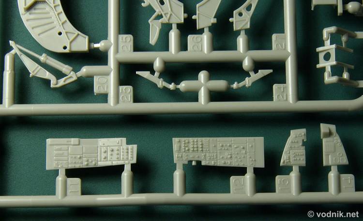
In step 27 the cockpit is built and it is really nice with raised and very accurate details. Side instrument panel tops are attached to the cockpit tub as separate parts, so it should be quite easy for Tamiya to provide different versions of them for other Viper variants in the future. Several parts, like pedals, thrust levers, control stick and some other are also separate parts. Clear parts are provided for HUD and MFDs. We get decals for MFD data. Ejection seat is made of seven parts and definitely looks the part. It is not glued to the cockpit, but slides on its rails and can be detached easily. Seated pilot figure is provided, but for those who prefer to display inhabited cockpits Tamiya included photoetched seat buckles and seatbelts printed on the same tape as canopy masks, what means that they seem to be much too green in color. Completed cockpit is screwed on to the lower fuselage, together with metal ballast.
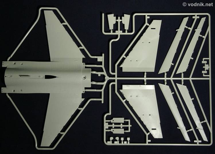
In step 33 front and rear sections of upper fuselage are assembled (again using a screw). There is only one explanation to the fact that the front upper fuselage is separate part - it makes it possible for Tamiya to release the family variant of Viper kit in the future! Rear upper fuselage is molded integrally with upper wing halves.
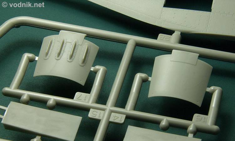
In step 35 upper and lower fuselage parts finally meet. Two poly caps have to be enclosed between fuselage halves - they will be used to attach horizontal stabilizers. Then lower halves of wings are glued to the upper halves and again several poly caps go between wing parts - these will hold wing tank pylons to wings. In following steps highly detailed landing gear doors are attached to the fuselage (main gear doors are correctly bulged) and pylons are assembled and glued to wings. For chaff/flare dispensers on the bottom of the fuselage we get three options - we can use smooth plastic parts for blanking panels to cover them or use one of dispenser parts etched from 0.3 mm thick metal sheet. We get PE parts for both flare and chaff dispensers and it is up to the modelers decision what configuration they choose.
Vulcan cannon and radar unit are assembled next and attached to the fuselage. Radar antenna is provided as photoetched part. The gun barrels are attached with the poly cap and can rotate after assembly. Gun access panel is a separate part, which is not glued to the fuselage, so it can be removed to display the gun details.
All control surfaces are movable in the kit, except for leading edge flaps. These can be attached either extended or retracted, but different tabs have to be removed from the edge of the part for each position. Once the part is modified this way, it can only be attached in this one position. Interesting feature of the kit are static dischargers provided as small thin metal rods. There are three on the trailing edge of each wing plus three on each stabilizer.
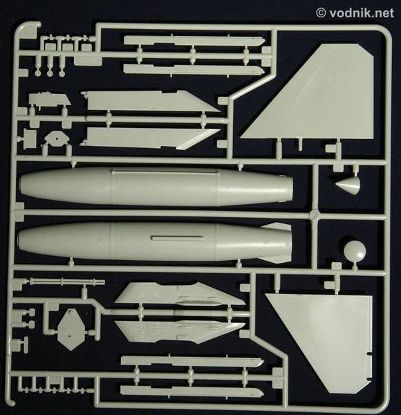
As I already mentioned vertical fin is detachable from the fuselage to facilitate storing the finished model in the kit box. Speed brakes can be assembled open or closed with additional detail parts provided for open position. There are small and shallow ejector pin marks on inner surfaces or speed brakes. Generally in the kit pin marks are very well placed, mostly in areas hidden after assembly, but still a few remain visible here and there and these would need to be filled. Luckily all of them (at least those I found) are in places where it should be rather easy to do.
Assembly of the airplane ends with the radome and canopy. Radome has a hinge, which works similarly to the real thing. This means that the radome can be extended away from the fuselage and then swung to the side. I already mentioned very nice, although solid, machined metal Pitot probe. There is a thin molding seam along the top of each canopy part, which has to be carefully removed. Canopy is designed in such way that it can be attached to the fuselage in either open or closed position without glue. Two canopy actuator parts - one for each canopy position - are provided and they also are attached without glue. This means that you can reconfigure your finished kit to open or closed canopy configuration easily.
I didnt mention earlier that clear parts are provided in the kit for all position lights and landing lights.
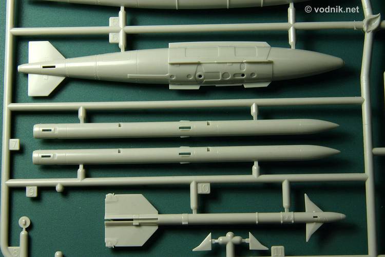
Once the aircraft itself is finished, it is time to attach external stores. In the kit we get:
- four AIM-120 AMRAAMs, with a choice of two fin options to build either B or C variant,
- two AIM-9M Sidewinders,
- two GBU-31 JDAMs,
- two AGM-88 HARMs,
- two 370 gallon wing tanks,
- one 300 gallon centerline tank,
- AN/ALQ-184 ECM pod (beautifully detailed - composed of seven parts),
- AN/ASQ-213 HARM targeting pod.
Missile fins are as usual slightly too thick for scale, but still very thin for plastic parts. Ive seen 1/72 missiles with thicker fins than these! All air-to-air missiles have to be glued to their launchers and there are only four launchers provided, so despite some rumors that were circulating before the kit release, while launchers themselves are detachable from wings (with metal pins enclosed inside pylons and poly caps inside launchers) it is not possible to freely change weapons configuration in finished model - unless you order additional sprues with launcher parts from Tamiya. The only changes possible in finished model are switching HARMs with JDAMs and ECM pod with centerline tank. You can also detach wing tanks with their pylons, but quite large holes remain in wings with nothing to cover them. Also in case you want to build your model in clean configuration and skip installation of all pylons, you need to devise your own way to cover holes in wings. Also note that there are no details on bottom sides of missile launchers, so displaying empty launchers is not possible without some extra detailing work.
Final touches of the model building shown in instructions are assembly of boarding ladder, wheel chocks and Remove Before Flight tags. No guide is given for placement of RBF tags.
Near the end of instructions are directions for storing finished model in the box. This is a very nice feature, which will be particularly useful for all modelers traveling with their models.
On last two pages all part sprues are shown. It is very interesting to notice that there is just one part marked as not used on all sprues. But this single part makes it very clear that more Viper variant kits will follow from Tamiya. This part is a small panel for area between the canopy and radome. In the F-16CJ kit the smooth version of this part is used, but on the B sprue we also get part with four bird slicer IFF antennas!
ACCURACY
I must admit that Im not a Viper expert, so I cant provide detailed analysis of accuracy of new Tamiya kit. But I still made an attempt to at least try to see how close is this kit to the real thing.
To my eyes the diameter of the F110 engine is too small. It does not look quite right on photos of competed Tamiya kit. The diameter of exhaust nozzle is correct, but the rest of the engine seems slightly too thin. I guess it could be a compromise Tamiya accepted to make engine removable from the fuselage.
Almost all panel lines are spot on, but there is at least one area on the fuselage where they are not fully correct. It is a small mistake - Tamiya made fuselage panels located on both sides of vertical fin symmetrical, while in reality there are noticeable differences between panel shapes on starboard and port side of fuselage in this area.
I scaled up 1/48 plans from the Daco Uncovering the Lockheed Martin F-16 A/B/C/D book to 1/32 scale and compared model parts shape to them. Everything fits almost perfectly to plans, except for vertical fin and horizontal stabilizers. The former seems to be slightly too small overall and the latter are slightly different shape. I wonder if an error in scaling up plans could have caused the fins size difference? It is possible, although the difference is quite noticeable (some 4mm in height) and other parts of the model fit very well to the same plan. Most surprising is that earlier I found very similar discrepancies when I compared Hasegawa 1/48 model parts to Daco plans. Could it be that there is an error in Daco plans and not in these models? It seems quite likely to me.
VERDICT
Tamiya definitely have not disappointed modelers with this new release. It is really a masterpiece of injection molding and engineering. Of course I dont know yet how the parts will fit, but I expect the same as in all recent Tamiya kits - and this means almost perfect fit! Some may feel that all the detachable and movable parts are useless gimmicks, which only increase the price of the model. I think that many of these features will actually make the assembly and painting much easier, what makes them quite useful. I also welcome the possibility to keep finished model in its box. I currently do not have display space to keep finished model, but after seeing all the beautiful details in Tamiya Viper I feel I need to build it soon anyway! Tamiyas clever idea means that I can finish my Viper and keep it in the box until I have more proper space available for it.
HIGHLY RECOMMENDED!
Many thanks to RAINBOW TEN online store for their excellent service, which allowed me to write this review less then a week after kit's release in Japan!
ADDENDUM: It was brought to my attention that there is one more potential problem in Tamiya Viper kit: instrument faces on main instrument panel are flat and featureless. There is no molded on detail on them and no decals are provided with instrument faces. It looks like Tamiya planned to provide instrument faces as decals and simply forgot to add them later... I wrote that it is a potential problem, because for many modelers it should be easy to use aftermarket decals, printed instrument faces or simply paint details on instruments, but for many others it may be significant problem, thus it is important to mention it here.
ADDENDUM 2: If you look closely on photo of sprue C you can see that the leading edge of vertical fin is damaged. It looks like some part from other sprue has been pressed against fin part and caused damage to thin fin edge. This is how I found this part in my kit box when I first opened it, so it could have been damaged in transport, or during packing in Tamiya factory - it is difficult to say now. Parts it model reviewed by Michael Benolkin at http://www.cybermodeler.com were similarly damaged. He wrote that "the vertical stab halves had been damaged, probably when it came out of the molds. Great packaging, but not-so-great quality control." In my kit however the plastic bag in which sprue C had been packed was slightly torn/cut near the damage area on the fin part, so the damage was definitely made when the parts were already in the bag. This suggests packing error, not mold release problem. And I assume that quality control is performed before parts are packed. So actually quality control may be OK, but packaging is not! I know that other people were receiving new Viper kits without any damaged parts, so luckily it doesn't appear to be a generic problem.
I let guys at Rainbow Ten, from whom I bought the kit, know about my problem last week and today (or actually yesterday, but I was not home to receive the package) I received complete replacement sprue C from them! It is of course perfect without any blemishes. Please note that today is Tuesday, I emailed RT about the problem last Wednesday. And I'm in Poland, while RT are in Japan!
EXCELLENT SERVICE! Many thanks Rainbow Ten!!!