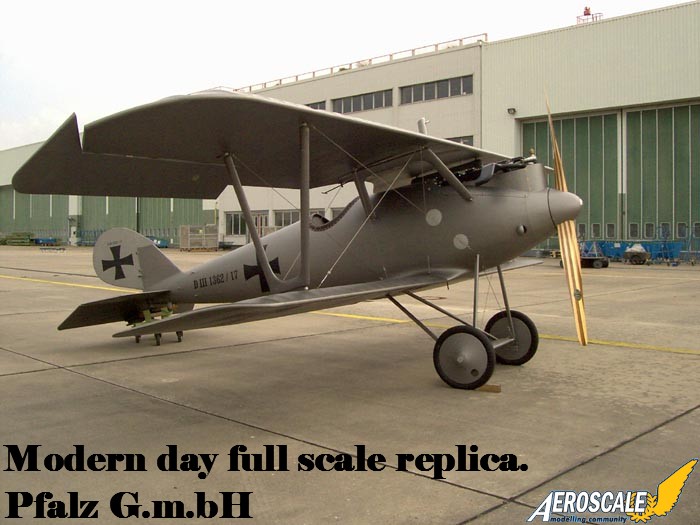
The shark-like profile of the Pfalz D.III appeared on the Western Front in late summer / early autumn 1917. Manufactured by the Pfalz Werke in Bavaria the first examples of the early production types were evidently saddled with the obsolete Mercedes D.IIIa 170hp inline six.
Several concerns arose as the Pfalz D.III began its service life.
1. The guns could not be accessed in-flight to clear jambs as they were buried beneath the forward upper deck ahead of the cockpit and the access panels were impractical to remove in-flight to clear stoppages.
2. The tail surface was minimal in area for operational use.
3. As mentioned previously the type was found to be underpowered with its Mercedes D IIIa 170hp.
4. The greenwoods that had not been fully cured were used in the Pfalz D.III manufacture. After some machines arrived at the front it was noticed in the Jasta 20 & 64w field reports say that the tail unit would develop a definite twist to the left or right. This has been directly related to the progressively poor handling qualities of the Pfalz D.III & IIIa.
Most of these issues were rectified in the slightly redesigned - D.IIIaü 180hp Pfalz D.IIIa. .
Kit History
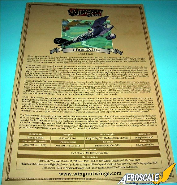
For years the only plastic kit of the Pfalz D.III / IIIa was the old Aurora 1/48 kit of the late 1950's. In the sixties there was the Renwal Aero-skin 1/72 injected kit. In the seventies it was a vacuform kit from Warbirds in 1/72. In the eighties it was the 1/72 Meikraft slush mold injected kit. Then the nineties saw a limited 1/24 release and Eduard finally releasing their 1/48 scale kit. As early as 1998 you couldnt throw a paint tin in a hobby shop without hitting some author doing a build up review of the 1/48 Bird of Prey for a magazine, club newsletter or internet posting. Now as interest in WWI aviation is rising so are the scales in which people are building. Roden is known for highly detailed tight fitting kits and it was no real surprise to most WWI aviation modeling fans that they released their 1/32 version of this famous machine. Then like lightning out of a clear blue sky Wingnut Wings announced their intent in 2009. And at the end of 2010 WNW 1/32 Pfalz D.IIIa kit was released. This is the review will focus on that fine kit.
What a review should do.
Now the aim of the single kit work up for review is not to rip apart a product. The focus should be to explain or answer questions about building the kit. What does the average builder know about the difference between a Pfalz D.III and a Pfalz D.IIIa ? In most cases the equipment in an open cockpit aircraft is foreign to the average model builder. Today, most modelers want to know, what is the tried and true method to be successful with a biplane kit. If your going to invest in a kit that costs as much as current kits do, your going to want to avoid pitfalls that will make your kit unattractive after its completed. In truth a half built kit is a nagging disappointment.
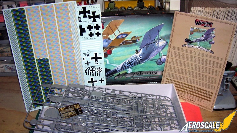
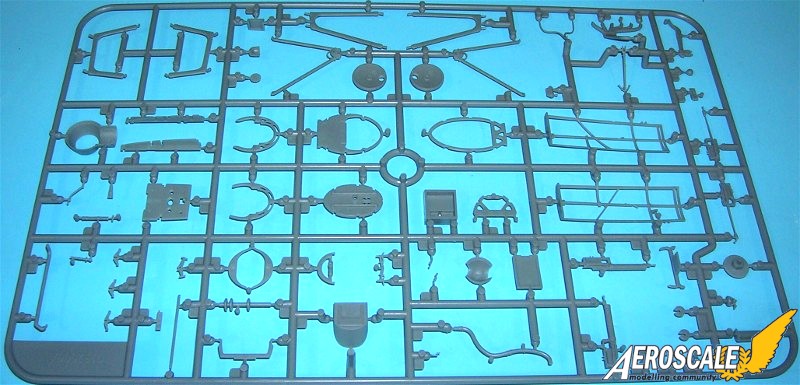
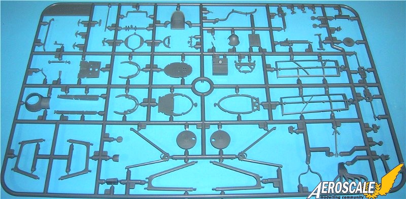
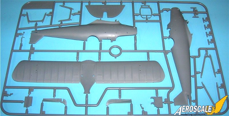
Kit Contents:
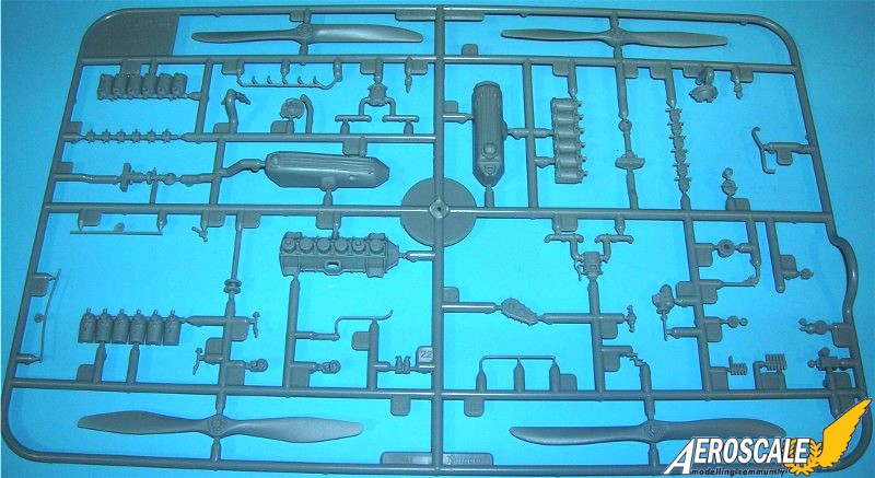
Plastic parts 149 pieces
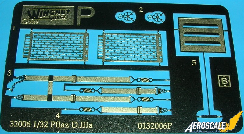
Photoetch 8 pieces
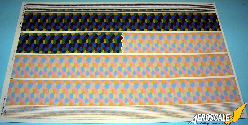
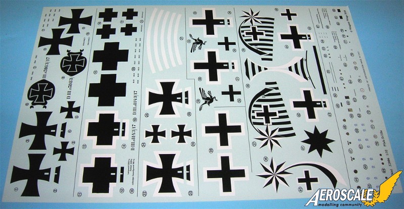
Lozenge for 1 aircraft (This is the very dark 5 colour type). Plus a bit more.
Decal profiles 5 aircraft
The build:
Step 1. Cockpit. We start with the fuselage former ( A 34, 36, 37, 43 & 44 ) at the mid-section of the cockpit. Add the fuel tank pressure, hand pump ( A 29 ). Please note the installation of fuselage former is inclined back about 2 degrees at the top. To the cockpit flooring ( A 32 ) add cables and a control column lock ( A 30 ) can be added to the control column base ( A 55 ) Note also that the rotating throttle on the control yoke head ( A 55 ) should be on the pilot's left. The machine gun triggers are in the middle of this yoke. Also add the rudder control bar ( A 14 & 31 ). The aileron actuation bar assembly ( A 2 & 7 ) connect to the bottom of the control column ( A 55 ) under the flooring.
Next this brings all of the previous sub assemblies together. Dont be afraid to open up the slots on the fuselage former slightly to accept the fuel tank locator stubs. Also I add the spout ( A 21 ). I used the kit fuel /air control panel ( A 5 ) and mounted it per kit instructions. The attempt at scratch-building a scale wiring control harness will be fragile but will pay greatly in the end. The water pump greaser ( A 22 ) should have a line leading forward in to the engine bay. The seat assembly ( A 11 & 27 ) is next. To do this area justice it is advisable that you add the PE lap and shoulder harness strap at this time See page 8 of the instructions.
Add the rear cockpit screen ( A 34 ). For the pilots left side of fuselage former add the starting magneto switch assembly ( A 15 & 56 ). To be absolutely correct one could add a wire switch to the circular area as there was a key that was attached by a small chain but would reach to the circular instrument. (Much like a key to the ignition of a modern car.) The Bosch starting magneto at the bottom of A 56 should have a bundle of ignition wires with a faded red insulation cover leading from the lower area of along the fuselage interior toward the forward area of the engine compartment. WNW did not supply an Spark Advance Lever or auxiliary throttle advance lever in this kit.
Step 2. Engine bay. Because of the fuselages high collar cowling around the cylinders not much of this area will be seen later. The exact placement of the engine bearer shelves ( A 38 & 40 ) in the fuselage formers ( A 13, 33, 41 & 42 ) is easy to deal with. They come together here is a subassembly. Note that the first former ( A 13 ) is first. The second former ( A 33 ) is angled slightly backward at the bottom and the third former ( A 41 ) is angled forward at the bottom. The oil tank ( A 50 ) sits on the engine shelf (A 40 ). The ammunition box assembly ( A 24, D 5, 11, 14, 15 ) sits on is the top of the main longerons. You can add eight R&R model detail nuts & bolts from Grandt Line to represent the motor mount items that would be apparent on the top face of the motor mount flanges. On the Albatros D types this was exposed and the handle was usually solid metal. On the Pfalz D. types this decompression bell was shrouded by a shell shaped covering. The handle was wood and unscrewed.
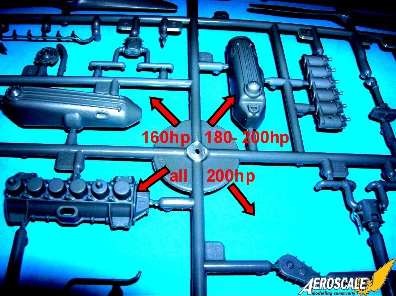
Step 3. Daimler Mercedes D.IIIaü 180hp and were generally known by the company as F-1466a. The upper portions of the original aircraft engine cylinders are covered by water jackets these are the color of black/blued gun metal. This kit shows the oil fillers / vent caps ( E 18 X 2 ), oil cycling tubes ( E 21 & 30 ) and the sparkplug support tubes ( E 15 X 2 ) for both side views of the engine.
The immediate visual difference in the early Mercedes D.III 160hp / D.IIIa 170hp (F-1466 )and its progeny the D.IIIaü 180hp (F-1466a) are in the rocker boxes above the cylinder jacket heads. On the early Mercedes D.III and D.IIIa motors the rocker springs are centered on the sides of the rocker box covers ( E 27 ). On the D.IIIaü motor the box covers are moved back so the rocker arms and springs are located on the forward leading edge of the same covers. The rest is below the cowling and not readily visible. The Mercedes D.III160hp was outclassed by 1917. In 1918 the Mercedes D.IIIaü 180hp was the standard engine in the Pfalz D.IIIa, Albatros late built D.V and all D.Va types starting in late 1917 and then the Fokker D.VII through 1918. Many, many Mercedes D. III and IIIa type motors were rebuilt to the D.IIIaü specs at the airparks as the war progressed. That is why some captured examples had motors with the i.d. designation of D.III 160hp cast into their crankcases. This has caused the misconception that the standard 160hp and 170 hp were used in 1918 at a time when they had become obsolete. Often these were referred to as 160hp over-compressed engines.
Step 4. Interior & guns. The tachometer ( decal 75 ) face on the Pfalz D. types appears to be upright in all cases. On other single seat types they were laid on their sides. Concerning the twin Spandau Maxim machine gun ( A 17 X 2 or A 45 X 2 ), .if you thinking about exposing the engine and adding photoetch gun jackets add them here. Also, confirmed by photographic evidence that none of the Pfalz D.III or D.IIIa types had a spade shaped cocking handle. These are popular items that some modelers like to add. The Pfalz fighters used T shaped handles ( but there should be two of these.) in the cockpit leading from the cocking levers on the right side of the gun breeches and worked via a linkage system. For further detail the left side of the left gun breach add an Auxiliary Throttle (push) Lever These items came as O ring or T handles. The Spark Advance Lever should be on the former near the starting magneto.
Here is a list of "other items that I will add to the cockpit.
a. 2 synchronizer cables from engine to gun breaches.
b. 2 Bowden cables from control column to the guns.
c. 2 rudder, 4 elevator cables.
d. brass conduit pipes for the electrical wiring from the instrument cluster on the pilot's right.
e. An auxiliary throttle advance lever.
F. Spark Advance Lever.
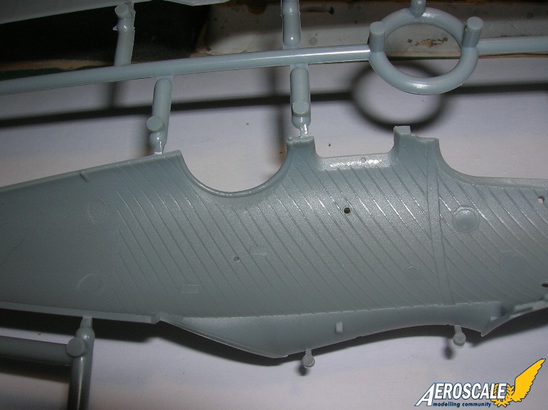
Step 5. Interior painting guide and uniting the fuselage halves. For the right fuselage half interior, make it easy on yourself, begin this project by familiarizing the areas for the internal structure of the fuselage halves ( D 6 & 7 ) and pre-drilling all rigging holes. Paint both fuselage halves ( D 6 & 7 ) interiors and the fuselage formers either:
A a dull aluminum.
or
B. a base color of Polly S dirty white, antique white, French beige or doped linen. This gives you a nice base for the plywood effect that you need to duplicate.
These items were manufactured separately and finished before adding to the fuselage shells. After these are thoroughly dry, spray the painted surfaces with a clear flat. Allow it to dry completely , then if you are doing a varnished wood interior begin with a wash of Testors (#1166) flat (orange) brown enamel always going parallel to the lath edges. Down the length if the fuselage. The resultant streaks will simulate the wood grain. Then dry brush just the frame work with the base colour. The colour variations that you create when doing this makes a great contrast to the inside wood lath. It is known that both methods were popular for sealing the interior shells of the Pfalz single seat fighters. Photographic evidence shows that both methods were used. There are even cases where the fuselage formers were varnished wood and the interior of the fuselage shells were aluminum doped.
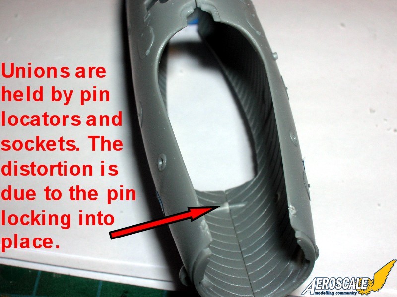
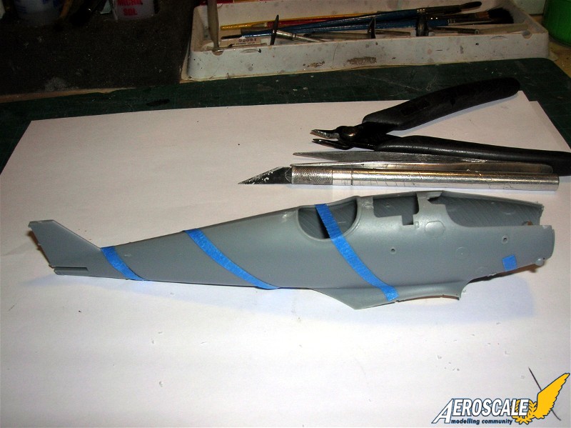
Now glue the fuselage halves ( D 6 & 7 ) together and allow to dry. To get the fuselage to close up you will have to clip off the decompression handle on the upper rear tower of the engine. This was removable anyway on the real machine (it unscrewed.)
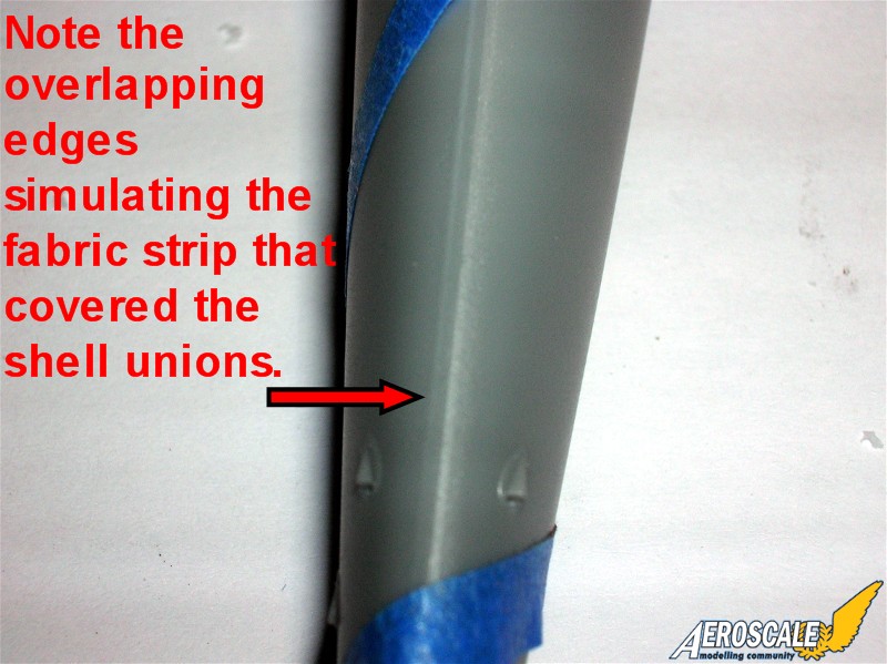
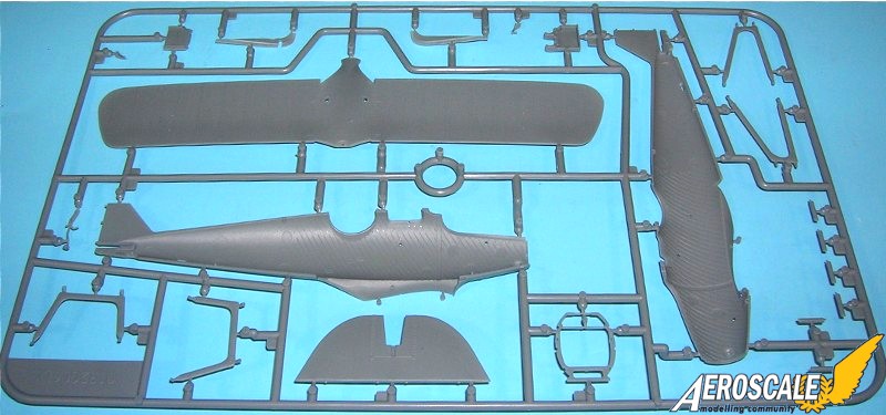
Step 6. Fuselage details and tailplane. Then erase all union seams. Add the rudder and horizontal tail unit assemblies. Careful sanding helps the horizontal tail unit ( D 3 ) fit properly. I use gap filling super glue (semi gelatin) to fill joint seams between all plastic parts joined to the fuselage. Note that canting control surfaces ( B 1 ) tends to give the piece a more natural look seen in period images of the real aircraft. The kit rigging control horns ( A 3 ) can be used per the instructions. Add the tail skid ( A 61 ).
Step 7. Engine cowls ( A 39 D12 & 13) and the empty Ammo belt chute on the pilots left Spandau ( D 10 ) are installed at this point.
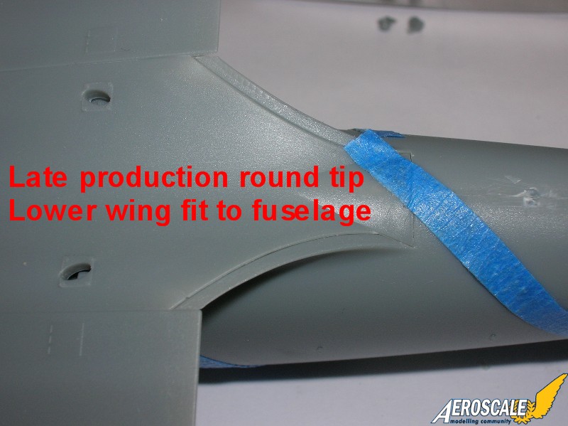
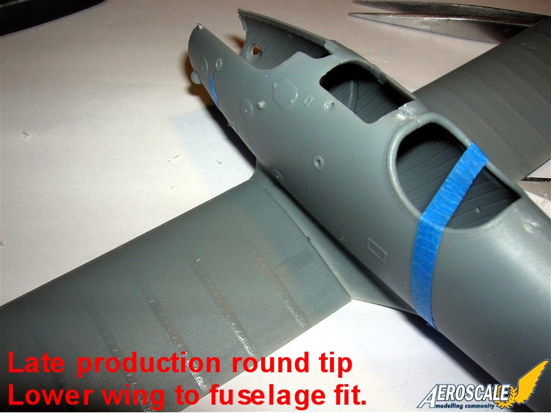
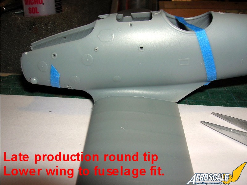
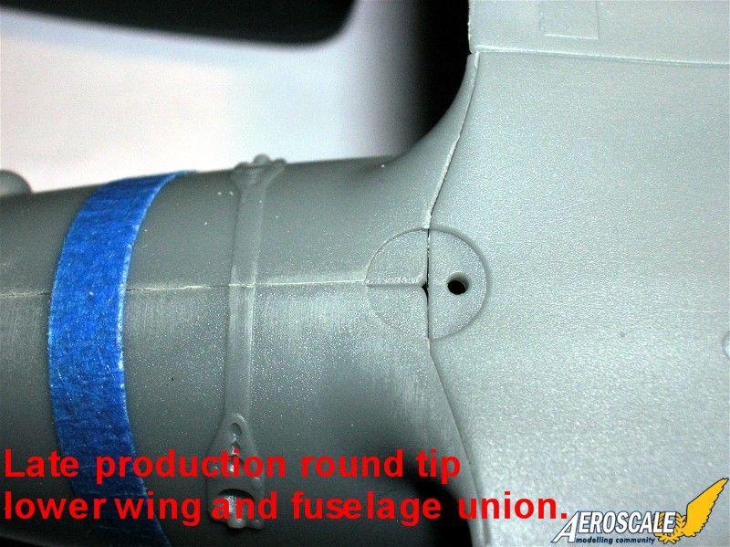
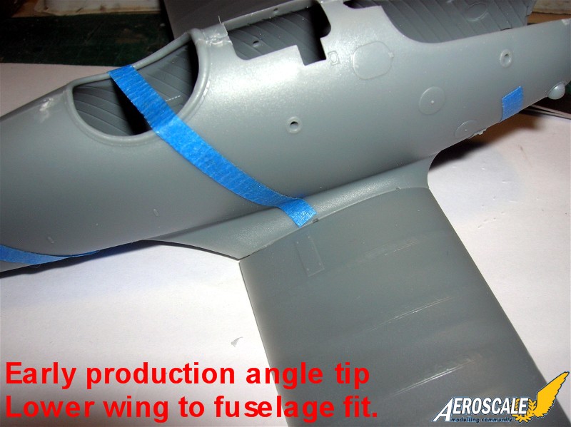
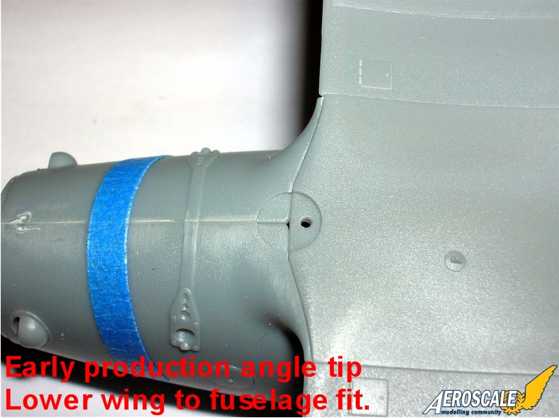
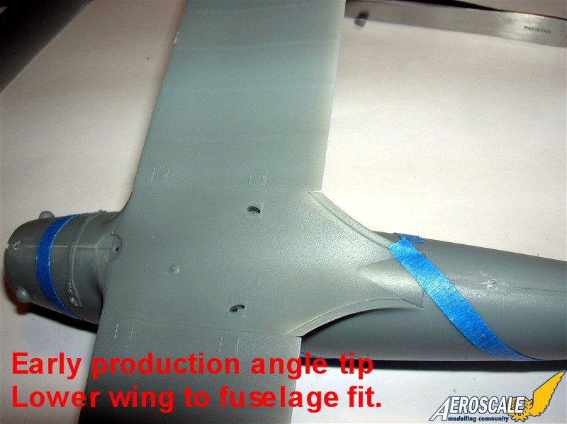
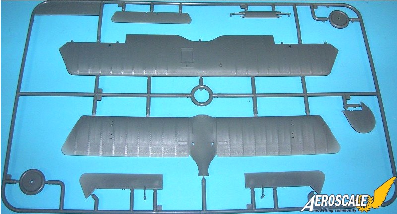
Step 8. Lower wings. Add the lower wing ( B 5 or D 9 ) at this time and had only minor sanding to finish. The fit is near perfect.
Step 9. Undercarriage / Landing gear. The weakest part of a Vee strut landing gear assembly in plastic is the side to side twist. In many kits this usually causes the plastic gear legs to eventually dislocate or break. But with the WNW kit I use the kit landing gear legs ( A 51 & 53 ) and the exposed axle ends ( B 2 ) with the appropriate diameter blackened brass rod. I use upholstery thread to wrap around the lower legs of the landing gear with the axle, to simulate the bungee shock chords. This looks like the original and actually secures the axle in place with one drop of cyanoacrylate glue. Finish any rigging now.
Step 10. Struts. Note if the cabane ( A 46 or 47 or D 1 & 2 ) or wing struts ( A 57 & 58 or D 16 & 17 ) ends enter the wing at an angle drill your insert holes accordingly.
Step 11. Exhaust pipes ( D 8 X 6 )or engine exhaust manifold (A 60 ). The common exhaust is seen here but there were several manufacturers.
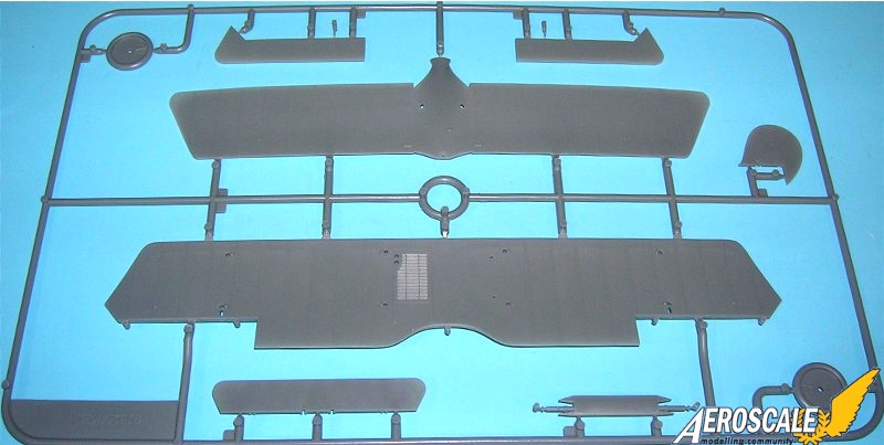
Step 12. Upper Wings and ailerons. Top wing ( B 4, 7 & 8 ) details show the radiator filler tower ( A 54 ). In most cases a shutter system was employed on the D.III and D.IIIa airframes. This was to either dissipate or retain heat in the radiator. Depending on the weather conditions during a given patrol or flight.
Now we bring the fuselage and wings together. It should be noted that most circular engine access panels need to be flush to the surface but not completely erased. For the top wing ( B 4 ) I generally paint or apply lozenge to the undersurface of the top wing and the upper surface of the lower wing ( B5 or D 9 ) at this point before assembly and rigging. It depends on which one is applicable to the machine you are building. Otherwise all other parts I add as per instructions. Next is the installation of the fuel lines ( A 59 ) for the reserve / gravity tank. See the comments section on this tank.
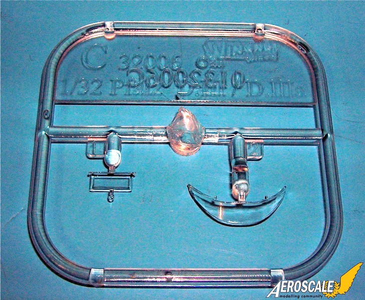
Step 13. Final assembly propeller(s) and spinner. I personally like scratch- building my kit propellers from light and dark woods. I have also learned to paint the laminations with convincing effect. ( A 28, E 23, 24 & 46). . Most of the Pfalz fighters were equipped with the light and dark laminated propellers. Carefully check the aircraft profile your modeling to choose the right propeller. WNW offers three possibilities with this kit. The company determined the paddle profile of the propeller (it was their trade mark) while the engine application determined its pitch and length. So all three profiles could be seen on the Pfalz D.IIIa,They all had the same pitch because of the factorys installation of the Mercedes D IIIaü 180hp motor. Assembles last water / coolant pipe ( A 1 ) After the final clear coat of your model dries thoroughly attach your choice of windscreen ( C 1 or 2 ) with white glue.
Step 14. Rigging diagram needs to be referenced repeatedly during the steps where you unite the wings to the fuselage..
Kit decals:
A. D.5983/17, Oblt. Hans Joachim Buddecke, Jasta 30 February 1918 (13 victories).
B. D.8143/17, Ltn Walter Ewers, jasta 77b, April 1917 (8 victories).
C. D.xxxx/17, Ltn. Max Hitschler, Jasta 18, late 1917.
D. D.xx21/17, Uffz. (later Vzfw) Max Holtzem, Jasta 16b, April - June 1918. (2 victories).Around the turn of the century the comet was seen as a departed soul en route to heaven. Holtzem's mother had died when he was nine years old and he had the comet painted on all his Jasta 16b aircraft to denote her spirit as his 'Guardian Angel.' As an aside I would like to note that Max Holtzem immigrated to the USA after WWI and settled in Whittier Beach California. During WWII he worked as a quality control inspector on the P-51 Mustang assembly line. Max Holtzem later befriended Dr. J. J. Parks President of the Lafayette Foundation and shared his wartime experiences.
E. D.xxxx/17, Ltn. hans Müller, Jasta 18 April 1918 (12 victories).
kit lozenge camouflage decals
There is a bit of joy with the lozenge (Flugzeugstoff) decals in these kits. Both the upper surface and under surface colours 5 colour are a reasonable attempt to copy the known colour dyes for the intermediate version. The kit recommended lozenge application (chordwise) is accurate in the instructions. I am told the decals behave well with Microset & Microsol, not so great with Solvaset. Their website actually recommends against sols & sets. Pfalz used the "Very dark" five color printed fabric rib tapes, To get from the WNW version of the "Intermediate" to the original "Very Dark" fabrics there should be a dark over spray / texture to gray down the intensity of the WNW decals.
References:
Colors by Greg VanWyngarden, Over the Front Journal Vol 2 #4,Pp.371-5, 1987.
Fliegertruppe Nr. 2 by A. E. Ferko, private publishing. See UTD Special Collections.
German Army Air Service in WWI by R. Rimell, Osprey Vintage Warbirds #2, 1985.
German Fighter Units June 1917-1918 by A. Imrie, Osprey, Airwar #17,1978.
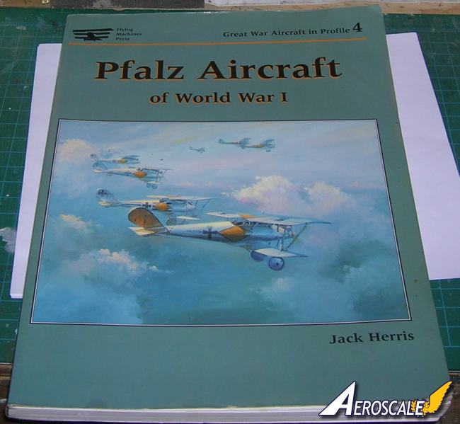
Pfalz Aircraft of World War I by Jack Herris, Flying Machines Press, 2001.
Pfalz by P. Grosz & E. Krüger, WWI Aero Pub. inc. 1964.
Pfalz D.III by R. Rimell, Datafile WWI a/c Part 1, Windsock, Albatros Pub. Ltd. Pp.20-31, 1990.
Pfalz D.III by P. Gray, Profile Pub. #43, 1965.
Pfalz Scout Aces of World War I by Greg VanWyngarden Osprey pub. #71, 2006.
Pfalz D.III Technical evaluation by Flight Cross & Cockade USA Vol.1 #4, Pp. 29-53,1960.
Pfalz D.III 1370/17 evaluation by Flight Cross & Cockade USA Vol. 2 #3 1961.
Pfalz D.IIIa by P. Grosz, Windsock Datafile #21, Albatros Pub. Ltd. 1989.
Pfalz D.III by P. Grosz, Windsock Datafile #107, Albatros Pub. Ltd. 2004.
Pictorial History of the German Army Air Service by A. Imrie, Ian Allen Pub. 1971.
Scale Model Aircraft in Plastic Card by H. Woodman, Model & Allied Pub., 1975.
Spandau Machine Gun by David Watts, WWI Aero,1998.
World War One in Plastic by Brad Hansen, Great Auk Pub. 1979.
Comments from wnw, Richard Alexander
. . .The (gravity feed) fuel tank was on the inside of the Pfalz D.III and D.IIIa upper wing. It was covered with the ply that skinned the center section and was not visible on the upper surface of the wing (other than the faired in filler tube/cap protruding through the wing).
I don't know exactly when the myth of it being a detail visible on the
outside of the wing began, but it appears to have been started by an early
draftsman misinterpreting the Pfalz D.III drawings in the Flight capture
report. In the original Flight report the internal wing tank was drawn
with dotted lines to indicate that it was an internal detail.
Additionally the wing tank is not visible in any photo of a Pfalz D.III or
D.IIIa that I have ever seen (other than certain crash photos where it has
fallen out of course).
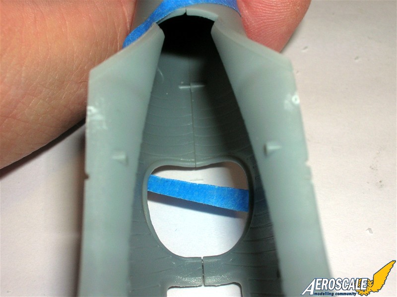
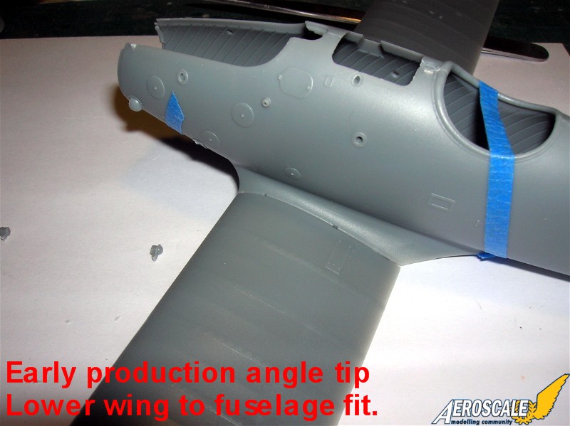
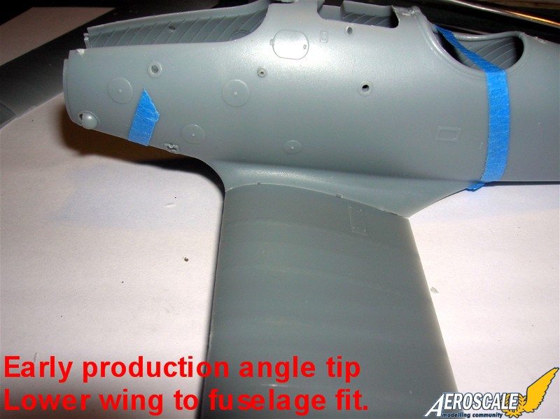
The lower wing root panel which is 'missing' is a reinforced walk strip presumably intended for a mechanic to stand on while he makes final engine etc adjustments before flight. These don't appear to be on every airframe and when they are, they're not a standard size. It was not possible to confirm if these were on any of our colour schemes, let alone what shape they would be if they were. A pretty simple thing to add if you feel your model needs it (check the reference photos in our instructions and on the website for the shapes and sizes).
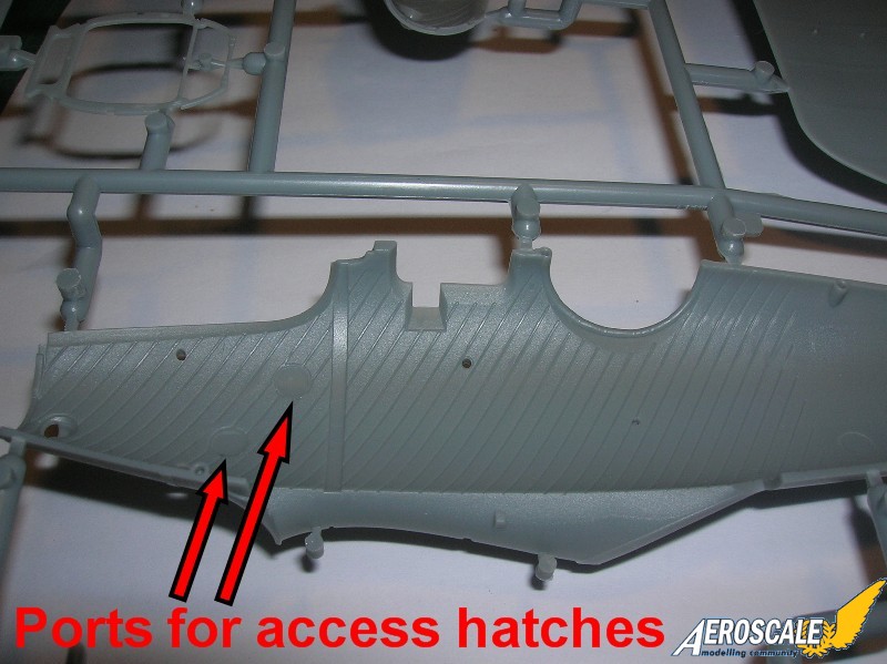
The 2 smaller hatches on the upper surface of both lower wings are covers
for the point where the aileron control cables are connected to the cables
coming from the control column. These hatches are hinged at the front and held down by 2 turn buttons at the rear.
The wing attachment lugs are covered by the 4 smaller hatches under the
lower wing. These were also hinged at the front and held down (up?) by a
single turn button.
I hope this clears things up a little.
Regards
Richard"
When contacting manufacturers and publishers please mention you saw this review at AEROSCALE
SUMMARY
Highs: Excellent details a hansome addition to any display. Fit is almost perfect.Lows: Some separate instrument gauge bezels would have been great.Verdict: An beautiful kit that deserves a place on the display shelf.
Our Thanks to Wingnut Wings! This item was provided by them for the purpose of having it reviewed on this KitMaker Network site. If you would like your kit, book, or product reviewed, please contact us.
About Stephen T. Lawson (JackFlash) FROM: COLORADO, UNITED STATES
I was building Off topic jet age kits at the age of 7. I remember building my first WWI kit way back in 1964-5 at the age of 8-9. Hundreds of 1/72 scale Revell and Airfix kits later my eyes started to change and I wanted to do more detail. With the advent of DML / Dragon and Eduard I sold off my ...
Great review Stephen
This one is high on my * I wanna* list and once I get caught up with some other projects I might well order it. Your review has whetted my appetite as I sit and wait for Parcelforce to process my Roland and advise me it's ready for collection upon paying taxes and their *administration fee*.
Now if I might ask something? The new lozenge for this kit, how does it look in comparison with their Lozenge from the LVG which was a little dotty when viewed close up? Presuming of course you have access to A LVG
Keith
Part of my review will be to add a comparison of the WNW and the Doug Baumann lozenge. There are some questions in my mind about both versions. I will try to make the WNW sets work on my up coming build. More in the near future.
Nice additions Stephen, I see WNWs attention to detail in this kit is as good as the Roland. Clever ejector pin positioning I have to say *checked the Roli and its the same in the inspection hatches
Guess this one is raised to next on the list for me unless WNW decide to release the DVII of course
Kb
Thanks Keith,
Now for some wing lozenge application notes:
1. On the lower wing panels the application went chordqwise from the wing root to the tip.
2. On the upper wing the center section was covered seperately chordwise.
3. On the upper wing panels were also covered chordwise from their wing root out to the tip.
4. On the ailerons they were covered separately spanwise.
5. Rib tapes were strips of 5 colour upper surface loz.
Historian Dan San Abbott states
"There were a considerable number of Pfalz D.IIIa in the January 1918 order for 340 D.IIIa machines, serial numbers D.8000/17 to D8339/17 that were covered with the intermediate dark 5 color printed fabric on the upper surfaces of both wings, elevator and rudder.
The ribs on the wings, ailerons, elevator and rudder were taped with cut strips of the five color intermediate dark pattern approximately 25 mm wide. The photo on page 27 is Pfalz D.IIIa 8052/17 is covered with five color fabric intermediate dark pattern, with matching rib tapes. . .The 1918 order for 120 Pfalz D.IIIa serial numbers D1250/18 to 1369/18 were covered on the upper surface the same way, however, some had the lower surfaces of the wings and elevator with plain unprinted unbleached linen fabric. The under surfaces were were over painted lt. blue, Pfalz D.IIIa 1284/18 is an example. See photos on page 20 of the Pfalz D.IIIa Datafile 21.. . .
I believe the center-section of the upper wing was covered with fabric. . . .On page 20, these two photos I think were taken at the Pfalz Flugzeugwerke, these photos are of Pfalz D.IIIa 1284/18 and this machine is unfinished. The fuselage and rudder crosses lack the white borders and the spinner has not been installed. There is a man in the bottom photo in a suit, white shirt and tie in the back ground. the strut end fitting are probably a black japaned finish. This was a fairly common method of finishing metal parts.
On page 27, is operational Pfalz D.IIIa 8052/17, with a dark band and a white E. The lower wing shows the five color fabric, the fuselage, struts were, wheel covers and axle-bar were finished in aluminum paint/dope. The upper wing faintly shows a lozenge, just forward of the trailing edge cut out, this is on on the plywood area of the upper wing center section."


Comments