The Albatros D.V was an attempt to lighten the Albatros D.III design. The fuselage was given an oval cross-section. The wings profile is identical to the D.III , but had aileron cables routed through the upper wing to shrouded actuating cranks. The motor was the 170 hp Mercedes D IIIa. In the first three months of operation the Albatros D.V was plagued with several fatal crashes due to the unmodified wings being matched with what turned out to be a heavier airframe overall. The quick fix was to add bracing wires and a small auxiliary strut to the lower front leg of the Vee struts. The real fix didnt come appreciably until the lower wing spar was itself strengthened and stabilzer wires were added at the factory level.
The Kit
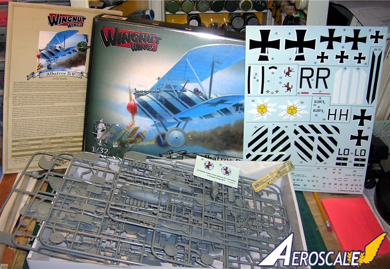
One of Wingnut Wings. com (WNW) most anticipated kits to date has been the release of their 1:32 Albatros D.V & D.Va kits. We begin with their kit #32009 to be released in mid March 2010. This new molding is a sound move. As the Albatros D. types were the backbone of the German Air Service (Luftstreitkrafte) there are literally hundreds of colour schemes that can be employed. WNW has wisely assessed that this kit will have longevity. Begin by washing all parts in a warm water and antibacterial soap mix. Next pre-drill all strut and rigging locator holes. Check your references.
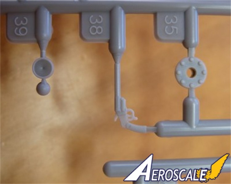
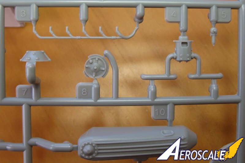
Step 1.) First, the cockpit structure assembly (PP A 11, 19, 21, 23 & D 12 X 2 ) creates a manageable sub-assembly that is supposed to fit into the fuselage shells. The simulated support rods ( D 12 X 2 ) of the seat cradle assembly dont seem to extend deeply enough in to the plastic rear cockpit wall ( PP A 19 ) or the forward supports (PP A 23.) So I added the individual parts first not as a completed unit. Minor adjustments allowed everything to fit well. The fuel /air control panel (PP A 15, 39 ) is mounted to the fuselage right side (PP F 10 ) per instructions. Attached to the top of the fuel /air control panel (PP A 15, 39 ) is the fuel quantity gauge. The tube for the fuel tank pressure-hand pump (PP A 16 ) has the handle molded on as well. The same goes for the water pump greaser- tube (PP ) and its handle. On the rear machine gun brace (PP A 2, 10) paint and add the instrument face. Note, the tachometer face was laid on its side for ease of reading in-flight and was a normal practice of its time. Cables and a lock can be added to the control column (PP A 6, 45.) For the D.V variant a circular pivot pulley is impaled centrally on the forward leg of the control column (PP A 45 ) at its mid point. This was the pivot point for the aileron actuation and the cables extend upward into the top wing. When all cockpit items are in place I carefully add fine wire for the rudder and elevator control cables.
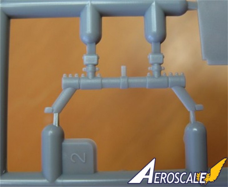
Step 2.) In the future I may modify the ammunition box (PP A 18, 42 ) The feed chutes on the ammunition box (PP A 18) needs a single line scribed across their face to denote an access cover. Next a reserve /main fuel tank assembly (PP A 13, 17 & F 14). These will rest behind the engine cylinders against forward cockpit bulkhead(PP A 22 )& engine bearer shelves (PP A 1 & 8 ). This tank should have two filler spouts and a fuel pump housing directly on top of the tank. See step 5.
Step 3.) Now comes the build up of the early 170hp Mercedes D. IIIa six cylinder inline engine (PP E 4 - 22, 30, 32 & F 13 ).
Step 4.) On the late 170hp & all examples of the 180hp Mercedes D. IIIaü six cylinder inline engine ( PP E 4, 8, 11 - 22, 25 - 32 & F 16 ). Erasing the center line seam and opening up the gaps between the cylinders is needed. Depending on your adherence to the exact placement of the engine bearer shelves (PP A 1 & 8 ) in relation to the forward cockpit bulkhead (PP A 23 ). Next, add R&R model detail nuts from Grandt Line to represent the motor mount nuts & bolts that would be apparent on the top face of the flanges. The upper portions of the cylinders are covered by water jackets and are the color of blued gun metal. The early D.V types saw the installation of the Mercedes D.IIIa 170hp. It has a small air pump in front of the #1 cylinder. The rocker assembly ( PP E 6 ) is representative of the 170hp. The immediate visual difference in the early Mercedes 160 hp D.III / 170 hp D.IIIa and its progeny the 180hp D.IIIaü is the rocker springs exposed above the cylinder jacket heads (PP E 27). On the D.III and early D.IIIa motors the rocker springs are centered on the sides of the rocker box covers. On the late 170hp D.IIIa & the 180hp D.IIIaü motor the springs are located on the forward leading edge of the same covers. The rest is below the cowling and not readily visible. Several good manufacturers note the difference and have two distinct castings. Wingnut Wings has followed suit. The Mercedes 160hp was outclassed by 1917. The Mercedes D.IIIaü 180hp was the standard engine in both of the Albatros D.V & Va starting in late 1917 through 1918. Many, many D. III and IIIa type motors were rebuilt to the D.IIIaü specs at the airparks as the war progressed. That is why some captured examples had motors with the i.d. designation of 160hp D.III cast into their crankcases. This has caused the misconception that the standard 160hp and 170 hp were used in 1918 at a time when they had become obsolete.
As mentioned if you are doing a late production D.V version you will need to duplicate the Mercedes D.IIIaü 180hp engine. Primarily the water pump on the D.IIIaü is located directly behind the oil pump and some of the external plumbing is routed differently. Also it has a thicker stand up air pump in front of the #1 cylinder. Add fine wire painted black or white to make spark plug wires.
Step 5.) Is the assembly of the engine compartment support station and formers (PP A 27-30), engine bearer shelves PP A 1 & 8), Oil tank PP A 25 & 30) and the chosen engine assemble from steps 3 or 4.
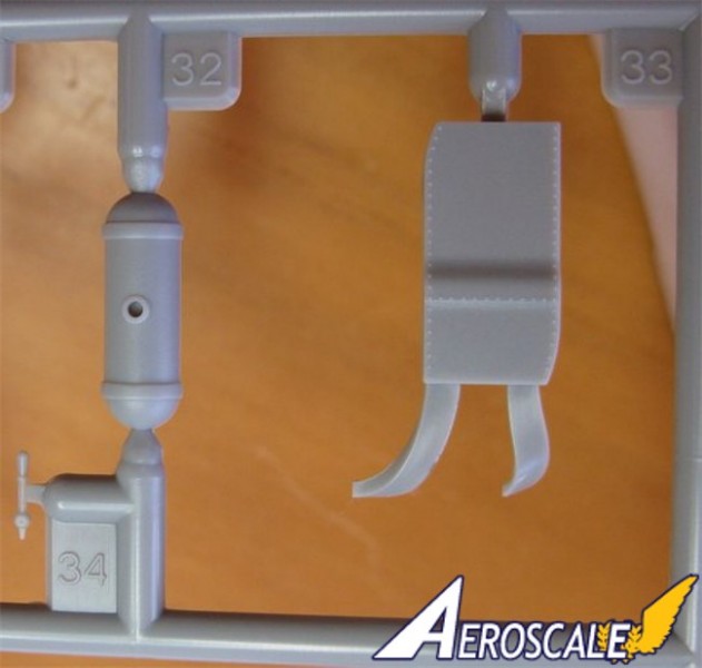
Step 6.) PP A 20 contains the magneto switch (circular instrument) and the spark control handle (PP A 34 ) that the instructions tell you to fold upwards. Add a short section of wire to the bottom of the spark control handle leading forward under the starting magneto assembly (PP A 20 & 34 ) and disappearing into the forward cockpit bulkhead assembly. To be absolutely correct WNW added a circular area in relief and there is representation of a key that was attached to the fuselage by a small chain but would reach to the circular instrument. ( Much like a key to the ignition of a modern car. ) The Bosch starting magneto (PP A 5 ) is a little thick if your using the bracket so I cut away 1/3 of its back side thickness. There should be a bundle of ignition wires with a faded red insulation cover leading from the lower area of the spark control box ( PP A 20 ) along the fuselage interior behind the starting magneto (PP A 5 ) to the forward cockpit bulkhead.
Step 7.) Concerning the twin Spandau Maxim machine guns, you may want to alter the cocking handle assembly (PE d 5 x 2 )by modifying a simple lever with a rounded knob protruding at a 90 degree angle to the right. It is confirmed by photographic evidence that none of the D.V types had the 1918 spade shaped cocking handle and no picture of a D.Va exists with them either. The Albatros fighters used "T" shaped cocking handles in the cockpit leading from the cocking levers on the right side of the gun breeches and worked via a linkage system. If you can get a set of 1:48 scale rear gun sights the are perfect for the 1:32 scale guns.
". . .Also, the gun support bar is slightly to long. I remedied this by filing the tabs that glue into the fuselage slots. I had to remove about half the tab on each side. This might be due to a bit of paint in the slots. I thought I got it out, but I might not have gotten it all. So I can't fault the kit. Beware the tolerances. . ."(Info via Aeroscale member C. Althaus.)
When considering the tail skid try to see this piece under stress by adding a .020 shim behind the bungee chords touching the skid housings and painting the shim and the chord area the same color. Join the fuselage halves (PP F 5 & 10 ). Careful sanding helps the horizontal tail unit (PP B 1,2 & 7 ) fit properly. I used gap filling super glue (semi gelatin) to fill joint seams between all plastic parts joined to the fuselage.
Step 8.) Don't add your choice of windscreen yet. But go ahead with the engine cowlings (PP F 2 & 3 ) and the flare cartridges applicable to your build. I would do as recommended and leave the engine cowlings off for display. But that how I usually do my inlined engines in 1:32.
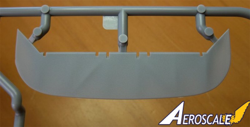
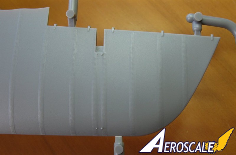
Step 9.) Note also, the covers on the lower wings (PP B 3 & 4 ) are for the Albatros D.Va variant not the D.V . These were the upper surface access covers for the aileron pulleys. So the instructions rightly advise to scrap them off.
Step 10.) Usually I would replace the kit struts (PP A 3 & 4, D 8 X 2 ) with cut and shape brass rod of an appropriate diameter for longevity. Otherwise all other kit parts I add as per instructions.
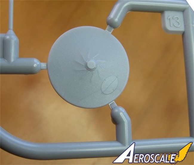
Step 11.) Add the radiator shutter assembly after you have painted or applied lozenge decal to the under surface of the top wing. I generally paint the undersurface of the top wing and the upper surface of the lower wing at this point before assembly and rigging. The radiator facades (PP F 6 -9) are identified by aircraft profile / colour scheme. It depends on which one is applicable to the machine you are building.
Step 12.) Top wing and aileron facade applications include. Shroud guide (PP A 48 , PE 1) for the aileron cables.
Step 13.) Attaching the top wing. Can be a very easy prospect. If you have concerns just use a childs set of Lego blocks. Everything will dry plumb and square. Note location of the water pipes in this and the following steps.
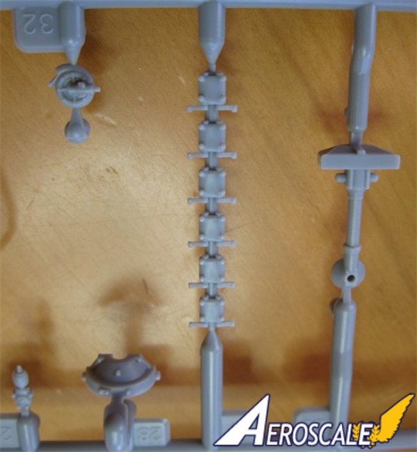
Step 14.) The weakest part of a Veestrut landing gear assembly in plastic is the side to side twist. This causes the gear legs to fatigue, bend and or break. I would consider replacing the landing gear legs (PP A 40 & 41 ) and the axle spreader bar (PP A 24 )ends with the appropriate diameter brass rod. Check references for correct height of your scratchbuilt landing gear legs. I will usually use upholstery thread to wrap around the lower legs of the landing gear with the axle in place to simulate the bungee shock chords. This looks like the original and actually secures the axle in place. Also a drop of Cynoacrylate here on the thread adds a great amount of strength. WNW has this molded in place.
Step 15.) I personally like scratchbuilding my kit propellers from light and dark woods. I have also learned to paint the laminations with convincing effect. Most Albatros fighters were equipped with the light and dark laminated propellers. Carefully check the aircraft profile your modeling to choose the right propeller. The D.V and D.Va both used three types of propellers that have been offered with in the kit. The propeller parent company determined the paddle profile of the propeller (it was their trademark) while the engine application determined its pitch and length. So all three profiles could be seen on either the D.V or the D.Va. But with different pitches because of the different horse power of the installed motor. The oppossing page is also labels step 15 and details rigging paths.
Step 16.) The seam on the exhaust horn (PP A. 38) can be erased and the open end drilled out partially to simulate the original.
After final clear coating of your model attach your windscreen.
Kit Decals for #32009 markings
A. Albatros D.V 2034/17 as flown by Haupt. Eudard Ritter von Schleich Cmdr of Jasta 21 Sept. 1917. Schleich was nicknamed "The Black Knight" and was a native of Bavaria.
B. Albatros D.V 2078/17 as flown by Ltn. sur Zee Ottomar Hagenmüller of MFJ I. He was KIA 5 Dec. 1917.
C. Albatros D.V serial unknown as flown by Ltn. Otto Kissenberth of Jasta 16b mid - 1917.
D. Albatros D.V serial unknown as flown by Ltn. Fritz Rumey of Jasta 5 in early 1917.
E. Albatros D.V serial unknown as flown by Oblt. Ernst Udet of Jasta 37.
Albatros D.V serial #s
D.1000/17 - 1199/17, 200 airframes ordered April 1917, Johannistahl.
D.1962/17 - 2361/17, 400 airframes ordered May 1917, Johannistahl.
D.4403/17 - 4702/17, 300 airframes ordered in July 1917, Johannistahl.
Total = 900 airframes.
Listed References
Albatros D.V/Va, War Horse of the Luftstreitkrafte by S.T. Lawson, SAM Pub. Model Aircraft Monthly, Vol 1 #2 , Pp.54-59.2002
Albatros D.V/Va, Part II, The Spoils of War by S.T. Lawson.
Albatros Aces by Franks 2000, Osprey pub.#33.
Albatros Scouts Described by Chas Schaedel, 1971 Kookaburra Tech. Pub.
Albatros Fighters Datafile Special by Ray Rimell, 1991 Albatros Pub. Ltd.
Albatros D.V by Peter Gray, 1965 Profile Pub.#9.
Albatros D.V & D.Va Described and Drawn by Ian Stair,1972 Scale Models.
Albatros D.Va German Fighter of WWI by Robert Mikesh, Smithsonian Inst. Press.
Lafayette Foundation Archive. Denver CO. USA.
Scratchbuilding Techniques by Alan Clark, 1990 Scale Models Int. Pp174-5.
Scratchbuilt Albatros D.Va by Alan Clark,1990 Scale Models Int. Pp.491-495.
Spandau Machine Gun by David Watts,1998 WWI Aero.
'The Last Albatros' by Colin Owers 1988 Aviation News Pp.216-221.
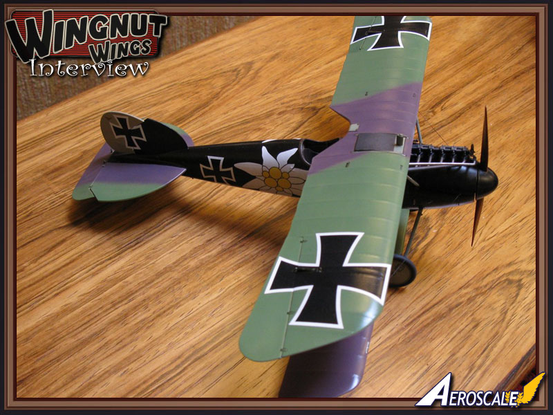
My sincere thanks to James Fahey for his contribution to this review. The sprue and model images with the wooden table top backgrounds are his.
Also please mention the Aeroscale review when contacting Wingnut Wings
Highs: Excellent details & fit looks good. Long over due subject in 1:32Lows: Small error in identifying the engines.Verdict: Top drawer kit that will become a standard in this scale.
Our Thanks to Wingnut Wings! This item was provided by them for the purpose of having it reviewed on this KitMaker Network site. If you would like your kit, book, or product reviewed, please contact us.
About Stephen T. Lawson (JackFlash) FROM: COLORADO, UNITED STATES
I was building Off topic jet age kits at the age of 7. I remember building my first WWI kit way back in 1964-5 at the age of 8-9. Hundreds of 1/72 scale Revell and Airfix kits later my eyes started to change and I wanted to do more detail. With the advent of DML / Dragon and Eduard I sold off my ...
Hi again
Well, my D.V arrived today!
It's my first chance to see a Wingnut's kit "in the flesh", so to speak... Wow! It's fantastic!
Huge thanks once again to James!
All the best
Rowan
Looking at the condition the box arrived in makes me think Wingnut Wings probably pack their orders rather better than I did Rowan. I was trying to minimise postage costs for you, even then it was about $23 NZ which is how many GBP? About 9 pounds? Maybe WNW can get cheaper postage from NZ Post than over the counter. Hope everything is OK inside.
Cheers
James
puts me stripey sweater and lone ranger mask, grabs me swag bag and sets out for Rowan's house.......waits in his shed till the house is in darkness and ...............
wrong house....damn this TomTom
Keith
Hi Stephen
It look's like Keith's gone for the D.Va instead. With a pair of them to keep him busy, my D.V might be safe... But I'd better not take any chances - I'll get to work on it once my '190 is finished.
All the best
Rowan
I tell you it was Bl**dy cold in that shed....
Yes I went for a pair of DVa's but I have hints spread for a pup and DV....see how it goes. Interesting thing I noted though on the DVa instructions, the parts are there to make an earlier DIII Engine too.
Now time to play the waiting game
K


Comments