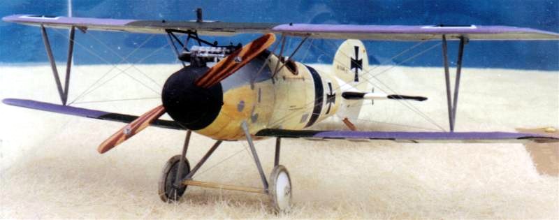
One of Eduard's best selling kits to date has been the early manufacture of their 1/48 Albatros D.V/ Va kits. #8013, 8019 & 8030. Beginning with their premier Pfalz D.III (kit #8005) Eduard started a more sophisticated manufacturing practice that improved the overall detail, appearance and quality of their kits. This change moved Eduard away from limited-run slush mold manufacturing to computer aided/controlled high pressure injection molding. Their LTM process of molding kits brought them into the leading edge of model manufacturing.
At the beginning of 2002 we saw that Eduard released their * 'neu' mold of the Albatros D.V kits (Feb, #8109 and in March #8110 Profipack) at www.eduard..cz . The new process allowed for a finer more exacting detail to be included in the overall plastic mold surface. It easily competes with any of the Tamigawa companies processes. Some people groused about the redo even if it were a new molding. Eduard explained that the attempt was to bring up the Alb. D.V kit to the same status as current production examples of other kits. This is a sound move. As the Albatros D. types were the backbone of the German Air Service (Luftstreitkrafte) there are literally hundreds of colour schemes that can be employed. Eduard has wisely assessed that this kit would have longevity. Here after seven years and at least 5 appearances since then ( #1111, 1107, 1124, 1136 & 1136X ) The mold has seemed to prove itself well over time. It is the buildup for the Eduard #8112 "Profipack version that we will discuss here.
Most of you will remember that Eduard was going to retire the Profipack title with their premier issue of the Bristol F 2b. Yet we see that it now has come back strong to Eduards advantage.
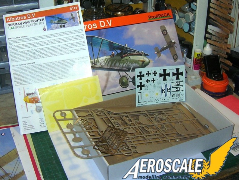
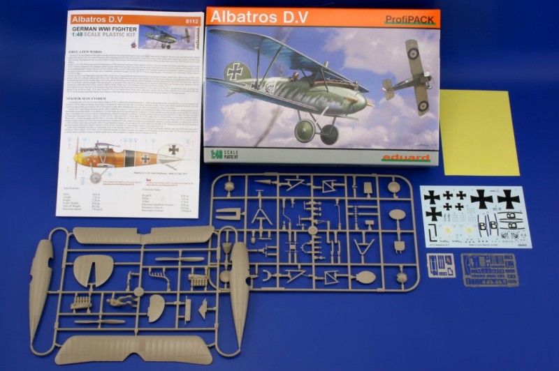
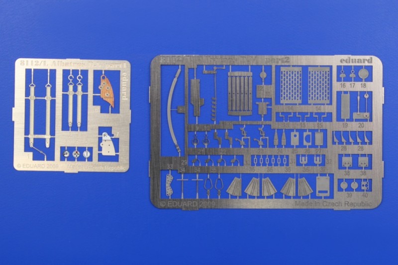
Box contents
60 Plastic parts
Color photo-etched parts
5 camouflage variants
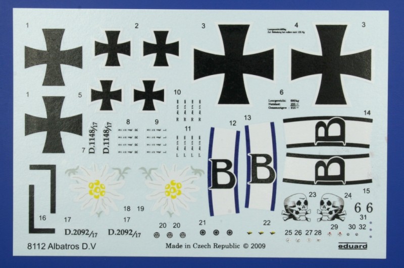
Decal sheet
Express mask
The build
Page 1. This Eduards usual multilingual history page.
Page 2. Is the general instructions, parts and paints maps.
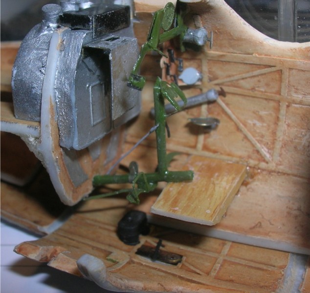
Page 3.) First, the cockpit structure assembly (PP B 6,12, 19,31 & 36) creates a manageable sub-assembly that is supposed to fit into the fuselage shells. The simulated support rods of the seat cradle dont seem to extend deeply enough in to the plastic rear cockpit wall (PP b36) or the forward supports (PP B 12.) So I added the individual parts first not as a completed unit. Minor adjustments allowed everything to fit well. In the future I will modify the ammunition box (PP B 37) to fit higher than the recommended position on the forward cockpit wall (PP B 35.) If you dont the Ammunition feed chutes dont seem to quite reach the Spandau inlet ports. This means grinding down the shoulders of the ammunition box by about 1/32 of an inch. The feed chutes on the ammunition box (PP B 37) needs a single line scribed across its face to denote an access cover. Shoulder and lap straps (PE 1 & 2 X 2 ) and their attachments (PE 16 & 17 ) may be attached as recommended.
The fuel /air control panel (PE 6 & 7 or PP B 11) is mounted to the fuselage right side (PP A 2) per instructions. In this Profipack issue of the kit the panel has the switches (PE 15 x 4) as separate items. Some of the other improvements in this new mold are; Eduard provided the air pressure gauge to be located at the apex of fuel & air panel (PE6 & 7 ) . The tube for the fuel tank pressure-hand pump (PP B 16) has the handle molded on as well. The same goes for the water pump greaser- tube (PP B 15) and its handle. (see page 4)
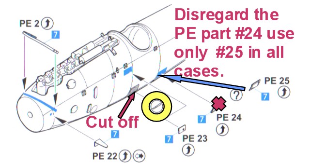
Page 4.) On the rear machine gun brace (PP B 20) I add a slice of sprue to the rear of the tachometer to represent a backing cup. Then when dry paint and add the instrument face. Note, the tachometer was laid on its side for ease of reading in-flight and was a normal practice of its time. Attached to PE6 & 7 assembly there is a fuel quantity gauge ( PE 3 & 25 ).
Cables and a lock can be added to the control column (PP B 18.)Add the kit control yoke (PP B 22) to the column. And add a small lever to the pilots left handle for an auxiliary throttle lever. For the D.V variant a circular pivot pulley (PP B 28) is impaled centrally on the forward leg of the control column (PP B 18) at its mid point. This was the pivot point for the aileron actuation and the cables extend upward into the top wing. When all cockpit items are in place I carefully add fine wire for the rudder and elevator control cables.
With the attachment of the spark control box (PE 20 or PP B 23) one may want to erase the
detail on the plastic part and use it or a plain scrap to add a depth th the photo etch and the left fuselage half (PP A 1.) PE 20 contains the magneto switch (circular instrument) and the spark control handle that the instructions tell you to fold upwards. Add a short section of wire to the bottom of the spark control handle leading forward under the starting magneto assembly (PP B 24, PE 13 &15) and disappearing into the forward cockpit bulkhead assembly. To be absolutely correct Eduard added a circular area in relief and there is representation of a key that was attached to the fuselage by a small chain but would reach to the circular instrument. (Much like a key to the ignition of a modern car.) The Bosch starting magneto (PP B 24) is a little thick if your using the bracket (PE 16) so I cut away 1/2 of its back side thickness. There should be a bundle of ignition wires with a faded red insulation cover leading from the lower area of the spark control box (PE 20 or PP B 23) along the fuselage interior behind the starting magneto assembly (PP B 24, PE 13 & 15 ) to the forward cockpit bulkhead.
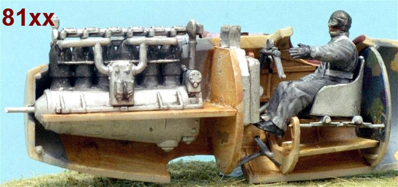
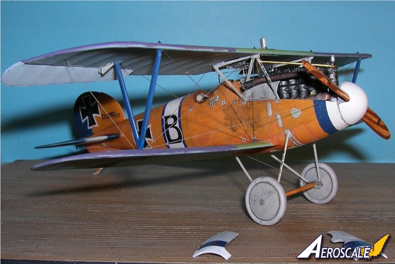
Now comes the build up of the generic Mercedes six cylinder inline engine (PP A 10
& 11, B 9, 30 & 32.) Erasing the center line seam and opening up the gaps between the
cylinders is needed. Depending on your adherence to the exact placement of the engine bearer shelf (PP B 4) in relation to the forward cockpit bulkhead (PP B 35) you can adjust the sit of your motor by removing the two lugs under the motor mount flanges on the sides. This lowers the front of the motor about 1/8 of an inch. Next, add R&R model detail nuts from Grandt Line to represent the motor mount nuts & bolts that would be apparent on the top face of the flanges. The upper portions of the cylinders are covered by water jackets and are the color of blued gun metal. The early D.V types saw the installation of the Mercedes D.IIIa 170hp. It has a small air pump in front of the #1 cylinder. The rocker assembly ( PP B 32) is representative of the 170hp. The immediate visual difference in the early Mercedes 160hp D.III / early 170hp D.IIIa and its progeny the late 170hp D.IIIa & all versions of the 180hp D.IIIaü is the rocker springs exposed above the cylinder jacket heads. On the early D.III and D.IIIa motors the rocker springs are centered on the sides of the rocker box covers. On the late 170hp and all of the D.IIIaü motor the springs are located on the forward leading edge of the same covers. The rest is below the cowling and not readily visible. The Mercedes 160hp was outclassed by 1917. The Mercedes D.IIIaü 180hp was the standard engine in both of the Albatros D.V & Va starting in late 1917 through 1918. Many, many D. III and IIIa type motors were rebuilt to the D.IIIaü specs at the airparks as the war progressed. That is why some captured examples had motors with the i.d. designation of 160hp D.III cast into their crankcases. This has caused the misconception that the standard 160hp and 170 hp were used in 1918 at a time when they had become obsolete.
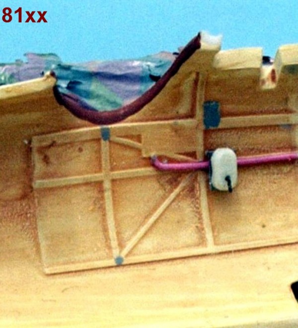
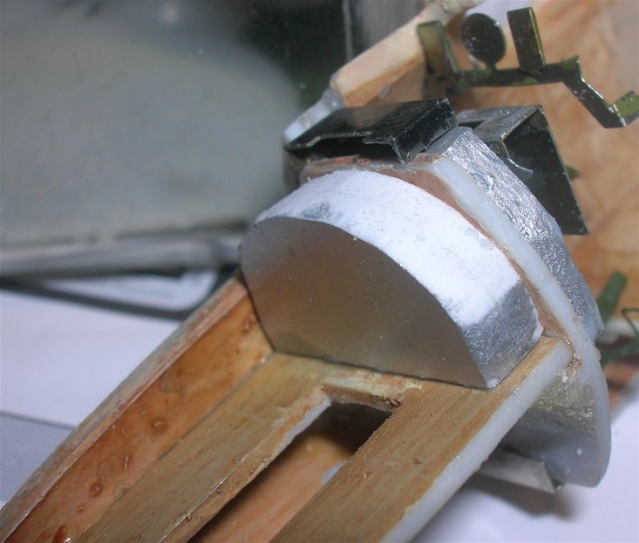
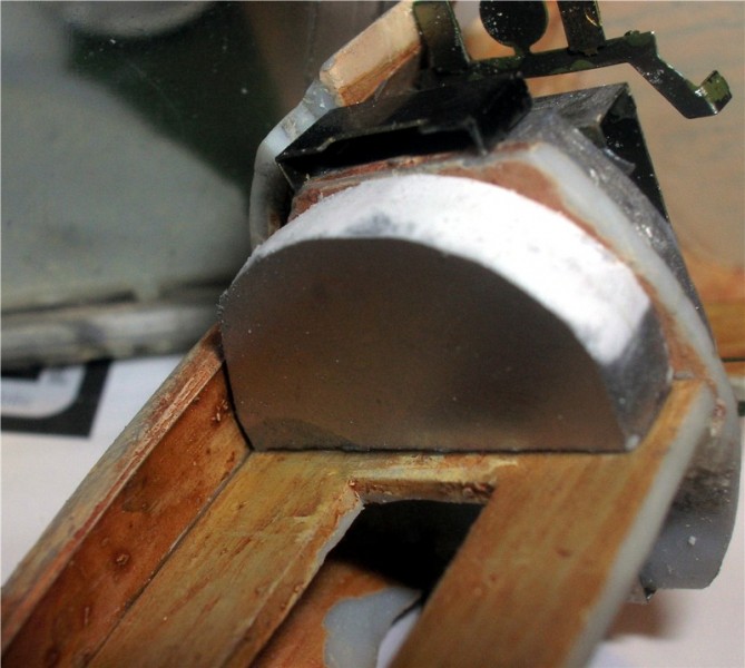
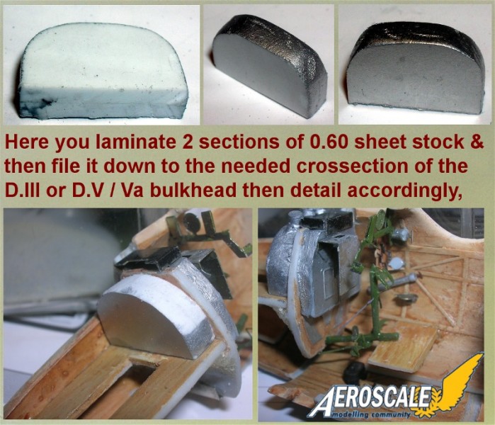
As mentioned if you are doing a mid to late production D.V or D.Va version you'll need to duplicate the Mercedes D.IIIaü180hp engine. Primarily the water pump on the late 170hp D.IIIa & all 180hp D.IIIaü is located directly behind the oil pump and some of the external plumbing is routed differently. Also it has a large stand up air pump in front of the #1 cylinder. Add fine wire painted black or white to make spark plug wires. Next I scratch build a reserve /main fuel tank assembly from a sandwich of 2 X .060 thou sheet plastic. These will rest behind the engine cylinders against forward cockpit bulkhead(PP B 35) & engine bearer shelf (PP B 4.). This tank should have two filler spouts and a fuel pump housing directly on top of the tank.
Concerning the twin Spandau Maxim machine guns The Albatros fighters used T shaped cocking handles in the cockpit leading from the cocking levers on the right side of the gun breeches and worked via a linkage system. By the way Eduard provided a couple of T shaped handles to represent the seat adjustment clamps (PE 34 X2.) Since these are not readily seen, they could be reassigned to machine gun duties. Otherwise build the guns as recommended. If you can get a set of 1/72 scale rear gun sights the are perfect for the 1/48 scale guns. Add a set of ^^ brackets to the forward facing edge of the forward cockpit bulkhead (PP B 35) to simulate forward gun supports. I also added the empty belt chutes with bent solder/flux . If you use the left chute cover (PP B 7) as seen on page 5 you'll only need one solder chute for the right gun.
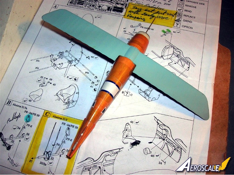
Page 5.) Pre-drill all strut and rigging locator holes. Join the fuselage halves (PP A 1 &2.) The only problem with that this new Eduard molding is the pilot's step located on PP A 1 is to far forward. It needs to be erased and then built up one bay further back. Careful sanding helps the horizontal tail unit (PP A 14) fit properly. I used gap filling super glue (semi gelatin) to fill joint seams between all plastic parts joined to the fuselage. I would usually add Eduard fittings to the fuselage at this point. It should be noted that on right fuselage half (PP A 2) the rear-most circular (right side) engine access panel needs to be erased in most cases. This panel is evident only in the last production series of the D.Va types. When adding the tail skid (PP B 8) try to see this piece under stress by adding a .020 shim behind the bungee chords touching the skid housings (PP A 5) and painting the shim and the chord area the same color.
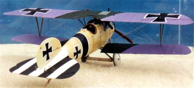
Page 6.) Check all the pre-drilled strut and rigging locator holes. Add the radiator shutter assembly (PE 10 & 11) after you have painted or applied lozenge decal to the under surface of the top wing. I generally paint the undersurface of the top wing and the upper surface of the lower wing at this point before assembly and rigging. The radiator faces are molded on the top wing (PP A 3.) Realistically though, with minor scraping & sanding one can use any of the alternatives available in the Toms Modelworks or Eduard aftermarket frets. It depends on which one is applicable to the machine you are building. I like to simulate the bands holding the auxiliary struts' (PP B 13 X2) with clear decal film. Also I replace the cabane struts (PP B 21 X 2) with cut and shape brass rod of an appropriate diameter. Otherwise all other kit parts I add as per instructions. Note also, the etched metal covers (PE 31 & 32 ) are for the Albatros D.Va variant not the D.V . These were the upper surface access covers for the aileron pulleys.
Page 7.) Don't add the windscreen film yet. The seam on the exhaust horn (PP A 12) can be erased and the open end drilled out partially to simulate the original. Next we see a prime example of a company listening to its customers. The one gripe that I have always heard from other modelers is that the original / early issue Eduard Albatros D.V /Va kits did NOT include the water pipes for the radiator intake and out flow. They are represented in the new mold as PP B 14 & 26.
The weakest part of a Veestrut landing gear assembly in plastic is the side to side twist. This causes the gear legs to break. I recommend replacing the landing gear legs (PP B 5 & 34) and the axle spreader bar (PP A 6) ends with the appropriate diameter bent and shaped rass rod. Try Aeroclub "STRUTZ". Check references for correct height of your scratchbuilt landing gear legs. I use upholstery thread to wrap around the lower legs of the landing gear with the axle in place to simulate the bungee shock chords. This looks like the original and actually secures the axle in place. Also a drop of Cynoacrylate here on the thread adds a great amount of strength. The kit rigging control horns (PE 29 X4 & 36 X 4) are mounted as recommended.
Eduard pulled another minor faux paux by molding the retainer stud or propeller hub (PP A 9 & 15) on the wrong face of the prop boss. I personally like scratchbuilding my kit propellers from light and dark woods. I have also learned to paint the laminations with convincing effect. Most Albatros fighters were equipped with the light and dark laminated propellers. Carefully check the aircraft profile your modeling to choose the right propeller. Don't limit your choices to the Eduard instructions. The D.V both used both types of propellers that have been offered with in the kit. The propeller parent company determined the paddle profile of the propeller (it was their trademark) while the engine application determined its pitch and length. So both profiles could be seen on either the D.V or the D.Va. But with different pitches because of the different horse power of the installed motor.
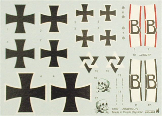
After final clear coating of your model attach your windscreen. Note I have included an image of the #8109 decal sheet to show previous variations.
Kit Decals for # 8112
A. Ltn. Monnington of Jasta 15 mid-1917.(seen in #8109.) In 1917, Kurt Monnington was transferred from FA62 to Jasta 15. With this unit, he gained no aerial victories.There was a transfer to Jasta 22s and then to the reformed Jasta 18. In March, 1918 he found himself with Jasta 18, in the so-called Berthold exchange, that saw the transfer of identities between Jasta 15 and Jasta 18. On May 11, he claimed his first kill (S.E.5a), and on June 5, his second (Bristol Fighter). After that, Jasta 18 was relocated from the northern sector of the front to the Montingen airfield at Metz. Here, Monnington gained five victories over British bombers in combat with the IndependentAir Force.
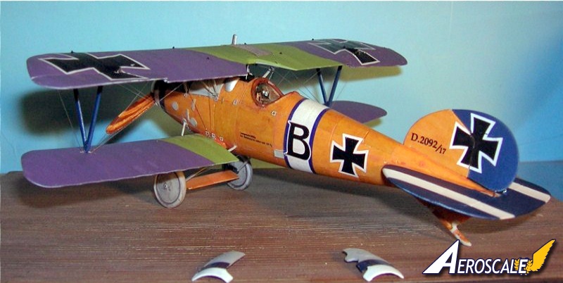
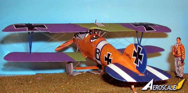
B. D.2092/17 in Jasta 79b livery, early 1918. (seen in #8109)By the time that Ltn. Walter Boning became the first CO of Jasta 76b, he had already six victories to his credit, achieved while attached to Jasta 19. With the new unit, he gained a further eleven kills over British and French aircraft. He gained the last two on May 30th, 1918, but the following day would prove fateful. On initiating combat with Camels from No.70 Squadron, RAF, he suffered a minor collision with a colleague, Vzfw. George Markert. Both were able to recover, but having lost focus, were immediately attacked. Markert went down in flames, while Boning was able to land at his own airfield, but did not recover from his injuries.
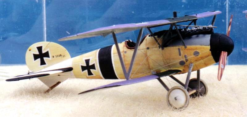
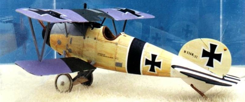
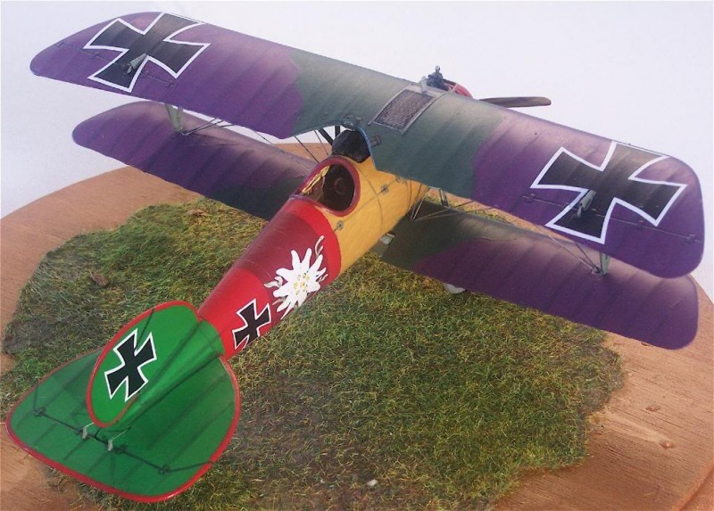
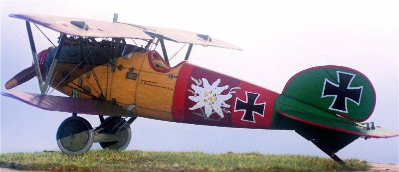
C. D.1148/17 in Jasta 6 livery as flown by Ltn. Hans Adam.The father of two, HansAdam was wounded as a soldier in September, 1914, and transferred to the air force in 1916, where he was attached to FF(A)2b. Here, he often flew with another future ace, Eduard von Schleich. In March, 1917,Adam was transferred to Jasta 34. Here, he gained three kills, before being transferred again, this time to Jasta 6. After the death of Eduard Dostler in August, 1917, he gained the function of Staffelfuhrer.On November 15, 1917, by then Ritter vonAdam, was shot down over Kortewild during combat with No.45 or No.65 Squadron Camels. By the time of his death, he shot down three French and 18 British aircraft.
D. Ltn. Wilhelm Lehmann of Jasta 5 in early 1918.Wilhelm Lehmann began his career in August, 1917 with Jasta 5. By September 6, he gained his first aerial victory. It wasnt until April, 1918, before he got his next. On May 12, he became CO of Jasta 5. Within a month, he got another two victories, but on June 26th, was himself shot down and killed, likely by the American Field E. Kindley. (Who's biography was first mentioned here on Aeroscale.)
E. Ltn. Alois Heldmann, Jasta 10, late 1917 Alois (Aloys by some references) Heldmann joined Jasta 10 in June, 1917 after usual service with Flieger Abteilungen. His first two, unconfirmed, kills came by May, and his first confirmed on June 22, 1917. His score continually grew so that by the end of the war, still with Jasta 10, he gained fifteen. As such, he became the third most successful pilot of the unit. Ahead of him were only Erich Lowenhardt with 54, and Friedrich Friedrichs with 21.
Express Masks
This kit has the Eduard Express Masks included. This is a system that employs gummed pre-cut paper. The purpose is for any modeler to get clean demarcations between different coloured paint applications. NEVER lay these down on, 'set' or 'dried on decals as they will rip or lift completely off when you remove the mask. I personally have used one set of the masks up to four times successfully.
Listed References
Albatros D.V/Va, War Horse of the Luftstreitkrafte by S.T. Lawson, SAM Pub. Model Aircraft Monthly, Vol 1 #2 , Pp.54-59.2002.
Albatros D.V/Va, Part II, The Spoils of War by S.T. Lawson.
Albatros Aces by Franks 2000, Osprey pub.#33.
Albatros Scouts Described by Chas Schaedel, 1971 Kookaburra Tech. Pub.
Albatros Fighters Datafile Special by Ray Rimell, 1991 Albatros Pub. Ltd.
Albatros D.V by Peter Gray, 1965 Profile Pub.#9.
Albatros D.V & D.Va Described and Drawn by Ian Stair,1972 Scale Models.
Albatros D.Va German Fighter of WWI by Robert Mikesh, Smithsonian Inst. Press.
Lafayette Foundation Archive. Denver CO. USA.
Scratchbuilding Techniques by Alan Clark, 1990 Scale Models Int. Pp174-5.
Scratchbuilt Albatros D.Va by Alan Clark,1990 Scale Models Int. Pp.491-495.
Spandau Machine Gun by David Watts,1998 WWI Aero.
'The Last Albatros' by Colin Owers 1988 Aviation News Pp.216-221.
* 'Neu' is German for the English word 'new' and was an unofficial nomenclature used in WWI German manufacturing in application to a 'next generation.' For instance the Seimens Halske Sh.III 160hp counter rotary was modified to specs taking it to 240hp. and called Sh.III neu
SUMMARY
Highs: Fine details and it has extras not found in any other manufacturer's kit.Lows: Landing gear legs about 3 mm too short and too thick. Instructions adding information about the D.Va when this kit is intended for the D.V. Pilot step needs to be relocated and prop hub molded on wrong side of prop face.Verdict: Solid good kit I have done about 17 of these Eduard Albatros D.V / Va kits. Even with a few minor problems this mold comes close to being the final word on the type at this scale.
Our Thanks to Eduard! This item was provided by them for the purpose of having it reviewed on this KitMaker Network site. If you would like your kit, book, or product reviewed, please contact us.
About Stephen T. Lawson (JackFlash) FROM: COLORADO, UNITED STATES
I was building Off topic jet age kits at the age of 7. I remember building my first WWI kit way back in 1964-5 at the age of 8-9. Hundreds of 1/72 scale Revell and Airfix kits later my eyes started to change and I wanted to do more detail. With the advent of DML / Dragon and Eduard I sold off my ...
Just bringing this up for a fellow modeler who wanted clarification.
Checking images carefully you can see the leading edge of the prop should be curved in this example. (To be fair it was his first attempt. And he did not know about our site.) He does seem to be on top of the rigging. Also the water tower to the radiator appears missing.
Note how the spinner and the prop base don't match up as it should.


Comments